1
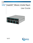
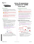
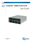
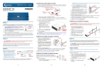
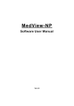
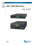
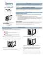
Overview
Tape drives are mounted inside individual drive shoe assemblies at the rear of the library. This allows the
flexibility to remove or replace a tape drive while the other tape drives and library robotics remain active. The
SCSI connectors for the tape drives are part of a separate module and remain in the library when the tape drive
is removed.
Inspect Shipping Container
Add-On Instruction
Visually inspect the shipping containers and notify your carrier immediately of any damage. Place shipping
container on a clean surface and carefully remove and verify the contents against the packing list. If parts are
missing or the equipment is damaged, notify your representative. Always save the containers and packing
materials for any future reshipment.
Safety Notes
Drive Shoe Assembly
Electrostatic Discharge Information
A discharge of static electricity can damage static-sensitive devices or micro-circuitry. Proper packaging and
grounding techniques are necessary precautions to prevent damage. To prevent electrostatic damage, observe
the following precautions:
•
•
•
•
•
•
•
GETTING HELP!
Transport products in static-safe containers such as conductive tubes, bags, or boxes.
Keep electrostatic-sensitive parts in their containers until they arrive at static-free stations.
Cover the library with approved static-dissipating material. Provide a wrist strap connected to the work surface
and properly grounded tools and equipment.
Keep the work area free of non-conductive materials, such as ordinary plastic assembly aids and foam packing.
Make sure you are always properly grounded when touching a static-sensitive component or assembly.
Avoid touching pins, leads, or circuitry.
Use conductive field service tools.
Cautions and Notes
System power in the library does not completely shut off using the Graphical User Interface (GUI) touch screen.
You must turn off library power using the circuit breakers on the power strip and disconnect the AC power cord
from the the power strip to completely remove all power from the library.
You can get support via the Internet at
www.overlandstorage.com, or call Tech Support at
800 729-8725 Option 5
To reduce the risk of electric shock or damage to the equipment, disconnect power from the library by
unplugging the power cords from either the electrical outlet or the power strip.
©2004 Overland Storage, Inc.
(JUN 2004)
Part Number 104339-101
Adding a Drive
Adding a Drive Shoe Assembly
This instruction explains how to add a tape drive to a NEO 8000 library. See your
reseller or visit Overland’s website for a list of tape drives supported by this
library
CAUTION
With a blank panel or tape drive removed, there is access to
moving parts. DO NOT reach into open cavities
VORSICHT
Wenn eine Gehäuseplatte oder ein Band-Laufwerk entfernt
wurde, gibt dies Zugang zu sich bewegenden Teilen. Greifen
Sie NICHT in den Hohlraum.
NOTE: Drives must be installed in sequence following the numbering
NEO-8049k
4.
adjacent to the drive bay opening.
1.
Push the Drive Shoe Assembly slowly into the receiver until it seats
against the back of the library.
Remove the upper and lower retaining screws that secure the blank panel
cover plate to the drive opening where you plan to install the new drive .
NEO-8049m
5.
Tighten the two captive retainer screws to secure the module to the
library.
6.
If the removal and replacement was done with the library operational
and the Auto Power-up An Installed Drive After Timeout feature
from the Library Options page is disabled, reactivate the drive by
selecting Menu > Maintenance > Replace Drive > Reactivate
Drive n.
NEO-8049j
2.
Keep the panel cover plate for future use.
3.
Fully support the Drive Shoe Assembly while starting it into the receiver
being careful not to damage the tape drive or connectors.
NOTE: LED on the rear of the drive should be green when initialized.
7.
If the power was off during the procedure, power on the library. The
drive will be reactivated during the power on initialization of the library.
8.
Refer to NEO 8000 User manual for cabling configuration examples.
Setting a SCSI ID For Native SCSI Drives
Setting a SCSI ID
Each SCSI configured tape drive installed in the library requires a unique SCSI ID. The information provided in this section instructs you on how to set a
SCSI ID.
To set a SCSI ID:
1) With the Default screen displayed, Figure 1, select the Menu option from the Default screen, see Figure 2.
2) Enter the appropriate password if required. See the section on “Front Panel and Media Locks” in the NEO 8000 User manual on how to set
passwords.
3) Select SCSI/FC in the Edit Options area to display the following screen, see Figure 3.
.
Figure 1
Figure 2
Figure 3
NOTE: You can move to the next sequential SCSI options screen by selecting the T. To return to the previous SCSI options screen select the S . The Back button
to return you to the Menu screen.
4) For example, to set the Drive 1 Bus ID to 3:
a.Select the box next to the text “Drive 1 Bus ID, The Drive 1 Bus ID screen appears on the display, see Figure 4. This screen displays the current
Drive 1 Bus ID along with the new value that you request.
b.Touch the block that contains the number 3. This places your request into the New data field.
c.Touch the Save option to confirm your request. A confirmation screen appears on the display, see Figure 5.
d.Select OK to confirm. The newly selected SCSI ID flashes for a few seconds while the drive is being updated, then remains solid indicating that
the operation is complete, see Figure .6. Press the Back button repeatedly to return to the Main menu screen.
.
Figure 5
Figure 4
Figure 6
5) Repeat this procedure for each SCSI drive added.
Native Fibre Channel Drive Configuration Set Values
NOTE: The NEO SERIES 8000 library requires a minimum library firmware level of 2.01 to correctly operate with native fibre channel drives installed. Verify the
firmware level of your library by selecting Menu/Library Info buttons from the default screen. If the library does not meet the minimum firmware level
requirements, you can obtain the proper firmware level by selecting the SERVICE & SUPPORT at Overland Storage’s website ( www.overlandstorage.com).
In most cases you can use the default configuration values for the native fibre channel drives. Changeable fibre channel drive configuration values are:
Port n Control, Port n Loop Id, World Wide Port n Name, World Wide Node Name, Topology, Speed and Directory Registration. Refer to the
NEO 8000 User manual for a more detailed description on configuring these options.
To view the fibre channel drive configuration:
1 With the Default screen displayed (Figure 7), select the Menu option from the default screen, see Figure 8.
2) Enter the appropriate password if required. See the section on “Front Panel and Media Locks” in the NEO 8000 User manual on how to set
passwords.
3) Select SCSI/FC in the Edit Options area to display the Drive Configuration screen, see Figure 9.
.
Figure 7
Figure 8
Figure 9
4) Select the “Set Values” button located ajacent to the Drive n Configuration to access the edit configuration values, Figure 10 and Figure 11.
Figure10
Figure 11
NOTE: You can move to the next sequential Drive Configuration screen screen by selecting the T, see Figure 10. To return to the previous Drive
Configuration screen select the S , see Figure 11. Select the Back button to return you to the Menu screen.