1
GSK 218M CNC System
Connection and PLC Manual
GSK218M CNC System
Connection and PLC Manual
The user manual describes all items concerning the operation
of this CNC system in detail as much as possible. However, it’s
impractical to give particular descriptions for all unnecessary and/or
unavailable operations on the motor due to the limit of the manual,
specific operations of the product and other causes. Therefore, the
operations not specified in this manual may be considered impossible
or unallowable.
This manual is the property of GSK CNC Equipment Co., Ltd. All
rights reserved. It is against the law for any organization or individual to
publish or reprint this manual without the express written permission of
GSK CNC Equipment Co., Ltd. and the latter reserves the right to
ascertain their legal liability.
1
GSK218M CNC System
Connection and PLC Manual
Company profile
GSK——GSK CNC Equipment Co,. Ltd is the largest production and marketing
enterprise of the CNC system in China currently. It is the Numerical Control industrial base
of South China, and the undertaking enterprise of the 863 national main project
Industrialization Support Technology for Medium Numerical Control System as well as one
of the 20 basic equipment manufacture enterprises in Guangdong province. It has been
taking up the research and development, design and the manufacture of machine CNC
system (CNC device, drive unit and servo motor) in recent 10 years. Now it has developed
into a large high-tech enterprise integrated with research, education, industry and trade by
enhancing the popularization and trade of CNC machine tools. There are more than 1400
staffs in this company that involves 4 doctors, more than 50 graduate students and 500
engineers and more than 50 among them are qualified with senior technical post titles. The
high performance-cost ratio products of GSK are popularized in China and Southeast Asia.
And the market occupation of GSK’s product dominates first and the turnout and sale ranks
the top in internal industry for successive 7 years from the year 2000 to 2006, which makes
it the largest CNC manufacture base throughout China.
The main products provided by our company includes the NC equipments and devices
such as GSK series turning machine, milling machine, machining center CNC system, DA98,
DA98A, DA98B, DA98D series full digital stepper motor drive device, DY3 series compound
stepper driver device, DF3 series response stepper motor driver device, GSK SJT series AC
servo motors, CT-L NC slider and so on. The current national standard (and international
standard), industry standard, as well as the enterprise standard (or enterprise internal
standard) as a supplementary, are completely implemented in our production process. The
capability of abundant technology development and complete production and quality
system qualified by us will undoubtedly ensure the reliable product to serve our customers.
24~48 hours technological support and service can be easily and promptly provided by our
complete service mechanism and tens of service offices distributed in provinces around
China and abroad. The pursuit of “excellent product and superexcellent service” has made
the GSK what it is now, and we will spare no efforts to continue to consummate this South
China NC industry base and enhance our national NC industry by our managerial concept
of “century enterprise, golden brand”.
2
GSK218M CNC System
Connection and PLC Manual
Technological Spot Service
You can ask for spot service if you have the problems that can’t be solved by telephone. We
will send the engineers authorized to your place to resolve the technological problems for
you.
Foreword
Dear user,
It’s our pleasure for your patronage and purchase of this GSK GSK218M CNC system made
by GSK CNC Equipment Co., Ltd.
The manual is “Connection and PLC Manual”.
!
Accident may occur by improper connection and operation!This
system can only be operated by authorized and qualified personnel.
Please carefully read this manual before usage!
This manual is reserved by final user.
All specifications and designs herein are subject to change without further notice.
We are full of heartfelt gratitude to you for supporting us in the use of GSK’s products.
3
GSK218M CNC System
Connection and PLC Manual
Warning and precautions
Warning, notice and explanation
This manual contains the precautions to protect user and machine. The precautions are classified
as warning and notice by safety, and supplementary information is regarded as explanation. Read
the warnings, notes and explanations carefully before operation.
Warning
User may be hurt or equipment can be damaged if operations and steps are not observed.
Notice
Equipment may be damaged if operation instructions or steps are not observed by user.
Explanation
It is used for the supplementary information except for warning and notice.
z
Copy right is reserved.
4
GSK218M CNC System
Connection and PLC Manual
Contents
Ⅰ
PROGRAMMING ................................................................................................. 1
1 Sequence Program Creating Process ...................................................................................................................... 2
1.1 GSK218M PLC specification ..................................................................................................................... 2
1.2 What is a sequence program .................................................................................................................... 2
1.3 Establishment of interface specifications(step 1).............................................................................. 2
1.4 Establishment of ladder diagram(step 2)............................................................................................ 2
1.5 Sequence program check(step 3) ....................................................................................................... 3
2 Sequence Program.................................................................................................................................................... 4
2.1 Execution process of sequence program ................................................................................................ 4
2.2 Repetitive cycle ........................................................................................................................................... 5
2.3 Priority of execution(1st level, and 2nd level)............................................................................................ 5
2.4 Sequence program structure..................................................................................................................... 6
2.5 Processing I/O (input/output) signals ....................................................................................................... 7
2.5.1 Input signal processing .....................................................................................................8
2.5.2 Output signal processing...................................................................................................8
2.5.3 Synchronous processing short pulse signal ......................................................................8
2.5.4 Difference state of signals between 1st level and 2nd level ................................................9
2.6 Interlocking................................................................................................................................................... 10
3 Address .................................................................................................................................................................... 11
3.1 Addresses from Machine tool to PLC(X)............................................................................................ 11
3.1.1 Assignment of IO module X address............................................................................... 11
3.1.2 Assignment of MDI panel X address ............................................................................... 11
3.2 Address (Y) from PLC to machine tool .................................................................................................... 13
3.2.1 Assignment of IO module Y address ..............................................................................13
3.2.2 Assignment of IO module Y address ...............................................................................13
3.3 Address (G) from PLC to CNC................................................................................................................ 15
3.4 Address (F) from CNC to PLC ................................................................................................................ 16
3.5 Internal relay address(R) .................................................................................................................... 16
3.6 Address of keep relay(K) .................................................................................................................... 17
3.7 Addresses(A) for message selection displayed on CRT..................................................................... 17
3.8 Address of meter(C) ............................................................................................................................ 18
3.9 Meter preset address(DC) ....................................................................................................................... 18
3.10 Timer addresses(T) ............................................................................................................................. 18
3.11 Addresses of timer preset value(DT) ................................................................................................ 18
3.12 Address of data table(D)..................................................................................................................... 18
3.13 Label address(L).................................................................................................................................. 19
3.14 Subprogram numbers(P).................................................................................................................... 19
4
PLC Basic Instruction......................................................................................................................................... 20
4.1 RD, RD.NOT, WRT, WRT.NOT ................................................................................................................. 20
4.2 AND, AND.NOT instructions...................................................................................................................... 21
4.3 OR, OR.NOT instructions .......................................................................................................................... 21
4.4 OR. STK instruction .................................................................................................................................... 22
4.5 AND.STK instruction................................................................................................................................... 22
5 PLC Functional Instructions ................................................................................................................................. 24
5.1 END1(1st level sequence program end) ........................................................................................... 25
5.2 END2(2nd level sequence program end) .......................................................................................... 25
5.3 CALL(call subprogram) ....................................................................................................................... 25
5.4 SP(Subprogram) .................................................................................................................................. 26
5.5 SPE(subprogram end) ........................................................................................................................ 26
5.6 SET(set) ................................................................................................................................................ 27
5
GSK218M CNC System
5.7
5.8
5.9
5.10
5.11
5.12
5.13
5.14
5.15
5.16
5.17
5.18
5.19
5.20
5.21
5.22
5.23
5.24
5.25
5.26
5.27
5.28
5.29
5.30
Connection and PLC Manual
RST(reset) ............................................................................................................................................ 27
JMPB(label jump)................................................................................................................................. 27
LBL(Label) ............................................................................................................................................ 28
TMR(timer)............................................................................................................................................ 29
CTR(binary counter) ............................................................................................................................ 29
DEC(binary decode)............................................................................................................................ 30
COD(binary code conversion) ........................................................................................................... 31
COM (common line control) .................................................................................................................... 33
COME (common line control end) .......................................................................................................... 33
ROT(Binary rotation control) .............................................................................................................. 34
SFT(shift register) ................................................................................................................................ 36
DIFU(rising edge check)..................................................................................................................... 37
DIFD(falling edge check) .................................................................................................................... 37
COMP(binary comparison)................................................................................................................. 38
COIN(coincidence check)................................................................................................................... 39
MOVN(transfer of data) ...................................................................................................................... 39
XMOV(Binary index data transfer) .................................................................................................... 40
DSCH (binary data search) ............................................................................................................... 42
ADD(addition)....................................................................................................................................... 43
SUB(binary subtraction) ..................................................................................................................... 44
ANDF(functional and) ......................................................................................................................... 45
ORF(functional or) ............................................................................................................................... 46
NOT(logical not)................................................................................................................................... 47
EOR(exclusive or) ............................................................................................................................... 48
6 Ladder Writing Limit............................................................................................................................................. 49
Ⅱ
FUNCTION........................................................................................................... 50
1 Controlled Axis ....................................................................................................................................................... 51
1.1 Outputting of movement state of an axis ............................................................................................... 51
1.2 Servo ready signal .................................................................................................................................... 52
2 Preparation for Operation..................................................................................................................................... 53
2.1 Emergency stop ........................................................................................................................................ 53
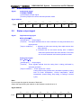
2.2 CNC overtravel signal............................................................................................................................... 53
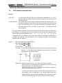
2.3 Alarm signal ............................................................................................................................................... 54
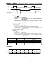
2.4 Mode selection .......................................................................................................................................... 55
2.5 Status output signal................................................................................................................................... 55
3 Manual Operation .................................................................................................................................................. 56
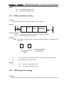
3.1 JOG feed/incremental feed...................................................................................................................... 56
3.2 MPG/Step feed .......................................................................................................................................... 57
4 Reference Point Return.......................................................................................................................................... 58
4.1 Manual reference point return ................................................................................................................. 58
4.2
Reference point return check signal ...................................................................................................... 59
4.3 Area check signal...................................................................................................................................... 60
5 Automatic Operation.............................................................................................................................................. 63
5.1 Cycle start/feed hold ................................................................................................................................. 63
5.2 Reset........................................................................................................................................................... 66
5.3 Testing a program ..................................................................................................................................... 66
5.3.1
Machine tool lock...........................................................................................................66
5.3.2
Dry run ..........................................................................................................................67
5.3.3
Single block ...................................................................................................................68
5.4 Optional block skip.................................................................................................................................... 68
5.5 Program restart.......................................................................................................................................... 69
6
GSK218M CNC System
Connection and PLC Manual
6 Feedrate Control..................................................................................................................................................... 71
6.1 Rapid traverse rate ................................................................................................................................... 71
6.2 Feedrate override...................................................................................................................................... 71
6.3 Override cancel ......................................................................................................................................... 72
7 Auxiliary Function ................................................................................................................................................. 73
7.1 Miscellaneous function (M code) ...................................................................................................... 73
7.4 Auxiliary function lock ............................................................................................................................... 77
8
Spindle Speed Function....................................................................................................................................... 79
8.1 Spindle speed control mode .................................................................................................................... 79
8.1.1 Gear spindle....................................................................................................................79
8.1.2 Analog spindle ................................................................................................................79
8.2 Rigid tapping .............................................................................................................................................. 81
9
Programmng Instruciton .................................................................................................................................... 82
9.1 Custom macro program ........................................................................................................................... 82
9.2 Canned cycle ............................................................................................................................................. 84
10 Display/Set............................................................................................................................................................. 86
10.1 Clock Function......................................................................................................................................... 86
10.2 Displaying operation history .................................................................................................................. 86
10.3 Help function............................................................................................................................................ 86
11 Measurement ........................................................................................................................................................ 87
11.1 Skip function .............................................................................................................................................. 87
12 Panel locked setting .............................................................................................................................................. 88
Appendix .................................................................................................................................................................... 89
Signal list (During order of address) .................................................................................................................. 89
Ⅲ
OPERATION .......................................................................................................... 93
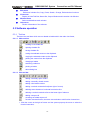
1 PLC Window Display............................................................................................................................................. 94
1.1 Automatic operation when GSK218M PLC power on.......................................................................... 94
1.2 INFO window display................................................................................................................................ 94
1.2.1
INFO window.................................................................................................................94
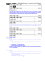
1.2.2
PLCGRA window...........................................................................................................96
1.2.3
PLCPAR window ...........................................................................................................96
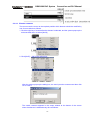
1.2.4
PLCGND window ..........................................................................................................97
1.2.5
PLCTRA window ...........................................................................................................98
2 PLC Programming Operation............................................................................................................................. 100
2.1 General ..................................................................................................................................................... 100
2.2 Basic instruction(B. INST)...................................................................................................................... 101
2.3 Operations of ladder ............................................................................................................................... 102
2.4 Function instruction................................................................................................................................. 104
2.5 Instruction list........................................................................................................................................... 104
2.6 Edit instruction ......................................................................................................................................... 106
2.7 PLC operation step ................................................................................................................................. 106
3 PLC Address, Parameter Setting ........................................................................................................................ 108
3.1 Counter ..................................................................................................................................................... 108
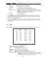
3.2 Timer ......................................................................................................................................................... 109
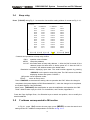
3.3 Data list..................................................................................................................................................... 110
3.4 Keep relay ................................................................................................................................................ 111
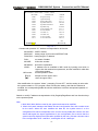
3.5 F address corresponded to M function ................................................................................................ 111
4
PLC address check operation ........................................................................................................................... 113
7
GSK218M CNC System
Connection and PLC Manual
5 Ladder edit software use...................................................................................................................................... 114
5.1 Summary ....................................................................................................................................................... 114
5.2 Software introduction................................................................................................................................... 114
5.2.1 Starting software ........................................................................................................... 114
5.2.2 Function introduction..................................................................................................... 114
5.3 Software operation....................................................................................................................................... 115
5.3.1 Tool bar ......................................................................................................................... 115
5.3.2 Selecting a graph .......................................................................................................... 116
5.3.3 Editing a graph .............................................................................................................. 117
5.3.4 Ladder comment ........................................................................................................... 118
Ⅳ
CONNECTION ..................................................................................................... 121
1 System Structure and Installation....................................................................................................................... 122
1.1 System composition .................................................................................................................................... 122
1.2 System installation & connection............................................................................................................... 122
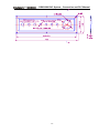
1.3 CNC system installation dimension........................................................................................................... 123
2 Device Connection ................................................................................................................................................ 127
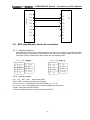
2.1 CNC external connection............................................................................................................................ 127
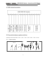
2.2 Connection between system and driver ................................................................................................... 127
2.2.1 System interface ...........................................................................................................127
2.2.2 Interface signal list ........................................................................................................128
2.2.3 Signal specification .......................................................................................................128
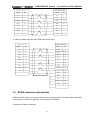
2.2.4 Cable connection ..........................................................................................................130
2.3 RS232 standard serial interface.............................................................................................................. 131
2.4 MPG (handwheel), hand unit connection .............................................................................................. 132
2.4.1 Interface signal list ........................................................................................................132
2.4.2 Interface signal..............................................................................................................132
2.5 Spindle unit connection ............................................................................................................................... 134
2.5.1 Interface signal list ........................................................................................................134
2.5.2 Interface signal..............................................................................................................134
2.6 Power supply interface................................................................................................................................ 134
3 Machine Control I/O Interface............................................................................................................................ 135
3.1 Interface signal list ....................................................................................................................................... 135
3.2 Input interface............................................................................................................................................... 135
3.2.1 Input interface method ..................................................................................................135
3.2.2 Input signal interface definition......................................................................................136
3.3 Output signal................................................................................................................................................. 138
3.3.1 Output interface method................................................................................................138
3.3.2 Output signal interface definition ...................................................................................138
4 Debugging Machine.............................................................................................................................................. 140
4.1 Debug preparation ....................................................................................................................................... 140
4.2 System power on ......................................................................................................................................... 140
4.3 Emergency stop and limit ........................................................................................................................... 141
4.4 Gear ratio adjustment.................................................................................................................................. 142
4.5 Backlash compensation .............................................................................................................................. 142
4.6 Parameter of servo ...................................................................................................................................... 143
4.7 Machine pitch compensation...................................................................................................................... 144
4.8 Machine zero return..................................................................................................................................... 146
4.9 Input/output signal control of spindle CW/CCW ...................................................................................... 147
4.10 Spindle automatic gear change control .................................................................................................. 148
4.11 External cycle start and feed hold ........................................................................................................... 149
4.12 Cooling, lubricant and chip removal control........................................................................................... 150
4.13 Parameters of axis control........................................................................................................................ 151
4.14 Parameter of coordinate system.............................................................................................................. 152
4.15 Parameter of feedrate ............................................................................................................................... 152
4.16 Parameters of MDI, display and edit....................................................................................................... 154
8
GSK218M CNC System
Connection and PLC Manual
4.17 Parameters of tool compensation............................................................................................................ 156
Appendix: .............................................................................................................................................................. 158
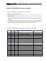
Guide for GSK218M matching with ladder ..................................................................................................... 158
1. Notices of GSK218M matching with turret tool magazine.....................................................158
2. Allocation and definition of PLC IO address, auxiliary relay and register ..............................158
3. Usage and maintenance of GSK 218M CNC System matching with turret tool magazine ...177
4. Macro program statement of GSK218M CNC System matching with turret tool magazine ..180
9
GSK218M CNC System
Ⅰ
Connection and PLC Manual
Programming
1
GSK218M CNC System
Connection and PLC Manual
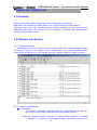
1 Sequence Program Creating Process
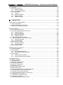
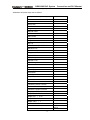
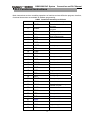
1.1
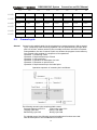
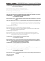
GSK218M PLC specification
Specifications of GSK218M PLC are as follows:
Specification
Programming method language
Number of ladder level
1st level execution period
Mean processing time of basic instruction
Program capacity
Instruction
GSK218M
Ladder
2
8ms
10μs
4700 step
Basic
instruction
instruction
0~511 byte
0~31 byte
Internal relay
(R)
PLC message request (A)
Keep memory
* Timer
(T)
* Meter
(C)
* Data table (D)
* Keep relay (K)
* Meter preset value data register (DC)
* Timer preset value data register (DT)
Subprogram
(P)
Label
(L)
I/O module(X)
(Y)
1.2
PLC
+function
0~127 byte
0~127 byte
0~255 byte
0~63 byte
0~127 byte
0~127 byte
0~99
0~99
0~63
0~47
byte
byte
What is a sequence program
A sequence program is a program for sequence control of machine tools and other systems.
The program is converted into a format to enable CPU execute encoding and arithmetic
processing, and stored into RAM. CPU reads out instructions of the program stored into the
memory at the high-speed every instruction and execute the program by arithmetic operation
The sequence program is written firstly from ladder.
1.3
。
Establishment of interface specifications(step 1)
After deciding the control object specification, calculate the number of input/output signal points,
create the interface specification.
For input/output interface signals, see Chapter 4.
1.4
Establishment of ladder diagram(step 2)
Express the control operations decided by 218M ladder diagram. For the timer, meter, etc, which
2
GSK218M CNC System
Connection and PLC Manual
cannot be expressed with the functional instructions.
The edited ladder should be converted into the corresponding PLC instruction to store.
1.5
Sequence program check(step 3)
The sequence program can be checked in two ways:
1) Check by simulator
Instead of the machine, connect a simulator (consisting of lamps and switches). Switch
ON/OFF stands for the input signal state of machine, lamp ON/OFF for the output signal
state.
2) Actual operation debugging
Debug sequence program through operating the machine. Do measures against the
unexpected affairs before debugging.
3
GSK218M CNC System
Connection and PLC Manual
2 Sequence Program
Since PLC sequence control handled by software and operates on principle difference from a
general relay circuit, the sequence control method must be fully understood in order to design PLC
sequence program.
2.1
Execution process of sequence program
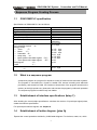
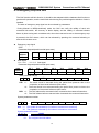
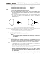
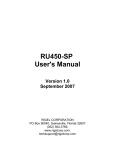
In general relay control circuit, each relay operates at approximately the same time, in the figure
below for example, when relay A operate, the relay D and E operate at approximately the same
time(when contacts B and C are off)., In PLC sequence control, each relay of circuit operates
sequentially. When relay A operates, relay D operates, then relay E(see the below figure). Thus
each relay operates in sequence which can be written as a ladder diagram. (programmed
sequence).
A
B
D
A
C
E
Fig. 2.1(a) circuit example
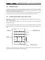
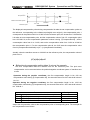
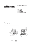
Fig.(b) and (c) illustrate operations varying from the relay circuit to PLC program.
A
C
B
A
C
Fig. 2.1(b)
A
C
A
C
B
Fig. 2.1(c)
(1) Relay circuit
In Fig. (A) and (B), the operations are the same. Turning on A turns on B and C. Turning on C
turns off B.
(2) 218M PLC program
In Fig.(B), as in the relay circuit, turning on A turns on B and C, and after one cycle of the PLC
4
GSK218M CNC System
Connection and PLC Manual
sequence, turns off B. But in Fig.(C), turning on A turns on C, but does not turn on B.
2.2
Repetitive cycle
The sequence program is executed from the beginning of coding to the end of coding of the ladder
diagram in the sequence written. When the sequence program ends, the program starts over form
the beginning. This is called repetitive operation.
The execution time from the beginning to the end of the ladder diagram is called the sequence
processing time. The shorter the process time is, the better the signal response becomes.
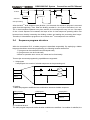
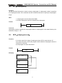
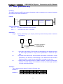
2.3
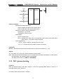
Priority of execution(1st level, and 2nd level)
GSK218M PLC consists of two parts: 1st level sequence part, 2nd level sequence part. They have
different execution period.
The 1st level sequence part operates every 4ms, which can operate the short pulse signal with
high-speed response).
The 2nd level sequence part operates every 4*n ms. Here n is a dividing number for the 2nd level
sequence part. The 2nd level sequence part is divided into n part, and every part is executed every
4ms.
1st level
sequence part
END1
Specifies the end of the
1st level sequence part
Division 1
Division 2
2nd level
sequence program
END2
Division n
Specifies the end of the
nd
2 level sequence part
218M PLC is solely executed in PLC-AVR single unit, and the second 2ms of every 4ms is the
communication time of CNC reading or writing PLC data.
5
GSK218M CNC System
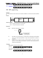
4
1
1st level
Connection and PLC Manual
4
4
1
1
7
Division 1
Division 2
Division n
2nd level
CNC processing
After the last 2nd level sequence part (division n) is executed, the sequence program is executed
again from the beginning. Thus, when the dividing number is n, the cycle of execution is 4*n ms.
The 1st level sequence operates every 4ms, and the 2nd level sequence every 4*n ms. If the steps
of the 1st level sequence is increased, the steps of the 2nd level sequence operating within 4ms
becomes less, thereby increasing the dividing number and making the processing time longer.
Therefore, it is desirable to program so as to reduce the 1st level sequence to a minimum.
2.4
Sequence program structure
With the conventional PLC, a ladder program is described sequentially. By employing a ladder
language that allows structured programming, the following benefits are derived:
1. A program can be understood and developed easily
2. A program error can be found easily.
3.When an operation error occurs, the cause can be found easily.
Three major structured programming capabilities are supported:
1) Subprogram
A subprogram can consist of a ladder sequence as the processing unit.
A
C
B
Job A
A
C
Job B
2) Nesting
Ladder subprograms established are combined to structure a ladder sequence.
Main program
Job A
Subprogram 1
Subprogram 2
Job A1
Job A11
Job A12
Job B
Job An
3) Conditional branch
The main program loops and checks whether conditions are satisfied. If a condition is satisfied, the
6
GSK218M CNC System
Connection and PLC Manual
corresponding subprogram is executed. If the condition is not satisfied, the subprogram is skipped.
Main program
Subprogram 1
Process 11
Process 1
State 1
Process 12
State 2
Process 2
Process 13
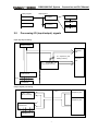
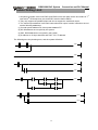
2.5
Processing I/O (input/output) signals
Input signal processing:
CNC
CNC—PLC
Share memory
PLC
1st
level
sequence
part
2nd sequence part
starting memory
2nd
level
sequence
part
2nd sequence part
input signal memory
Input signals from
machine tool
4ms
IO interface
Output signal processing:
CNC
PLC
CNC—PLC
Share memory
1st
level
sequence part
2nd
level
sequence part
output memory from
machine tool
4ms
IO interface
7
2.5.1
GSK218M CNC System
Input signal processing
Connection and PLC Manual
(1)Input memory of NC
The input signals from NC are loaded in memory of NC and are transferred to the PLC at intervals
of 4ms. Since the 1st level sequence part directly refer to these signal and process operations.
(2)Input signal memory to machine tool
The input signal memory stores signals transferred from the machine tool at intervals of 2ms
period. Since the 1st level sequence part directly refer to these signal and process operations.
(3)2nd level input signal memory
The 2nd level input signal memory is also called as 2nd level synchronous input signal memory. The
stored signals are processed by the 2nd level sequence part. State of the signals set this memory
synchronizes with that of 2nd level sequence part.
Input memory Signals from NC and machine tool are transferred to the 2nd level input signal
memory only at the beginning of execution of the 2nd level sequence part. Therefore, the state of
the 2nd level synchronous input signal memory does not change from the beginning to end of the
execution of the 2nd level sequence part.
2.5.2
Output signal processing
(1)NC output memory
The output signals are transferred form the PLC to the NC output memory at intervals of 4ms.
(2)Output signals to machine tool
Output signal to the machine tool from PLC output signal memory to the machine tool.
Note:
The state of the NC input memory, NC output memory, input signals from machine, input/output
memory signals to machine can be checked by using the PC self-diagnosis function. The
self-diagnosis number specified is the address number used by the sequence program.
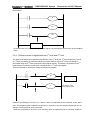
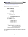
2.5.3
st
Synchronous processing short pulse signal
1 level sequence part is used for processing the short pulse signal. But when it is less than 4ms,
namely, when 1st level sequence is executed, the state of input signal may change as follows:
A
B1
A
B2
END1
8
GSK218M CNC System
Connection and PLC Manual
When A=0, and B1=1, A becomes 1, at this time, the next line of ladder is executed, B2=1. B1 and
B2 are also 1
R
B1
B2
END1
B1 and B2 are not 1 simultaneously after the signal A is processed synchronously by the medium
relay.
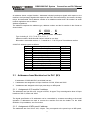
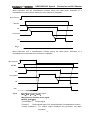
2.5.4 Difference state of signals between 1st level and 2nd level
The state of the same input signal may be different in the 1st level and 2nd level sequences. That is,
at 1st level, processing is performed using input signal memory and at 2nd level, processing is
performed using the 2nd level synchronous input signal memory. Therefore, it is possible for a 2nd
level sequence execution at the worst, compared with a 1st level input signal.
This must be kept in mind when writing the sequence program.
A
B
END1
A
C
2st division of 2st
level sequence part
When the processing is 1st 4ms, A=1, and B=1 after 1st sequence part is executed. At the same
time, 2nd sequence part is started to execute A=1 is stored to the 2nd sequence part and the 1st
division of 2nd sequence part is executed.
When the processing is 2nd 4ms, A=0, and B=0 after 1st sequence part is executed. And then
9
GSK218M CNC System
Connection and PLC Manual
2nd division of 2nd sequence part is executed, at this time, A is still 1. So C=1.
So, B and C are different.
2.6
Interlocking
Interlocking is externally important in sequence control safety.
Interlocking with the sequence program is necessary. However, interlocking with the end of the
electric circuit in the machine tool magnetic cabinet must not be forgotten. Even though logically
interlocked with the sequence program (software), the interlock will not work when trouble occurs
in the hardware used to execute the sequence program. Therefore, always provide an interlock
inside the machine tool magnetic cabinet panel to ensure operator safety and to protect the
machine from damage.
10
GSK218M CNC System
Connection and PLC Manual
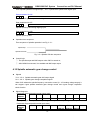
3 Address
An address shows a signal location. Addresses include input/output signals with respect to the
machine, the input/output signals with respect to the CNC, the internal relays, the meters, the keep
relays, and data table. Each address consists of an address number and a bit number. Its serial
number regulations are as follows:
Address regulations:
The address comprises the address type, address number and the bit number in the format as
shown below:
X 000 . 6
Type
Address number
Bit number
Type: including X, Y, R, F, G K, A, D ,C, P, L, T
Address number: decimal serial number stands for one byte.
Bit number: octal serial number, 0~7 stands for 0~7 bit of byte of front address number
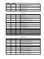
218M PLC address type is as follows:
Character
Signal description
X
Machine tool→PLC(64 byte)
Y
PLC→machine tool (64 byte)
F
CNC→PLC(64 byte)
G
PLC→CNC(64 byte)
R
Internal relay(512 byte)
D
Data register (0~255)
DC
Counter preset data register
C
Meter (0~127)
A
PLC message request signal
T
Timer (0~127)
DT
Timer preset data register
K
Keep relay(64 byte)
3.1
Length
INT8U
INT8U
INT8U
INT8U
INT8U
INT8U
INT8U
Addresses from Machine tool to PLC(X)
X addresses of GSK218M PLC are divided into two:
1. X addresses are assigned to IO input interface of XS43, XS44 and XS45.
2. X addresses are assigned to the input press keys on MDI panel.
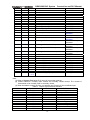
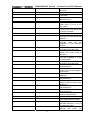
3.1.1
Assignment of IO module X address
The addresses are from X0 to X5. Its type is INT8U, 48 types. They are assigned to three IO input
interface of XS 43, XS44 and XS45.
The signal specification of X addresses can be customized by customer according to the actual
operation. X addresses are used to connect the machine tool with the ladder. For the initial
definition of input address, see Connection.
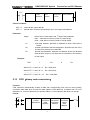
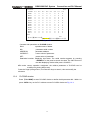
3.1.2
Assignment of MDI panel X address
The addresses are from X20 to X30, 11bytes. They correspond to the press keys on MDI panel,
11
GSK218M CNC System
Connection and PLC Manual
and their signal definitions cannot be changed by user.
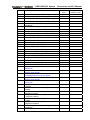
Addresses and press keys are as follows:
Input key on operator panel
PLC address
Edit mode
X20.0
Auto mode
X20.1
MDI mode
X20.2
Machine zero return mode
X20.3
Single step mode
X20.4
Manual mode
X20.5
MPG mode
X20.6
DNC mode
X20.7
Skip
X21.0
Single block
X21.1
Dry run
X21.2
Miscellaneous(M, S, T) lock
X21.3
Machine lock
X21.4
Selection stop
X21.5
Program restart
X21.6
Spindle CW
X22.0
Spindle stop
X22.1
Spindle CCW
X22.2
Spindle negative override
X22.3
Spindle override cancel
X22.4
Spindle positive override
X22.5
Spindle jog
X22.6
Lubrication
X23.0
Cooling
X23.1
Chip removal
X23.2
Cycle start
X23.6
Feed hold
X23.7
Feedrate positive override
X24.0
Feedrate override cancel
X24.1
Feedrate negative override
X24.2
Rapid
X24.7
/ 0.001
X26.0
Rapid 25%
/ 0.01
X26.1
Rapid 50%
/ 0.1
X26.2
Rapid F0
Rapid 100%
/
Manual feed axis
X26.3
1
X27.0
+X
Manual feed axis +Y
X27.1
Manual feed axis +Z
X27.2
12
GSK218M CNC System
3.2
Connection and PLC Manual
Manual feed axis +Th4
X27.3
USER1
X27.4
Manual feed axis -X
X28.0
Manual feed axis -Y
X28.1
Manual feed axis -Z
X28.2
Manual feed axis -Th4
X28.3
USER2
X28.4
USER3
X28.7
Spindle orientation
X29.0
Tool magazine zero return
X29.1
Tool clamp/ release
X29.2
Tool magazine CW
X29.3
Tool magazine CCW
X29.4
tool infeed
X29.5
tool retraction
X29.6
Tool change manipulator
X29.7
Overtravel release
X30.0
Address (Y) from PLC to machine tool
Y addresses of GSK218M PLC are divided into two:
1. Y addresses are assigned to IO input interface of XS40, XS41 and XS42.
2. Y addresses are assigned to the indicators on MDI panel.
3.2.1 Assignment of IO module Y address
a)
The addresses are from Y0 to Y5. Its type is INT8U, 48 types. They are assigned to three
IO input interface of XS40, XS41 and XS42.
The signal specification of Y addresses can be customized by customer according to the
actual operation. Y addresses are used to connect the machine tool with the ladder. For
the initial definition of input address, see Connection.
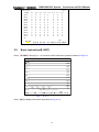
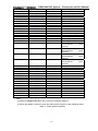
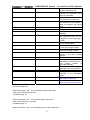
3.2.2
Assignment of IO module Y address
The addresses are from Y12 to Y19, 8 bytes. They correspond to the indicators on MDI panel, and
their signal definitions cannot be changed by user.
Addresses and indicators are as follows:
Output key on operator panel
PLC address
Edit key indicator
Y12.0
Auto key indicator
Y12.1
MDI key indicator
Y12.2
Machine zero return indicator
Y12.3
13
GSK218M CNC System
Connection and PLC Manual
Single step key indicator
Y12.4
Manual key indicator
Y12.5
MPG key indicator
Y12.6
DNC key indicator
Y12.7
Spindle CW indicator
Y13.0
Spindle CCW indicator
Y13.1
Spindle override cancel indicator
Y13.2
X machine zero return indicator
Y13.3
Y machine zero return indicator
Y13.4
Z machine zero return indicator
Y13.5
TH4 machine zero indicator
Y13.6
DEF(program restart) indicator
Y13.7
Skip indicator
Y14.0
Single block indicator
Y14.1
Dry run indicator
Y14.2
Miscellaneous(M, S, T) lock indicator
Y14.3
Machine tool lock indicator
Y14.4
Machine tool lamp indicator
Y15.0
Lubrication indicator
Y15.1
Cooling indicator
Y15.2
Chip removal indicator
Y15.3
Feedrate override cancel indicator
Y16.0
Rapid switch indicator
Y16.1
0.001/F0 indicator
Y16.2
0.01/25% indicator
Y16.3
0.1/50% indicator
Y16.4
1/100% indicator
Y16.5
Spindle orientation indicator
Y15.7
Tool magazine zero return indicator
Y16.0
Tool magazine CCW indicator
Y16.1
Tool magazine CW indicator
Y16.2
Tool magazine infeed indicator
Y16.3
Tool magazine retraction indicator
Y16.4
Tool magazine clamp indicator
Y16.5
Tool change manipulator indicator
Y16.6
USER3(tool change position)indicator
+X indicator
Y16.7
Y17.0
+Y indicator
Y17.1
+Z indicator
Y17.2
+TH4 indicator
Y17.3
USER1 indicator
Y17.4
-X indicator
Y18.0
-Y indicator
Y18.1
-A indicator
Y18.2
14
GSK218M CNC System
3.3
Connection and PLC Manual
-TH4 indicator
Y18.3
USER2 key indicator
Y18.4
Overtravel completion indicator
Y19.0
Feed hold indicator
Y19.1
Cycle start indicator
Y19.2
Tool magazine zero return indicator
Y19.3
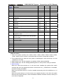
Address (G) from PLC to CNC
Addresses are from G0 to G63. Type: INT8U, 64 bytes.
For signals, see Volume Function.
Key signals on the operator panel
Key signal on operator panel
Edit mode
PLC address
G20.0
Auto mode
G20.1
MDI mode
Machine zero return mode
G20.2
G20.3
Single step mode
G20.4
Manual mode
G20.5
MPG mode
G20.6
DNC mode
Skip
G20.7
G21.0
Single block
G21.1
Dry run
G21.2
Miscellaneous (M,S, T) lock
G21.3
Machine tool lock
G21.4
Selection stop
G21.5
Program restart
Spindle CW
G21.6
G22.0
Spindle stop
G22.1
Spindle CCW
G22.2
Spindle negative override
Spindle override cancel
G22.3
G22.4
Spindle positive override
G22.5
Spindle jog
G22.6
Lubrication
G23.0
Cooling
Chip removal
G23.1
G23.2
Cycle start
G23.6
Feed hold
G23.7
Feedrate positive override
G24.0
Feedrate override cancel
G24.1
15
GSK218M CNC System
Connection and PLC Manual
Feedrate negative override
G24.2
Rapid switch
Rapid F0
G24.7
G25.0
Rapid 25%
G25.1
Rapid 50%
G25.2
Rapid 100%
G25.3
Incremental step 0.001
G26.0
Incremental step 0.01
Incremental step 0.1
G261
G26.2
Incremental step 1
G26.3
Manual feed axis +X
G27.0
Manual feed axis +Y
G27.1
Manual feed axis +Z
G27.2
Manual feed axis +Th4
G27.3
Manual feed axis -X
Manual feed axis -Y
G28.0
G28.1
Manual feed axis -Z
G28.2
Manual feed axis -Th4
G28.3
Spindle orientation
G29.0
Tool magazine zero return
G29.1
Tool clamp/release
G29.2
Tool magazine CW
G29.3
Tool magazine CCW
G29.4
Tool infeed
G29.5
Tool retraction
G29.6
Tool change manipulator
G29.7
Overtravel release
G30.0
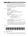
Bit signal of G63 byte is used by the internal of the system, G63.0 and G63.1 should be carefully
specified when the user compiles M and S instructions.
3.4
Address (F) from CNC to PLC
Addresses are from F0 to F63. Type: INT8U, 64 bytes.
For signals, see Volume Function.
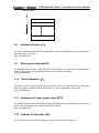
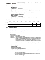
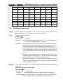
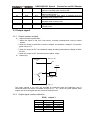
3.5
Internal relay address(R)
The address area is cleared to zero when the power is turned on.
Type: INT8U, with 512 bytes.
R255.0~R255.7 are used by the system, cannot be defined by the user.
16
GSK218M CNC System
Connection and PLC Manual
Address number
7
6
5
4
3
2
1
A
C
0
R relay area
R511
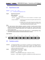
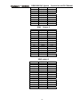
3.6
Address of keep relay(K)
The area is used as keep relays and PLC parameters. In each modal, the following number of
bytes can be used. Since this area is nonvolatile, the content of the memory do not disappear even
when the power is turned off. K000~~K005 are used by the system, and cannot be defined by the
user.
Type: INT8U, with 64 bytes.
Address number
7
6
5
4
3
2
1
0
K0
K1
K relay area
K255
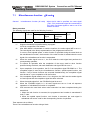
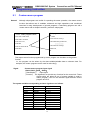
3.7
Addresses(A) for message selection displayed on CRT
The address area is cleared to zero when the power is turned on.
Type: INT8U, with 32 bytes.
17
GSK218M CNC System
Connection and PLC Manual
Address number
7
6
5
4
3
2
1
0
A0
A1
A31
3.8
Address of meter(C)
The area is used as storing current counting value in meter. The address area is cleared to zero
when the power is turned on.
Type: 128 addresses.
3.9
Meter preset address(DC)
The address area is used to store the meter preset value. Since this area is nonvolatile, the
content of the memory do not disappear even when the power is turned off.
Type: 128 addresses.
3.10
Timer addresses(T)
The area is used as storing current counting value in timer. The initial data is the preset value
when the system is turned off. When preset value is 0, the current data is preset value.
Type: 128 addresses.
3.11
Addresses of timer preset value(DT)
The address area is used as storing preset value. Since this area is nonvolatile, the content of the
memory do not disappear even when the power is turned off.
Type: 128 addresses.
3.12
Address of data table(D)
The content of the memory do not disappear even when the power is turned off.
18
GSK218M CNC System
Connection and PLC Manual
Type: 256 addresses. D240~247 are for tool magazine. D240~247 are used by the system and
cannot be defined.
3.13
Label address(L)
Label addresses are used to specify jump destination labels and LBL labels in JMPB instructions.
Range: 0~99
3.14
Subprogram numbers(P)
Subprogram numbers are used to specify jump destination subprogram labels and SP instruction
subprogram labels in CALL instruction.
Range: 0~99
19
GSK218M CNC System
4
Connection and PLC Manual
PLC Basic Instruction
Designing a sequence program begins with writing a ladder diagram. The ladder diagram is written
using relay contact symbols and functional instruction code. Logic written in the ladder diagram is
entered as a sequence program in the Programmer. There are two sequence program entry
methods. One is the entry method with the mnemonic language (PLC instructions such as RD,
AND, OR). The other is the relay symbols of the ladder diagram. When the relay symbol method is
used, the ladder diagram format can be used and programming can be performed without
understanding the PLC instruction format.
Actually, however, the sequence program entered by the relay symbol method is also internally
converted into the instruction corresponding to the PLC instruction.
The basic instructions are often used when the sequence program is designed, and the execute
one-bit operation.
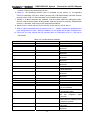
GSK218M basic instructions are as follows:
Instruction
Function
RD
Shifts left the content by one bit in register and sets the state of a
specified signal in ST0.
Shifts left the content by one bit in register and sets the logic state
of a specified signal in ST0.
Outputs the results of logic operation to a specified address.
RD.NOT
WRT
WRT.NOT
Inverts the results of logical operations and output it to a specified
address.
Induces a logical product.
AND
AND.NOT
Inverts the state of a specified signal and induces a logical
product.
Induces a logical sum.
OR
OR.NOT
Inverts the state of a specified signal and induces a logical sum.
OR._STK
Sets the logical sum of ST0 and ST1, and shifts the stack register
right by one bit.
Sets the logical product of ST0 and ST1, and shifts the stack
register right by one bit.
AND.STK
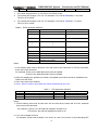
4.1
RD, RD.NOT, WRT, WRT.NOT
Instructions and functions
Instruction
Function
RD
Shifts left the content by one bit in register and sets the state of a
specified signal in ST0.
Shifts left the content by one bit in register and sets the logic state of
a specified signal in ST0.
Outputs the results of logic operation to a specified address.
RD.NOT
WRT
WRT.NOT
Inverts the results of logical operations and output it to a specified
address.
20
GSK218M CNC System
Connection and PLC Manual
Instruction specifications:
z WRT, WRT. NOT are the output relay, internal relay instructions. They cannot be used to
input relay.
z The parallel WRT instruction can be continuously used many times.
Programming
RD
X002.1
WRT Y003.7
RD.NOT F100.3
WRT G120.0
4.2
AND, AND.NOT instructions
Instructions and functions
Instruction
AND
AND.NOT
Function
Induces a logical product.
Inverts the state of a specified signal
and induces a logical product.
Instruction specifications:
z AND, AND NOT can connect with one contact in serial. The serial contact numbers are not
limited and they can be used many times.
Programming
RD
X002.1
AND.NOT F100.3
AND X008.6
WRT Y003.7
4.3
OR, OR.NOT instructions
Instructions and functions
Instruction
OR
OR.NOT
Function
Induces a logical sum.
Inverts the state of a specified signal
and induces a logical sum.
Instruction specification:
z OR, OR_NOT can connect with one contact in parallel.
z OR, OR.NOT begins from their step, which can connect with the for the mentioned step in
parallel.
21
GSK218M CNC System
Connection and PLC Manual
Programming:
RD
X002.1
OR._NOT F100.3
WRT Y003.7
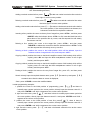
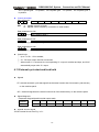
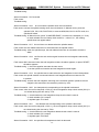
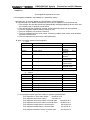
4.4
OR. STK instruction
Instruction and function:
Instruction
OR. STK
Function
Sets the logical sum of ST0 and ST1, and shifts the
stack register right by one bit.
Instruction specification:
z OR.STK a sole instruction without other address.
Programming
RD
X002.1
AND.NOT X002.2
RD.NOT F100.3
AND F100.6
OR.STK
RD R022.1
WRT Y003.7
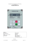
Node N1
As the above figure, there are three branch circuit ①,②,③ from left bus to the node N1, among
which ①,② is circuit block in series; when there is the serial circuit block in the parallel from the
bus to node or between nodes, the following branch end uses RD instruction except for the first
branch. The branch ③ is not serial circuit block to use OR instruction.
OR.STK and AND.STK are instructions without operation components, indicating the OR, AND
relationship between circuit blocks.
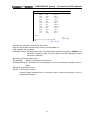
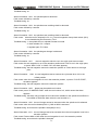
4.5
AND.STK instruction
Instruction and function
Instruction
AND.STK
Function
Sets the logical product of ST0 and ST1, and shifts the
stack register right by one bit.
Instruction specification
z When the branch loop (parallel loop block) is connected to the previous loop in series, use
AND.STK instruction. The starting point of branch uses RD, RD.NOT instruction, after the
parallel loop block ends, AND,STK instruction is connected to previous loop in series.
z AND.STK a sole instruction without other address.
Programming
22
GSK218M CNC System
Connection and PLC Manual
RD
X002.1
OR.NOT F100.3
OR.NOT X011.0
RD
R100.0
AND.NOT R100.3
RD
G003.3
AND R009.7
OR.STK
AND.STK
WRT Y003.7
Block ②
Block ①
←⑴
←⑵
As the above figure and instruction list, ⑴RD reports the circuit block in series is connected
parallel ⑵AND.STK reports the block ① and ② are connected in series.
23
GSK218M CNC System
Connection and PLC Manual
5 PLC Functional Instructions
Basic instructions such as controlling operations of machine tool are difficult to program, therefore,
functional instructions are available to facilitate programming.
218M functional instruction as follows:
No.
Instruction
Processing
1
END1
2
END2
3
CALL
End of a first-level ladder
program
End of a second-level ladder
program
Calling subprogram
4
SP
Subprogram
5
SPE
End of subprogram
6
SET
Set
7
RST
Reset
8
JMPB
Label jump
9
LBL
Label
10
TMR
Timer
11
CTR
Binary meter
12
DEC
Binary decoding
13
COD
Binary code conversion
14
COM
Common line control
15
COME
End of common line control
16
ROT
Binary rotation control
17
SFT
Register shift
18
DIFU
Rising edge check
19
DIFD
Failing edge check
20
COMP
Binary comparison
21
COIN
Coincidence check
22
MOVN
23
XMOV
Transfer of an arbitrary
number of bytes
Indexed data transfer
24
DSCH
Binary data search
25
ADD
Binary addition
26
SUB
Binary subtraction
27
ANDF
Functional AND
28
ORF
Functional OR
29
NOT
Logical Negation
30
EOR
Exclusive OR
24
GSK218M CNC System
Connection and PLC Manual
st
5.1
END1(1 level sequence program end)
Function:
Must be specifies once in a sequence program, either at the end of the 1st level sequence, or at the
beginning of the 2nd level sequence when there is no 1st level sequence. It can write 100 steps.
Format:
END1
END2(2nd level sequence program end)
5.2
Function
Specify at the end of 2nd level sequence.
Format:
END2
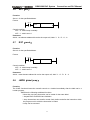
5.3
CALL(call subprogram)
Function
Call a specified subprogram.
CALL has the following additional functions:
*
More than one call instructions can call the same subprogram.
*
Calling instruction can be nested.
*
Cannot call subprogram in 1st level sequence program.
*
Subprogram must be written after END2.
Format:
ACT
CALL
Subprogram number
Control condition:
ACT=0,execute the next instruction behind CALL.
ACT=1,call subprogram which number is specified.
Parameter:
Subprogram: specifies the subprogram number of a subprogram to be coded following this
instruction. Range: 0~99.
25
GSK218M CNC System
5.4
Connection and PLC Manual
SP(Subprogram)
Function:
The SP functional instruction is used to create a subprogram. A subprogram number is specified
as a subprogram name. SP is used with the SPE functional instruction to specify the subprogram
range.
Note:
1. A subprogram must be written after END2.
2. Another subprogram cannot be nested into a subprogram.
Format:
SP
Subprogram number
Parameter:
Subprogram number: specifies the subprogram label of a subprogram to be coded following this
instruction. Range: 0~99.
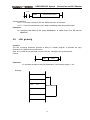
5.5
SPE(subprogram end)
Function:
* it is used to specify the range of subprogram when SPE is used with the S P.
* the control will return to the main program which called the subprogram when the
instruction is executed.
* the subprogram is written after END2.
Format:
SPE
Example:
CALL
P33
END2
SP
P33
SPE
26
GSK218M CNC System
5.6
Connection and PLC Manual
SET(set)
Function:
Set to 1 for the specified address.
Format:
ACT
SET
Add.b address
Control condition:
ACT=0,add.b keep invariably.
ACT=1,add.b set to1.
Parameter:
Add.b:set element address bit can be the output coil, Add= Y,G,R,K,A.
5.7
RST(reset)
Function:
Set to 0 for the specified address.
Format:
ACT
RST
Add.b address
Control condition:
ACT=0,add.b keep invariably.
ACT=1,add.b set to1.
Parameter:
Add.b:reset element address bit can be the output coil, Add= Y,G,R,K,A.
5.8
JMPB(label jump)
Function:
The JUMP functional instruction transfer control to a Ladder immediately after the lable set in a
Ladder program.
JMPB has the following additional functions:
* More than one jump instruction can be coded for the same label.
* Jumped END1 and END2 are forbidden.
* Jump instructions can transfer control freely before and after the instruction within
the program unit in which the instruction is coded.
* Jump can be executed.
27
GSK218M CNC System
Connection and PLC Manual
Format:
ACT
JMPB
Jump destination label
Control conditions:
ACT=0: The next instruction after the JMPB instruction is executed.
ACT=1: Control is transferred to the Ladder immediately after the specified label.
Parameter:
Lx: specifies the label of the jump destination. A value from 0 to 99 can be
specified.
5.9
LBL(Label)
Function:
The LBL functional instruction specifies a label in a ladder program. It specifies the jump
destination for JMPB functional instruction.
Note: one Lx label is only specified one time with LBL. Otherwise, the system alarms.
Format:
LBL
Label
Parameter:
Lx: specifies the label of the jump destination. Label number range: 0~99
Example:
JMPB
L33
LBL
L33
JMPB
L33
28
GSK218M CNC System
5.10
Connection and PLC Manual
TMR(timer)
Function:
This is an on-delay timer.
Format:
ACT
TMR
TIMER number
(W)
Control condition:
ACT=0: turns off the timer relay.
ACT=1: initiates the timer. i.e. timing from 0.
Detailed functions:
ACT
Address.b
TIME
Parameter:
TIMER
:timer serial number is named with xxx which are numbers (0~127).
Output:
W
: output coil. W=1 when the output reaches the preset value. W=0 when the output does not
reach the preset value.
Note:
The setting time is every 4ms for the timer.
The timer can be set via 【TMR】in【PLCPAR】.
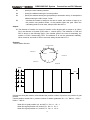
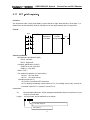
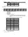
5.11
CTR(binary counter)
Function:
The data in the counter are binary and their functions are as follows:
1) Preset counter
Preset the count. It outputs a signal when the preset count is reached.
2) Ring counter
Upon reaching the preset count, returns to the initial value by issuing another counter signal.
3) Up/down counter
The count can be either up or down.
4) Selection of initial value
Its initial value is 0 or 1.
29
GSK218M CNC System
Connection and PLC Manual
Format:
CNO
CTR
METER
(W)
UPDOWN
RST
TT
ACT
C number
Control condition:
Specifies the initial value(CN0):
CN0=0: begins the value of the counter with 0.
CN0=1 begins the value of the counter with 1.
Specify up or down counter (UPDOWN):
UPDOWN=1: Up counter
UPDOWN=0: Down counter
Reset (RST):
RST=0: release reset.
RST=1: enable reset. When W=0, the integrated value is reset to the initial value.
RST is set to 1 only when reset is required.
Count signal(ACT):
ACT=1:count is made by catching the rise of ACT.
ACT=0:counter does not operate. W does not change.
Parameter:
METER:specifies the counter serial number with xxx which are numbers (0~127).
Output:
W:coil output. W=1 when the counter reaches the preset value.
Note: When the counter is rise edge to count, and the counter number is duplicated, or falls outside
the valid range, the operation will be unpredictable.
The timer can be set via 【TMR】in【PLCPAR】.
5.12
DEC(binary decode)
Function:
DEC can decode binary code data. Outputs 1 when the eight-digit BCD signal is equal to a
specified number, and 0 when not.
It is mainly used to decode M or T function.
30
GSK218M CNC System
Connection and PLC Manual
Format:
ACT
DEC
Length
Format
destination
S1 code
Data
address
S2
decode
designation
number
S3
decode
result address
Control condition:
ACT=0 :
resets all the output data bit.
ACT=1 :
decode data. Results of processing is set in the output data address.
Parameter:
length
:
Set the size of code data to the 1st digit of the parameter.
0001:code data is in binary format of 1 byte length.
0002:code data is in binary format of 2 byte length.
S1
: code data address. Specifies an address at which code data is
stored.
: number specification decode designation. Specifies the first of the
8 continuous numbers to be decoded.
: decode result address. Specifies an address where the decoded
result shall be output. A one-byte area is necessary in the memory
for the output.
S2
S3
Example:
DEC
1
F10
8
R4
When ACT=1 and F10=8, R4=0000,0001;
When ACT=1 and F10=9, R4=0000,0010;
………………………….
When ACT=1 and F10=15, R4=1000,0000;
5.13
COD(binary code conversion)
Function:
COD instruction automatically creates a table with corresponding size used for user inputting
conversion table data when it inputs the data capacity. Each table has 10 lattices and if it is not
divided by 10, count the lattices by its quotient adding 1, but its capacity data does not change.
Format:
RST
ACT
COD
Length1
Format
destination
Length2
Conversion
table
capacity
31
S1
conversion
input data
address
S3
conversion
output
data
address
(W)
GSK218M CNC System
Connection and PLC Manual
S1
0
1
2
.。。
。。
。。
N-1
S2
XXX
YYY
AAA
.。。
。。
。。
UUU
Control conditions:
Reset (RST):
RST=0: do not reset.
RST=1: reset error output W.
Activate instruction (ACT):
ACT=0 : do not execute COD.
ACT=1
: execute COD. Take value of “Conversion input data address(S1)” as
the table number of conversion table, take out of 1 conversion data
which corresponds to the table number from the conversion table,
output the output address used for the conversion data (S2).
Conversion table
Conversion input
data address
(S1)
Table No. Conversion data
1
0
XXX
1
YYY
2
AAA
。。。
.。。
。。
。。
N-1
UUU
Conversion input data
YYY
address
(S2)
Parameter:
Length1 :designates binary numerical size in the conversion table.
1:Numerical data is binary 1-byte data.
2:Numerical data is binary 2-byte data.
length2 : Number of conversion table data. 100 data can be made. 100 bytes when
designating 1 byte format, and 100 words when 2 byte format. All number is
at most 512 bytes in COD conversion table.
1:2 bytes
2:4 bytes
3:8 bytes
4:16 bytes
5:32 bytes
6:64 bytes
7:128 bytes
8:256 bytes
S1 :Data in the conversion data table can be taken out by specifying the table number.
The address specifying the table number is called conversion input data address,
and 1-byte memory is required from the specified address.
S2 :Conversion data output address. Memory of the byte length specified in the format
designation is necessary from the specified address.
Output:
If there are any abnormality when executing the CODB instruction, W=1, and error will be
32
GSK218M CNC System
Connection and PLC Manual
output.
Note: Size of the conversion data table is maximum 256. This conversion data table is
programmed between the parameter conversion data output address of this instruction and
the error output(W).
5.14
COM (common line control)
Function:
This function can be used for specifying the number of coil only on the PLC-SB/SC. If the common
line end instruction is not specified, the system will alarm.
Format:
ACT
COM
(W)
COM execution range
(W)
COME
Control condition:
ACT=0: The specified number of coils or the coils within the region specified are
unconditionally turned off (W=0).
ACT=1: No processing is performed.
Note:
1. In the range specified with a COM instruction, no additional COM instruction can be
specified.
2. the coil for WRT.NOT in the range specified with a COM instruction is singly set to 1 when
COM ACT=0.
3. do not use the function block between COM and COME, otherwise, the system will alarm.
5.15
COME (common line control end)
Function:
The instruction reports the division in the region specification of the common line control instruction
(COM). This instruction cannot be used alone. It must be used together with the COM instruction.
Format:
COME
33
GSK218M CNC System
5.16
Connection and PLC Manual
ROT(Binary rotation control)
Function:
Controls rotors, such as the toolpost, rotary table, etc., and is used for the following functions.
1. Selection of the rotation direction via the shorter path.
2. Calculation of the number of steps between the current position and the goal position;
calculation of the position on position before the goal to the number of steps up to one
position before the goal.
3. Calculation of the position one position before the goal or of the number of steps up to one
position before the goal.
Format:
CNO
DIR
ROT
S1
Rotor
indexing
address
S2
Current
position
address
POS
S3
Goal
position
address
S4
Calculating
result
output
address
(W)
INC
ACT
Control conditions:
Specify the starting number of the rotor(CN0):
CNO=0: begins the number of the position of the rotor with 0.
CNO=1: begins the number of the position of the rotor with 1.
Select the rotation direction via the shorter path or not: (DIR):
DIR=0: no direction is selected. The direction of rotation is only forward.
DIR=1: selected. The direction of rotation is forward/backward.
Specify the operating conditions (POS):
POS=0: calculate the goal position.
POS=1: calculates the position one position before the goal position.
Specify the position or the number of steps(INC):
INC=0: calculates the number of the position. If the position one position before
the goal position is to be calculated, specify INC=0 and POS=1.
INC=1: calculates the number of steps. If the difference between the current
position and the goal position is to be calculated, specify INC=1 and
POS=0.
Execution instruction (ACT):
ACT= 0:the ROT instruction is not executed. W does not change.
ACT=1:executed. Normally, set ACT=0. If the operation results are required,
set ACT=1.
34
GSK218M CNC System
Connection and PLC Manual
Parameter:
S1
: specify the rotor indexing number.
S2
: specify the address storing the current position.
S3
: specify the address storing the goal position(or instruction value), for example the
S4
address storing the CNC output T code.
: calculate the number of steps for the rotor to rotate, the number of steps up to
the position one position before, or the position before the goal. When the
calculating result is to be used, always check that ACT=1.
Output:
W: The direction of rotation for control of rotation via the shorter path is output to W. When
W=0, the direction is forward (FOR) when 1, reverse (REV). The definition of FOR and
REV is shown in the following figure. If the number given to the rotor is ascending, the
rotation is FOR; if descending, REV. The address of W can be determined arbitrarily.
When, however, the result of W is to be used, always check that ACT=1.
Example:
Rotor rotation direction:
Current position
Position D
Backward
Forward
Position A
Position C
Position B
RNO
ROT
12
S2
S3
S4
(W)
DIR
POS
INC
ACT
Perform the short path rotation, and calculate the position number of previous one position of goal
position.
Current position number S2=1, position number of rotation graduation S1=12,RNO=1,DIR=1
POS=1,INC=0:
When S3=10 goal position is A, and ACT=1, S4=11,W=1.
When S3=8 goal position is B, and ACT=1, S4=9,W=1.
When S3=5 goal position is C, and ACT=1, S4=4,W=0.
35
GSK218M CNC System
Connection and PLC Manual
When S3=3 goal position is D, and ACT=1, S4=2,W=0.
5.17
SFT(shift register)
Function:
The instruction shifts 1-byte (8-bit) data by a bit to the left or right. Note that W=1 when data “1” is
shifted from the left extremity (bit 8) in left shift or from the right extremity (bit 0) in right shift.
Format:
DIR
SFT
CONT
S1
Address of
shift data
Length
Format
designation
(W)
RST
ACT
Control conditions:
Shift direction specification (DIR)
DIR=0: Left shift
DIR=1: Right shift
Condition specification (CONT)
CONT=0: do not cycle shift
CONT=1: cycle shift
Reset(RST)
The shifted out data(W=1) is reset (W=0).
RST=0: W is not reset.
RST=1: W is reset (W=0).
Actuation signal (ACT)
ACT=0: do not execute SFT instruction.
ACT=1:shifting processing is done when ACT=1. For shifting one bit only, execute an
instruction when ACT=1, and then, set ACT to 0.
Parameters:
S1
:sets shift data addresses. These designated addresses require a continuous 1-byte
memory for shift data.
Length :a 4-bit number, and its definition is as follows:
O
OOO
L: bit shifts every bit
A:shift status
36
GSK218M CNC System
Connection and PLC Manual
L :range: 0~8.
A :bit parameter. A=0: When ACT=1 is shifting, the shift period is one bit.
A=1: ACT is taken as pulse signal, it is 1 from 0, shift one
bit.
Output:
W
:
W=0: “1” was not shifted out because of the shift operation.
W=1: “1” was shifted out because of the shift operation.
5.18
DIFU(rising edge check)
Function:
The DIFU instruction sets the output signal to 1 for one scanning cycle on a rising edge of the
input signal.
Format:
ACT
L : rising edge number
DIFU
(W)
Control condition:
Input signal: On a rising edge(01)of the input signal, the output signal is set to 1.
Output signal: The output signal level remains at 1 for one scanning cycle of the ladder level
where this functional instruction is operating.
Parameter: Rising edge number
Parameter :
L
:rising edge number, range 0~255. Another DIFU instruction or DIFD
instruction in the ladder uses the same number, the system will alarm.
Operation:
1
5.19
2
3
4
Execution period
DIFD(falling edge check)
Function:
The DIFD instruction set the output signal to 1 for one scanning period on a falling edge of
the input signal.
Format:
ACT
DIFD
L: falling edge number
37
(W)
GSK218M CNC System
Connection and PLC Manual
Control conditions:
Input signal: on a falling edge(10)of the input signal, the output signal is set to 1.
Output signal: the output signal level remains at 1 for one scanning period of the ladder level
where this functional instruction is operating.
Parameter:
L
:
rising edge number, range 0~255. Another DIFU instruction or DIFD instruction in
the ladder uses the same number, the system will alarm.
Operation:
1
5.20
2
3
4
Execution period
COMP(binary comparison)
Function:
Compares binary values. Specifies enough byte to store the input data and the comparison data in
the memory.
Format:
ACT
COMP
Length
Designation
format
S1 input data S2
address
comparison
data
address
(W)
Control conditions:
ACT=0: The COMP instruction is not executed. W does not alter.
ACT=1: The COMP instruction is executed.
Parameter:
Length:specification format( constant or address) and data length(1 or 2 bytes) for the
input data.
O
O
Specification of format
0:Constant
1:Address
Specification of data length
1:1 byte length data
2:2 byte length data
S1, S2: content of comparison source 1 and comparison source 2. It can be
constant and also be address number.
38
GSK218M CNC System
Connection and PLC Manual
Address number: R, X, Y, F, G, K, A, D, T, C.
Output:
W=0: input data>comparison data
W=1: input data ≤comparison data
5.21
COIN(coincidence check)
Function:
Checks whether the input value and comparison value coincide.
Format:
ACT
COIN
Length
format
S1
Input
value
S2
Comparison
value address
(W)
Control conditions:
ACT=0,the COIN instruction is not executed. W does not change.
ACT=1,the COIN instruction is executed.
Parameter:
Length:specification format( constant or address) and data length(1 or 2 bytes) for the
input data.
O
O
Specification of data length
1:1 byte length data
2:2 byte length data
Specification of format
0:Constant
1:Address
S1
:
The input data can be specified as either a constant or an address storing it.
S2
:
address storing of comparison data
:
W=0: input value ≠comparison value
Output:
W
W=1: input value=comparison value
5.22
MOVN(transfer of data)
Function:
The MOVN instruction transfers data from source address and a specified binary data to a
39
GSK218M CNC System
Connection and PLC Manual
Length transfer S1 transfer
byte number
source
address
S2 transfer
destination
address
specified destination address.
Format:
MOVN
ACT
(W
)
Control condition:
ACT=0: No data is transferred.
ACT=1: The byte of specified number is transferred.
Parameter:
Length
transferred byte number.
:
S1
:
stating byte of address or constant of source data.
Selecting transfer format according to S1:
1. S1 is constant: if S2 is single byte address, S1 in byte unit is copied to
address corresponding to Length byte which takes S2 as
the initial; if S2 is in word unit, it is copied in word address;
2. S1 is address: S1 and S2 transmit the data in byte in spit if S1 and S2
address classifications are matched.
S2
:
starting byte of destination address.
Example:
ACT
MOVN
2
S1
S2
(W)
1.When S1 is the constant 5 and S2 is R60,R60=00000101,R61=00000101
2.When S1 is the constant 5 and S2 is D60,D60=1285
3.When S1 is the constant 500 and S2 is D60,D60=62708
4.When S1 is the constant D50 and S2 is D60,D60=D50
5.23
XMOV(Binary index data transfer)
Function:
This function instruction instructs reading and rewriting of data in the data. The number of
data(table capacity) in the data table can be specified by specifying the address, thus allowing
change in table capacity even after writing the sequence program in the ROM.
40
GSK218M CNC System
Connection and PLC Manual
Format:
RW
XMOV Length
format
RST
ACT
S1
S2
S3
S4
Number Data table Address
Address storing
heading storing input table internal
of data of
the data
address /output data
number
table(table
capacity)
(W)
Control condition:
Specify the reading or rewriting (RW)
RW=0: data is read from the data table.
RW=1: data is written in the data table.
Reset(RST)
RST=0: release reset.
RST=1: reset W=0.
Execution instruction (ACT):
ACT=0
: The XMOV instruction is not executed. W does not change.
ACT=1
: The XMOV instruction is executed.
Parameter:
Length : Specify the data long.
1:1-byte long data.
2:2-byte long data.
S1
: Storage address of number of data table elements. The address is used to
store the data number of data table, its byte should correspond to the length
specified in Length format specification, and the effective range of number
of data table element is as follows with the byte length which set in Length1
format.
1 byte length:1 to 255.
2 byte length:1to 32767(Actually, set a value below the size of the D area.
S2
: Sets head address in the data table. The memory of (byte length )X (number
S3
of data table elements).
: Input/output data storage address. In case of the reading, set the address of
S4
the memory which stores a reading result a writing result. The memory
with the byte length which set in Length format specification is necessary.
: Index storage address. Set the address of the memory in which an index
value is stored. The memory with the byte length set in Length format
specification is necessary. When setting an index value above the value to
set in S1 storage address of number of data table elements, it causes an
error output W=1. Actually, the number of data table elements does not
exceed 255.
41
GSK218M CNC System
Connection and PLC Manual
Output:
The index value set in Index storage address exceeds the value set in S1, W=1, the reading or
writing of the data table isn’t executed.
W=0,No error.
W=1,Error found.
DSCH (binary data search)
5.24
Function:
The DSCH instruction is used to search the binary data in data table. The number of data (table
capacity) in the data table can be specified by specifying the address. Thus allowing change in
table capacity even after writing the sequence program in the ROM.
Format:
RST
DSCH
Length
Format
ACT
S1
Storage
address
of data
in data
table
S2
Data
table
head
address
S3
Search
data
address
S4
Output
address
of
search
result
(W)
Control conditions:
Reset(RST)
RST=0:Release reset.
RST=1:Reset. W=0.
Activation instruction (ACT):
ACT=0
: Do not execute DSCH instruction, W does not change.
ACT=1
: Execute DSCH instruction. If the search data is found, table number
where the data is stored will be output. If the search data is not found,
W becomes 1.
Parameter:
Length :Specifies data length
1:1-byte long data.
2:2-byte long data.
S1
: Storage address of number of data in data table. This address requires
memory of number of byte according to the format designation. Number of
data in the table is n+1(head number in the table is 0 and the last number is
n).
S2
: Data table head address.
S3
: Search data input address.
S4
: Search result output address. After searching, if search data is found, the
table number where the data is stored will be output. the searched table
number is output in this search result output address. This address
requires memory of number of byte according to the format designation.
42
GSK218M CNC System
Connection and PLC Manual
Output:
W=0,Search data found.
W=1,Search data not found.
5.25
ADD(addition)
Function:
This instruction performs binary addition between 1-, 2-byte data. In the operation result register,
operation data is set besides the numerical data representing the operation results. The required
number of bytes is necessary to store each augend, the added, and the operation output data.
Format:
RST
ADD
ACT
Length
Format
specification
S1
Augend
address
S2
Addend
address or
constant
S3
Operation
result(sum)
address
(W)
Control conditions:
Reset (RST):
RST=0: Release reset.
RST=1: Reset. W=1.
Activation instruction (ACT):
ACT=0 :Do not execute ADD. W does not change.
ACT=1 :Execute ADD.
Parameter:
Length
:Specifies data length(1 or 2 bytes) and the format for the addend(constant or
address).
O
O
Format specification
0:Constant
1:Address
Data length specification
1:1byte length data
2:2 bytes length data
S1
: Augend address.
S2
: Addend data specification determines the format of the addend.
S3
: Specify the address to contain the result of output operation.
Output:
W=0: Operation correct.
W=1: Operation incorrect.
When W=1, the result of addition exceeds the specified data length.
43
GSK218M CNC System
5.26
Connection and PLC Manual
SUB(binary subtraction)
Function:
This instruction executes the subtraction operation in the binary format of 1 or 2 bytes. In the
operation result register, operation data is set besides the numerical data representing the
operation. A required number of bytes is necessary to store the subtrahend, and the result.
Format:
RST
SUB
ACT
Length
Format
specification
S1
Menuend
address
S2
Subtrahend
address or
constant
S3
Operation
output
address
(W)
Control conditions:
Reset (RST):
RST=0: Release reset.
RST=1: Reset. W=0.
Activation instruction (ACT):
Parameter:
Length
ACT=0 :
Do not execute SUB. W does not change.
ACT=1 :
Execute SUB.
:Specifies data length(1 or 2 bytes) and the format for the subtrahend(constant or
address).
O
O
Format
specification
0:Constant
1:Address
Data length specification
1:1byte length data
2:2 bytes length data
S1
: Address containing the minend.
S2
: Specification determines the Length.
S3
: Specifies the address to contain the result of operation.
Output:
W=0: Operation correct.
W=1: Operation incorrect.
When W=1, the result of subtraction exceeds the specified data length.
44
GSK218M CNC System
5.27
Connection and PLC Manual
ANDF(functional and)
Function:
The ANDF instruction ANDFs the contents of address A with a constant( or the contents of address
B), and stores the result at address C.
Format:
ACT
ANDF
Length
Format
specification
S1
Address A
S2
Constant or
address B
S3
Address C
Control conditions:
ACT=0 : The ANDF instruction is not executed.
ACT=1 :
Parameter:
Length
The ANDF instruction is executed.
:Specify a data length (1 or 2 bytes), and an input data format(constant or address
specification).
O
O
Format specification
0:Constant
1:Address
S1
Data length specification
1:1byte length data
2:2 bytes length data
: Input data to be ANDed. The data that is held starting at this address and has
the data length specified in Length format specification is treated as input
data.
S2
:Input data to be ANDed with. When address specification is selected in format
S3
specification, the data that is held starting at this address and has the data
length specified in Length format specification is treated as input data.
: Address used to store the result of an ANDF operation. The result of and ANDF
operation is stored starting at this address, and has the data length specified
in Length format specification.
Example::
When address A and address B hold the following data:
Address A
1
1
1
0
0
0
1
1
Address B
1
0
1
0
1
0
45
1
0
GSK218M CNC System
Connection and PLC Manual
The result of the ANDF operation is as follows:
Address C
5.28
0
1
0
0
0
0
0
1
ORF(functional or)
Function::
The ORF instruction ORFs the contents of address A with a constant (or the contents of address
B),and stores the result at address C.
Format:
ACT
Length
Format
specification
ORF
S1
Address A
S2
Constant or
address B
S3
Address C
Control conditions:
ACT=0 : The ORF instruction is not executed.
ACT=1 :
The ORF instruction is executed.
O
O
Format
specification
0:Constant
1:Address
Data length specification
1:1byte length data
2:2 bytes length data
Parameter:
Length: Specify a data length(1 or 2 bytes), and an input data format(constant or address
specification).
S1 : Specify the input data to ORed. The data that is held starting at this address and has
the data length specified in Length format specification is treated as input data.
S2 : Input data to be ORed with. When address specification is selected in format
specification, the data that is held starting at this address and has the data length
specified in Length format specification is treated as input data.
S3 : Address used to store the result of an ORF operation. The result of an ORF
operation is stored starting at this address, and has the data length specified in
format specification.
Example:
When address A and address B hold the following data:
Address A
1
1
1
0
0
0
46
1
1
GSK218M CNC System
Address B
1
0
1
0
1
0
1
ORF operates are as follows:
Address C
1
1
1
1
0
1
1
1
5.29
0
Connection and PLC Manual
NOT(logical not)
Function:
The NOT instruction inverts each bit of the contents of address A, and stores the result at address
B.
Format:
ACT
S1
Address A
Length
NOT
Format
specification
S2
Address B
Control condition:
ACT=0: The NOT instruction is not executed.
ACT=1: The NOT instruction is executed.
Parameter:
Length
:Specifies a data length(1 or 2 bytes).
O
O
O
Data length specification
1:1 byte length data
2: 2 bytes length data
S1
:Input data to be inverted bit by bit. The data that is held starting at this address
and has the data length specified in Length format specification is treated as
input data.
S2
:Address used to output the result of a NOT operation. The result of a NOT
operation is stored starting at this address. And has the data length specified in
Length format specification.
Example:
When address A holds the following data:
Address A
1
1
1
0
0
0
1
1
1
0
0
The result of the NOT operation is as follows:
Address B
0
0
0
1
1
47
GSK218M CNC System
5.30
Connection and PLC Manual
EOR(exclusive or)
Function:
The EOR instruction exclusive-Ors the contents of address A with a constant( or the contents of
address B), and stores the result at address C.
Format:
ACT
EOR
Length
Format
specification
S1
Address A
S2
Constant or
address B
S3
Address C
Control conditions:
ACT=0 : The EOR instruction is not executed.
ACT=1 : The EOR instruction is executed.
Parameter:
Length
:Specify a data length (1 or 2 bytes) and an input data format(constant or address
specification).
O
O
Format specification
0:Constant
1:Address
Data length specification
1:1 byte length data
2:2 bytes length data
S1
: Input data to be exclusive-ORed. The data that is held starting at this address
S2
and has the data length specified in Length format specification is treated as
input data.
: Input data to be exclusive-ORed with. When address specification is selected
S3
report that specification, the data that is held starting at this address and has
the data length specified in Length format specification is treated as input data.
: Address used to store the result of an exclusive EOR operation. The result of an
exclusive EOR operation is stored starting at this address, and has the data
length specified in Length format specification.
Example:
When address A and B hold the following data:
Address A
1
1
1
0
0
0
1
1
1
0
1
The result of the exclusive EOR operation is as follows:
Address C
1
0
1
1
0
1
1
0
Address B
0
1
0
1
0
48
GSK218M CNC System
Connection and PLC Manual
6 Ladder Writing Limit
1. Sequence program must have END1 and END2 which are taken as the end marks of 1st
level and 2nd level sequence part, and END1 must be before END2.
2. They only support the parallel output and do not support the multi-level output.
3. The result output address in all basic instructions and output function instruction are not
set the following addresses:
(1) Counter preset address DC, timer preset address DT.
(2) K0~K5 address are occupied by the system.
(3) G63, R255 address are occupied by the system.
(4) X address on IO input interface and CNC→PLC F address.
The followings are the phrasing error, and the system will alarm.
(W)
(W)
(W)
(W)
(W)
(W)
(W)
49
GSK218M CNC System
Ⅱ
Connection and PLC Manual
Function
50
GSK218M CNC System
Connection and PLC Manual
1 Controlled Axis
1.1
Outputting of movement state of an axis
General
The movement state of each axis can be output to the PLC.
Signal
Axis moving signals
MV1~MV4 (F017#0~F017#3)
[Classification]
Output signal
[Function]These signals indicate that a controlled axis is moving.
MV1:X is moving.
MV2:Y is moving.
MV3:Z is moving.
MV4:A is moving.
[Output conditions]
The signals become 1 when:
z
The corresponding axis has started moving.
The signals become 0 when:
z
The corresponding axis has stopped moving.
Axis moving direction signals
MVD1~MVD4(F019#0~F019#3)
[Classification] Output signal
[Function]These signals indicate the movement direction of controlled axis.
MV1:movement direction of X.
MV2:movement direction of Y.
MV3:movement direction of Z.
MV4:movement direction of A.
[Output conditions] When parameter 0003#1~~0003#4 is 1:
“1” indicates the corresponding axes are negatively moving,
“0” indicates the corresponding axes are positively moving.
When parameter 0003#1~~0003#4 is 0:
“0” indicates the corresponding axes are negatively moving,
“1” indicates the corresponding axes are positively moving.
Caution:
These signals maintain their condition during a stop, indicating the direction of the axes’ movement
before stopping.
51
GSK218M CNC System
Connection and PLC Manual
Signal address
#7
#3
#2
#1
#0
F017
MV4
MV3
MV2
MV1
F019
MVD4
MVD3
MVD2
MVD1
1.2
Signal
#6
#5
#4
Servo ready signal
servo ready signal
SA(F000#6)
[Classification]
Output signal
[Function] After the servo is ready, SA signal becomes 1. For the axis with
absorption brake, release the brake when outputting the signal,
execute the brake when the system does not output the signal.
Signal address
#7
F000
#6
#5
#4
#3
SA
52
#2
#1
#0
GSK218M CNC System
Connection and PLC Manual
2 Preparation for Operation
2.1
Emergency stop
If you press Emergency Stop button on the machine operator’s panel, the machine
movement stops in a moment.
General
Red
Emergence stop
The button is locked when it is pressed, Although it varies with the machine too
builder, the button can usually be unlocked by twisting it.
Emergency stop signal
Signal
*ESP (G001.0 )
[Classification]
[Function]
Input signal
Activating an emergency stop signal stops the machine instantly.
[Operation] When the emergency stop *ESP becomes 1, the emergency stop is
applied to the machine and the CNC is reset.
Signal address
#7
#6
#5
#4
#3
Signal
#0
*ESP
G001
General
#1
*ESP
X001
2.2
#2
CNC overtravel signal
When the tool tries to move beyond the stroke end set by the machine tool limit
switch, the tool decelerates and stops as a result of tripping the limit switch, and an
Over TRAVEL is displayed. The signal can be output with an alarm.
Overtravel signal
+L1~+L4(G12#0~G12#3)
-L1~-L4(G13#0~G13#3)
[Classification] Input signal
[Function]Indicates that the control axis has reached its stroke limit. There are
53
GSK218M CNC System
Connection and PLC Manual
individual signals for each direction in every control axis.
The + /- in the signal name indicate the direction and the number
corresponds to the control axis.
。
+
L
1
1: No. X axis is at stroke limit
2. No. Y axis is at stroke limit
3. No. Z axis is at stroke limit
4. No. A axis is at stroke limit
+ positive overtravel
- negative overtravel
[Operations] “0”: the controlled unit operates as follows:
Automatic operation: If even one axis overtravel signal becomes, all
axes are decelerated to stop, an alarm is
given and operation is halted.
Manual operation: Only the axis whose overtravel signal has
become 0 is decelerated to a stop, and the
axis an be moved in the opposite direction.
Once the axis overtravel signal has become 0, the axis direction is registered.
Even if the signal returns to 1, it is not possible to move that axis in that direction
until the alarm is cleared.
Signal address
#7
#6
#5
#4
#3
#2
#1
#0
G012
+L4
+L3
+L2
+L1
G013
-L4
-L3
-L2
-L1
2.3
General
Signal
Alarm signal
When an alarm is triggered in the CNC, the alarm is displayed on the screen, and the
alarm signal is set to 1. If the voltage level of the memory backup battery falls to below
a specified level while the CNC is turned off, the battery alarm signal is set to 1.
Alarm signal
AL(F001#0)
[Classification]
Output signal
[Function] Alarm signal reports CNC is in an alarm state as follows:
a) P/S alarm
b) Overtravel alarm
c) Servo alarm
[Output conditions]These alarm signal is set to 1 when:
――The CNC is placed in the alarm state.
These alarm signals is set to 0 when:
――The alarm has been released by resetting the CNC.
Signal address
#7
#6
#5
#4
#3
#2
#1
#0
AL
F001
54
GSK218M CNC System
2.4
Signal
Connection and PLC Manual
Mode selection
mode check signal
F003#0~F003#7
[Classification] Output signal
[Function] Report the current selected operation mode
Signal address
F003
2.5
Signal
#7
#6
MZRO
MEDT
#5
#4
#3
#2
#1
#0
MMEM
MRMT
MMDI
MJ
MH
MINC
Status output signal
Rapid traversing signal
RPDO(F002#1)
[Classification]
Output signal
[Function] This signal indicates that a move instruction is being executed at the
rapid traverse.
[Output conditions:]
1: indicates an axis starts moving after rapid traverse has
been selected;
0: indicates that an axis starts moving after a federate
other than rapid traverse has been selected. This holds
true for both automatic and manual operation modes.
Cutting feed signal
CUT(F002#6)
[Classification]
Output signal
[Function] These signals indicate that the cutting feed is being performed by
automatic operation.
[Output conditions] These signals are 1 when:
Cutting feed is being performed by automatic operation (cutting
feed for linear interpolation, circular interpolation, helical
interpolation, thread cutting, skip cutting, or cutting in canned
cycle).
Note:
Do not output the signal in the state of feed hold.
Output the signal during the interlock or the feedrate override is set to 0.
Signal address
#7
F002
#6
#5
#4
#3
CUT
#2
#1
RPDO
55
#0
GSK218M CNC System
Connection and PLC Manual
3 Manual Operation
3.1
JOG feed/incremental feed
General
JOG feed
Incremental feed
In JOG mode, setting a feed axis and direction selection bit to 1 on the
machine operator’s panel moves the machine along the selected axis in the
selected direction.
In incremental feed mode, setting a feed axis and direction selection bit to 1 on
the machine operator’s panel moves the machine one step along the selected
axis in the selected direction. The minimum distance the machine moves, is
the least input increment. The step can be 10, 100, or 1000 times the least
input increment.
The only difference between JOG feed and incremental feed is the method of selecting the
feed distance. In JOG feed, the machine continues to be fed while the following signals
selecting the feed axis and direction are 1: +J1,-J1,+J2,-J2,+J3,-J3,etc. In
incremental feed, the machine is fed by one step. Using JOG feedrate override dial can
regulate JOG feedrate. The step distance can be selected by MPG feed movement
distance G026#0~G026#3.
Signal
Feed axis and direction selection signal
+J1~+J4(G27#0~G27#3)
-J1~-J4(G28#0~G28#3)
[Classification]
Input signal
[Function] In JOG feed or Incremental feed mode, select the required feed axis and
direction. +/- in the signal name indicates the feed direction, the number
corresponds to the controlled axis.
+
J
1
1: No. X axis is fed
2: No. Y axis is fed
3: No. Z axis is fed
4: No. A axis is fed
+ positive feed
- negative feed
[Operation]When the signal is set to 1, the control unit operate as follows:
When JOG feed or incremental feed is allowed, the control unit moves
the specified axis in the specified direction.
When the signal is set to 1 in JOG feed, the control unit continues to
feed that axis while the signal is set to 1.
In incremental feed, the control unit feeds the requested axis by the
step distance which is specified by the manual handle feed move
distance selection signal, then the axis stops. Even if the signal is set to
0 while the axis is being fed, the control unit does not stop moving.
56
GSK218M CNC System
Connection and PLC Manual
To feed the axis again set the signal to 0, then to 1 again.
Manual rapid traverse selection signal
RT(G024#7)
[Classification]
Input signal
[Function]Select the rapid traverse rate in JOG feed or incremental feed mode.
When the signal becomes 1, the control unit operates as follows:
[Use]
z The control unit executes the jog feed or incremental feed at a rapid
traverse rate. The rapid traverse override is validated.
z When the signal is switched from 1 to 0 or vice versa in jog feed or
incremental feed, the feedrate is decelerated until it reaches zero,
then increased to the specified value. During acceleration and
deceleration, the feed axis and direction selection signal can be kept
1.
Signal address
#7
#6
#5
#4
#3
#2
#1
#0
RT
G024
G027
+J4
+J3
+J2
+J1
G028
-J4
-J3
-J2
-J1
3.2
MPG/Step feed
General
In MPG/Step feed mode, the machine moves by rotating the manual pulse
generator(MPG)/Step. Select the axis along which the machine moves with the
MPG feed axis selection signal/axis move signal.
Signal
MPG/Incremental select signal
(G026#0~G026#3)
[Classification]
Input signal
[Function] When the signal selects the MPG feed, MPG generates the movement
distance of every pulse which also can select the movement distance per
step of incremental feed .
57
GSK218M CNC System
Connection and PLC Manual
4 Reference Point Return
4.1
Manual reference point return
General
In manual reference point return mode, the machine tool move in the specified
direction by setting the position parameter N0:7#3~#7 to execute the reference point
return. The selected axis on the panel reports the axis to execute the machine zero
return, which is not related to the move direction of axis.
The following signals are related to the manual reference point return:
Manual reference point return
Reference point return deceleration signal
DECX,DECY,DECZ,DECA
Reference point return completion signal
ZP1,P2, ,ZP3,ZP4
Reference point return completion signals
ZP1~ZP4(F016#0~F016#3)
[Classification]
Output signal
[Function] These signals report that the machine tool is at the reference point on a
ZP1
ZP2
ZP3
ZP4
controlled axis.
These signals correspond separately to all axes.
X axis reference point return completion signal.
Y axis reference point return completion signal.
Z axis reference point return completion signal.
A axis reference point return completion signal.
[Output conditions]When these signals becomes 1:
z Manual reference point return is completed and the current position
is in the in-position area.
z The automatic reference point return(G28) is completed and the
current position is in the in-position area.
z The reference point return check is completed and the current
position is in the in-position area.
When the signal becomes 0:
z The machine tool moves from the reference point.
z The emergency stop signal appears.
z The servo alarm appears.
Reference point return deceleration signal
DECX(X017#0)DECY(X017#1) DECZ(X017#2)DECA(X017#3)
[Classification]
Input signal
[Function]These signals decelerate the feedrate for manual reference point return to
a low feedrate.
58
GSK218M CNC System
4.2
Connection and PLC Manual
Reference point return check signal
2nd reference point permission signal
PREF20---PREF23 (G057#0----#3)
3rd reference point permission signal
PREF30---PREF33 (G058#0----#3)
4th reference point permission signal
PREF40---PREF43 (G059#0----#3)
[Type]
Input signal
[Function]When the signal is set to 1, the reference point return completion
signals(F42, F43, F44) are enabled.
These signals correspond separately to all axes.
PREF*0
X axis reference point check permission signal
PREF*1
Y axis reference point check permission signal
PREF*2
Z axis reference point check permission signal
PREF*3
A axis reference point check permission signal
2nd reference point return completion signal
ZP21---ZP24 (F042#0---#3)
3rd reference point return completion signal
ZP31---ZP34 (F043#0---#3)
4th reference point return completion signal
ZP41---ZP44 (F044#0---#3)
[Type] output signal
[Function]
These signals report that the machine tool is at the reference point on
a controlled axis.
These signals correspond separately to all axes
ZP*1
X axis reference point return completion signal
ZP*2
Y axis reference point return completion signal
ZP*3
Z axis reference point return completion signal
ZP*4
A axis reference point return completion signal
[Output conditions] the signal is enabled when it is the reference point check
permission signals(G57, G58, G59) become 1.
When these signals becomes 1:
z Manual reference point return is completed and the current position
is in the in-position area.
z The automatic reference point return(G30) is completed and the
current position is in the in-position area.
z The reference point return check is completed and the current
position is in the in-position area.
When the signal becomes 0:
z The reference point check permission signal (G57, G58,G59
become 0,
z The machine tool moves from the reference point.
z The emergency stop signal appears.
z The servo alarm appears.
59
GSK218M CNC System
4.3
Connection and PLC Manual
Area check signal
Area check signal
AQ1—AQ3 (F045#0---#2)
[Type]
Output signal
[Function]These signals report that the machine tool is at the reference point on a
controlled axis.
These signals correspond separately to all axes.
AQ1
X axis area check signal
AQ2
Y axis area check signal
AQ3
Z axis area check signal
[Output conditions]
When the machine is in the stored travel check 1( the data parameter
set P66~P75 the limit, and outside the stored travel check 2 (the data
parameter P76~P8 or program command can set the limit of this side),
the signal becomes 1, otherwise becomes 0.
Signal addresses
#7
#6
#5
#4
#3
#2
#1
#0
F016
ZP4
ZP3
ZP2
ZP1
F042
ZP24
ZP23
ZP22
ZP21
F043
ZP234
ZP33
ZP32
ZP31
F044
ZP44
ZP43
ZP42
ZP41
AQ3
AQ2
AQ1
F045
G017
DECA
DECZ
DECY
DECX
G057
PREF23
PREF22
PREF21
PREF20
G058
PREF43
PREF32
PREF31
PREF30
G059
PREF43
PREF42
PREF41
PREF40
Reference point return deceleration signal check
DECX(G017#0)DECY(G017#1) DECZ(G017#2)DECA(G017#3)
[Classification]Input signal
[Function]
These signals decelerate the feedrate for manual reference point
return to a low feedrate.
Reference point establishment signal
ZRF1~ZRF4(F060#0~F060#3)
60
GSK218M CNC System
Connection and PLC Manual
[Classification]Output signal
These signals report the system that the reference point has been
established.
These signals correspond separately to all-axis.
ZRF1 No. X axis reference point establishment
signal
ZRF2 No. Y axis reference point establishment
signal
ZRF3 No. Z axis reference point establishment
signal
ZRF4 No. A axis reference point establishment
signal
[Function]
[Output conditions] These signals become 1 when:
z The reference point has been established after manual reference
point return.
z When the reference point is established using the absolute-position
detector at initial power-on.
These signals become 0 when:
z The reference point is lost.
Signal address
#7
#6
#5
#4
#3
#2
#1
#0
F016
ZP4
ZP3
ZP2
ZP1
F060
ZRF4
ZRF3
ZRF2
ZRF1
G017
DECA
DECZ
DECY
DECX
#3
#2
#1
#0
MREF
F004
Parameter
#7
#6
#5
#4
JAX
0004
[Data Classification] bit
JAX Number of axes controlled simultaneously in JOG feed, manual rapid traverse
and manual reference point return.
0:multi-axis
1:single axis
#7
#6
#5
#4
#3
#2
#1
#0
ZRNx
0006
[Data type] bit-axis
61
GSK218M CNC System
Connection and PLC Manual
ZRNX When a instruction specifying the movement(except for G28) is issued in
automatic operation(MEM, RMT or MDI) before referencing is completed.
1: An alarm is generated (P/S alarm 224).
0: No alarm is generated.
Note:
0007
When the parameter is changed, the power supply must be turned off before operation
and then is turned on again.
#7
#6
#5
#4
#3
ZMI5
ZMI4
ZMIz
ZMIy
ZMIX
#2
#1
#0
#2
#1
#0
[Data Classification] bit-axis
ZMI
Direction of reference point return
0:positive direction
1:negative direction
#7
#6
#5
#4
#3
ZCL
0009
[Data Classification] Bit
ZCL Local coordinate system after the manual reference point return is
executed.
0:The local coordinate system is not canceled.
1:The local coordinate system is canceled.
Note: After setting the parameter, the power supply must be turned off, and the parameter will take
effect after restart.
62
GSK218M CNC System
Connection and PLC Manual
5 Automatic Operation
5.1
Cycle start/feed hold
General
Start of automatic
When automatic operation start signal ST is set to 1 then 0 while the CNC
Operation(cycle start) is in memory mode, DNC operation mode or MDI mode, the CNC enters
the automatic operation start state then starts operating.
The signal ST is ignored as follows:
1. When the CNC is in other modes except for MEM, RMT
or MDI mode.
2. When the feed hold signal (SP) is set to 1.
3. The emergency stop signal (ESP) is set to 1.
4. When <RESET> on MDI panel is pressed.
5. When CNC is in the state of alarm.
6. When the automatic operation is started.
7. When the program restart signal (SRN) is set to 1.
8. When CNC is searching one sequence number.
The CNC enters the feed hold state and stops operation in
automatic operation as follows:
In automatic operation, the CNC enters the feed hold and
stops running as follows:
1. When the feed hold signal (SP) is set to 1.
2. When the mode is changed to manual operation mode.
In automatic operation, the CNC enters the feed hold and stops running as follows:
1. The single block instruction is end when the single block
is running.
2. MDI operation is completed.
3. CNC alarms.
4. The single block instruction is end after the mode is
changed to others or Edit mode.
In automatic operation, the CNC enters the reset and stops running as follows:
1. When the emergency stop signal (ESP) is set to 1.
2. When <RESET> on MDI panel is pressed.
* Halt of automatic operation
(Feed hold)
When the feed hold signal SP is set to 1 in automatic operation, the
CNC enters the feed hold state and stops operation. At the same time,
cycle start lamp signal STL is set to 0 and feed hold lamp signal SPL is
set to 1. Re-setting signal SP to 0 in itself will not restart automatic
operation. To restart automatic operation, first set signal SP to 0, then
set signal ST to 1 and to 0.
When signal SP is set to during the execution of a block containing
only the M, S, T function, signal STL is immediately set to 0, signal
SPL is set to 1, and the CNC enters the feed hold state. If the FIN
63
GSK218M CNC System
Connection and PLC Manual
signal is subsequently set from the PLC, the CNC executes
processing up until the end of the block that has been halted. Upon
the completion of that block, signal SPL is set to 0 (signal STL remains
set to 0) and the CNC enters the automatic operation stop state.
1.
Thread cutting
In the thread cutting, when the signal SP is set to 0, CNC enters
the feed pause after the signal SP is set to 0.
In G92 (thread cutting cycle), SP signal is set to 0, SPL signal
immediately becomes 1 but the operation is continuously executed
till the tool retraction is completed after the thread cutting.
In G32( thread cutting), SP signal is set to 0, SPL signal
immediately becomes 1 but the operation is continuously executed
till the non thread cutting block is completed after the thread
cutting block.
2.
Tapping in canned cycle
In G84 (canned cycle tapping) SP signal is set to 0, SPL signal
immediately becomes 1. But the operation is continuously
executed till the tool returns to the starting point or R point after the
tapping is completed.
3.
Signal
A macro instruction is being executed
Operation stops after the currently executing macro instruction has
been completed.
Cycle start signal
ST(G023#6)
[Type]
Input signal
[Function]Start the automatic operation.
[Operation]When signal ST is set to 1 then 0 in automatic operation(Auto), DNC
and MDI mode, the CNC enters the cycle start state and starts
operations.
In Auto, DNC and MDI mode
ST
1
0
Start
Automatic
operation
Feed hold signal
SP(G023#7)
[Classification]Input signal
[Function]
Halt the automatic operation
[Operation] In Auto mode, SP signal is set 1, CNC enters the feed hold and stops
running. When SP signal is set to 0, the automatic operation does not
start.
64
GSK218M CNC System
Connection and PLC Manual
In Auto, DNC and MDI mode
ST
1
0
Neglect
SP
1
0
Start
Start
Feed pause
Automatic run
Cycle start lamp signal
STL(F000#5)
[Classification]
Output signal
The signal reports PLC that the automatic operation
start is entered.
[Output conditions]The signal is set to 1 or 0, which is determined by CNC
state as Fig. 5.1.
Feed hold lamp signal
SPL(F000#4)
[Function]
[Classification]
[Function]
Output signal
The signal reports PLC that the feed hold is entered.
[Output conditions] The signal is set to 1 or 0, which is determined by CNC
state as Fig. 5.1.
Automatic operation signal
OP(F000#7)
[Classification]
Output signal
[Function] The signal reports PLC that the automatic operation is entered.
[Output conditions] The signal is set to 1 or 0, which is determined by CNC
state as Fig. 5.1.
Cycle start
Feed hold
Automatic
stopping
Reset
operation
Cycle
STL
1
0
0
start
Table 5.1
lamp Feed hold lamp SPL Automatic
lamp OP
0
1
1
1
0
0
0
0
operation
0
Signal address
#7
G023
SP
F000
OP
#6
#5
#4
#3
ST
STL
SPL
65
#2
#1
#0
GSK218M CNC System
5.2
Connection and PLC Manual
Reset
General
CNC is reset and enters the reset state.
1. When the emergency signal (ESP) is set to 1.
2. When <RESET> on MDI panel is pressed.
When the CNC is reset, the resetting signal RST is output to the PLC. The
resetting signal RST is set to 0 when the resetting signal output time, set
by No. 203, has elapsed after the above conditions have been released.
RST=Treset(Reset processing time)+parameter setting value by No. 203
Reset ON
Reset processing
Treset
Reset signal
Value set by No.203
When the CNC is reset in automatic operation, the automatic operation is stopped and movement
axis is decelerated and stopped. When the CNC is reset during the execution of the M, S, T
function, signal MF,SF or TF is set to 0 within 16ms.
RST(F001#1)
[Classification]
Output signal
[Function]
The signal reports PLC that CNC is reset.
[Output conditions]
The signal is set to 1 when:
1: When the emergency stop signal (ESP) is set to 1.
2: When <RESET> on MDI panel is pressed.
The signal is set to 0 when:
When the reset signal output time set by No. 203# is completed after the
above are released and CNC is reset.
Signal address
#7
#6
#5
#4
#3
General
5.3.1
General
#1
#0
RST
F001
5.3
#2
Testing a program
Before machining is started, the automatic running check can be executed. It
checks whether the established program can operate the machine as desired.
This check can be accomplished by running the machine or view the position
display change without running the machine.
Machine tool lock
The change of the position display can be monitored without moving the machine.
66
GSK218M CNC System
Connection and PLC Manual
When all-axis machine lock signal MMLK is set to 1, output pulses to the servo
motors are stopped in manual or automatic operation. The instructions are
distributed, however, updating the absolute and relative coordinates. The operator
can therefore check if the instructions are correct by monitoring the position display.
all-axis machine lock signal
MMLK(F004#1)
Output signal
[Classification]
[Function]
The signal reports PLC of the state of all-axis machine tool lock signal.
[Output condition]When the signal is set to 1, all-axis machine tool lock signal is set
to 1.
When the signal is set to 0, all axes machine tool lock signals are
set to 0.
Signal address
#7
#6
#5
#4
#3
#2
#1
#0
MMLK
F004
5.3.2
Dry run
General
Dry run is valid only for automatic operation. The machine moves at a constant
feedrate regardless of the feedrate specified in the program. The feedrate is set by
P86.
This function is used to check the movement of the machine without a workpiece.
Signal
Dry run signal
DRN(G021#2)
[Classification]Input signal
[Function]
Enables dry run.
[Operation]When the signal is set to 1, the machine tool moves at the feedrate
specified for dry run.
When the signal is 0, the machine tool normally moves.
Caution:
When the dry run signal is changed from 0 to 1 or 1 to 0 during the movement of the
machine, the feedrate of the machine is first decelerated to 0 before being
accelerated to the specified feedrate.
Signal address
#7
#6
#5
#4
#3
#2
DRN
G021
67
#1
#0
GSK218M CNC System
5.3.3
General
Signal
Connection and PLC Manual
Single block
The single block operation is valid in automatic operation mode (Auto mode).
When the single block signal (SBK) is set to 1 during automatic operation, the CNC
enters the automatic operation stop state after executing the current block. In
subsequent automatic operation, the CNC enters the automatic operation stop state
after executing each block in the program. When the single block signal (SBK) is set
to 0, normal automatic operation is stored.
Single block signal
SBK(G021#1)
Input signal
[Classification]
[Function]
Enables single block operation.
[Operation] Execute the single block when the signal is set to1.
Execute the normal operation when the signal is set to 0.
Single block check signal
MSBK(F004#3)
[Classification]
[Function]
[Operation]
Output signal
The signal reports PLC of the state of single block signal.
The signal is set to 1 as follows:
――When the single block signal SBK is set to1.
The signal is set to 0 as follows:
――When the single block signal SBK is set to 0.
Note:
1. Operations in thread cutting
When the SBK signal becomes 1 in thread cutting, the operation stops after the
first non-thread cutting signal after thread cutting instruction.
2. Operation in canned cycle
When the SBK signal becomes 1 during canned cycle operation, the operation
stops at each positioning, approach, drilling and retraction instead of the end of the
block. The SPL signal becomes 1 while the STL signal becomes 0, showing that
the end of the block has not been reached. When the execution of one block is
completed, the STL and SPL signals become 0 and the operation is stopped.
Signal address
#7
#6
#5
#4
#3
#0
MSBK
F004
General
#1
SBK
G021
5.4
#2
Optional block skip
When a slash followed by a number is specified at the head of a block, and
optional block skip signal BDT is set to 1 during automatic operation, the block
68
GSK218M CNC System
Connection and PLC Manual
is ignored.
Signal
Skip optional block signal
BDT(G021#0)
[Classification]
Input signal
[Function]
Select whether a block with “/” is neglected.
[Operation]
During automatic operation, when BDT is 1, the block with “/” is
neglected.
The program is normally executed when BDT is 0.
Optional block skip check signal
MBDT(F004#0)
[Classification]
Output signal
[Function]The signal reports PLC of the state of skip optional block BDT.
Signal address
#7
#6
#5
#4
#3
#2
#1
#0
G021
BDT
F004
MBDT
5.5
General
Program restart
A program may be restarted at a block by specifying the sequence number of the block,
after automatic operation is stopped because of a broken tool or for holidays.
Signal
Program restart signal
SRN<G021#6>
[Classification] Input signal
[Function]
Select the program restart
[Operation]
When the program restart signal is set to 1 to search for the sequence
number of the block to be restarted, the CRT screen changed to the
program restart screen. When the program restart signal is set to 0,
and automatic operation is activated, the machine moves back to the
machining restart point at dry run speed along the axes one by one.
When the machine moves to the restart point, machining restarts.
Signal during program restart
SRNMV<F002#4>
[Classification] Output signal
[Function] Report the program is started.
[Output conditions] The signal becomes 1 when:
—When G21#6 is 1 in automatic mode, the program restarting signal is set
to 1.
The signal becomes 0 when ::
—The program restart sequence ends(all controlled axes of machine tool
moves to the restart point).
69
GSK218M CNC System
Connection and PLC Manual
Signal address
#7
G021
F002
#6
#5
#4
#3
SNR
SRNM
V
70
#2
#1
#0
GSK218M CNC System
Connection and PLC Manual
6 Feedrate Control
6.1
Rapid traverse rate
F0,25%,50%,
General
F0
Signal
100%
:it is set by the data parameter P93.
Rapid traversing signal
RPDO(F002#1)
Output signal
[Classification]
[Function] This signal indicates that a move instruction is executed at rapid
traverse.
[Output conditions] 1: indicates that an axis starts moving after rapid traverse has
been selected.
0: indicates that an axis starts moving after a feedrate other
than rapid traverse has been selected. This hold true for
both automatic and manual operation modes.
Note:
1. The rapid traverse during automatic operation includes all rapid traverses during
canned cycle positioning, automatic reference point return, etc., as well as the move
instruction G00. the manual rapid traverse also includes the rapid traverse during
reference point return.
2. Once rapid traverse has been selected, this signal remains “1”, including during a stop,
until another feedrate has been selected and movement is started.
Signal address
#7
#6
#5
#4
#3
#0
Feedrate override
General
Signal
#1
RPDO
F002
6.2
#2
A programmed feedrate can be reduced or increased by a percentage selected by
the override dial. This feature is used to check a program. For example, when a
feedrate of 100 mm/minute is specified during the program, setting the override dial
to 50% move the tool at 50 mm/min.
Feedrate positive override signal (G24#0)
Feedrate negative override signal (G24#2)
[Classification]
Input signal
[Function] Cutting feedrate override signal. 16 steps (0%~150%).
[Operation] Actual feedrate is obtained by multiplying the specified speed by the
71
GSK218M CNC System
Connection and PLC Manual
override value selected by this signal.
6.3
Override cancel
General
The override cancel signal fixes the feedrate override to 100%.
Signal
Override cancel signal
OVC(G024#1)
[Classification]
[Function]
[Operation]
Input signal
The feedrate override is fixed to 100%.
When the signal is 1, CNC operates as follows:
z The feedrate override is fixed to 100% irrespective of the feedrate
override signal.
z Rapid traverse override and spindle speed override are not affected.
Signal address
#7
#6
#5
#4
#3
#2
#1
OVC
G024
72
#0
GSK218M CNC System
Connection and PLC Manual
7 Auxiliary Function
7.1
General
Miscellaneous function (M code)
* miscellaneous function (M code)
When the M code is specified, the code signal
( F26~F33) and strobe signal are transmitted to
PLC which use these signals to start or cut off its
relative functions.
Basic procedure
The following signals are used for the following functions.
Function
Program
Output signal
address Code signal Strobe
Distribution
signal
completion
signal
MF
M
M**
DEN
Completion
signal
FIN
(1) Suppose that MXXX is specified during a program:
If XXX is not specified, CNC alarms.
(2) After M00~M399 is transmitted to machine interface, the strobe signal MF is set to 1.
The code signal is the binary representation of the programmed value XXX.
If a move, dwell, spindle speed, or other function is specified during the same block as
the miscellaneous function, the execution of the other function is started when the code
signal of the miscellaneous function is transmitted.
(3) When the strobe signal is set to 1, the PLC reads the code signal and performs the
corresponding operation.
(4) To execute an operation after the completion of the move, dwell or other function
specified during the block, wait until distribution end signal DEN is set to 1.
(5) Upon completion of the operation, the PLC set completion signal FDURING to 1. The
completion signal is used by the miscellaneous function, spindle speed function, tool
function. If any of these functions are executed simultaneously, the completion signal
must be set to 1 upon completion of all the function.
(6) If the completion signal remains set to 1 for a long time, the CNC sets the strobe signals
to 0 and reports that the completion signal has been received.
(7) When the strobe signal is 0, the FDURING signal is set to 0.
(8) When the FDURING signal is 0, all code signals are set to 0 and all sequence
operations of miscellaneous function is completed.
(9) CNC executes the next block when other instruction has been completed during the
same block.
1. When the tool function is executed, the programmed tool number is transmitted S
code, T code.
2. When the spindle speed function, tool function is executed, the code signal is
maintained until a new code for the corresponding function is specified.
Time sequence is as follows:
There is one miscellaneous function during a block.
73
GSK218M CNC System
Connection and PLC Manual
Move instruction and the miscellaneous function during the same block. Execution of a
miscellaneous function without waiting for move instruction completion:
Move instruction
M00~M31
MF
PLC operation
FIN
DEN:0
Move instruction and a miscellaneous function during the same block. Execution of a
miscellaneous function after move instruction completion:
Move instruction
M00~M31
MF
PLC operation
FIN
DEN
Signal
Miscellaneous function code signal
M00~M99(F030~F033)
Miscellaneous function strobe signal
MFEFD(F007#0)
[Classification]
[Function]
Output signal
These signals report PLC the specification of miscellaneous function.
[ Output conditions ] For relative output conditions and procedure, see Basic
Procedure .
74
GSK218M CNC System
Connection and PLC Manual
Note:
1.The following miscellaneous functions are only processed during CNC: they are
not output when programmed.
*
M98,M99,M198
M codes for calling subprograms
*
*
M codes for call during customer macro programs
2.Decode signals as well as the code signals and strobe signal are output for the
miscellaneous function listed below.
M00,M01,M02,M30
3. M00~M39 with binary output to M code.
For example: M5 corresponds to 00000000, 00000000, 00000000, 00000101.
M decode signal
DM00(F009#7)
DM01(F009#6)
DM02(F009#5)
DM30(F009#4)
Output signal
[Classification]
[Function]
These signals report particular miscellaneous function s are specified.
The miscellaneous functions during a instruction program correspond to
output signals as reported below.
Instruction
M00
M01
M02
M30
Output signal
DM00
DM01
DM02
DM30
[Output conditions] A decode M signal is 1 when:
z The corresponding miscellaneous function is specified, and any
move instructions and dwell instructions specified during the same
block are completed. These signals are not output when the end
signal of the miscellaneous function is returned before completion of
such move instructions and dwell instructions.
A decode M signal is 0 when:
z FDURING signal becomes 1.
z Reset.
Spindle speed code signal
S00~S31(F022~F025)
Spindle speed strobe signal
TF(F007#2)
[Classification]
[ Function ]
Output signal
These signals report the spindle speed functions have been
specified.
[Output conditions]For the output conditions and procedure, see Basic Procedure.
Output with S code of analog spindle.
Note: Binary S00~S31outputs to S code.
75
GSK218M CNC System
Connection and PLC Manual
For example, S4 corresponds to 00000000, 00000000, 00000000, 00000100.
Tool function code signal
T00~T31(F026~F029)
Tool function strobe signal
BF(F007#3)
Output signal
[Classification]
[Function]
These signals report that tool function have been specified.
[Output conditions]For the output conditions and procedure, see Basic Procedure.
Note:
Binary T00~T31 outputs to T code.
For example, T corresponds to 00000000, 00000000, 00000000, 00000011.
Miscellaneous function completion signal
FIN(G000#0)
[Classification]
Input signal
[Function]
The signal reports the completion of miscellaneous function, spindle
speed function and tool function.
[Operation] When the signal becomes 1, for the control unit operation and
procedure, see Basic Procedure.
Only one end signal is used for all functions above. The end signal must go “1”
after all function are completed.
Warning
Distribution end signal
DEN(F001#3)
[Classification] Output signal
[Function]
The signal reports that all instructions are completed except those
miscellaneous functions, spindle speed function, tool functions are
contained during the same block and have been transmitted to PLC.
They also report that the end signal from the PLC is being waited.
[Output conditions]DEN signal is 1 with the following conditions:
Waiting for the completion of miscellaneous functions, spindle
speed functions, tool functions and all other instructions during
the same block are completed.
DEN signal is 0 when:
The execution of one block is completed.
Signal address
#7
#6
#5
#4
#3
#2
#1
#0
FIN
G000
F001
DEN
F007
TF
SF
MF
F009
DM00
DM01
DM02
DM30
F030
M07
M06
M05
M04
M03
M02
M01
M00
F031
M15
M14
M13
M12
M11
M10
M09
M08
F032
M23
M22
M21
M20
M19
M18
M17
M16
F033
M31
M30
M29
M28
M27
M26
M25
M24
76
GSK218M CNC System
Connection and PLC Manual
F022
S07
S06
S05
S04
S03
S02
S01
S00
F023
S15
S14
S13
S12
S11
S10
S09
S08
F024
S23
S22
S21
S20
S19
S18
S17
S16
F025
S31
S30
S29
S28
S27
S26
S25
S24
F026
T07
T06
T05
T04
T03
T02
T01
T00
F027
T15
T14
T13
T12
T11
T10
T09
T08
F028
T23
T22
T21
T20
T19
T18
T17
T16
F029
T31
T30
T29
T28
T27
T26
T25
T24
7.4
Auxiliary function lock
General
Inhibits execution of a specified M, S, and T function. That is, code signals and strobe
signals are not issued. This function is used to check a program.
Signal
Auxiliary function lock signal
AFL(G021#3)
Input signal
[Classification]
[Function]
The signal selects the auxiliary function lock, i.e., the signal disables the
[Operation]
execution of the specified M, S, T function.
When the signal becomes 1, the control unit functions are as follows:
1. The control unit does not execute M, S, and T functions. That is, the
control unit stops the output of code signals and strobe signals.
2. If this signal becomes “1” after code signal output, the output operation
is executed during the ordinary manner until its completion( that is,
until the FDURING signal is received, and the strobe signal becomes
to “0”.)
3. Among the miscellaneous function, M00,M01,M02 and M30 are
executed even when this signal is “1”. All code signals, strobe signals,
decode signals are output during the ordinary manner.
4. Even when this signal is “1”, M98 and M99 are executed during the
control unit without outputting their execution results are executed
during the ordinary manner.
Warning
Even when this signal is “1”, spindle analog output or spindle serial output is
executed.
Auxiliary function lock check signal
MAFL(F004#4)
[Classification]
[Function]
Output signal
The signal reports the state of auxiliary function lock signal AFL.
[Output conditions] When the signal is 1, the auxiliary function lock signal AFL is1.
When the signal is 0, the auxiliary function lock signal AFL is 0.
77
GSK218M CNC System
Connection and PLC Manual
Signal address
#7
#6
#5
#4
AFL
G021
F004
#3
MAFL
78
#2
#1
#0
GSK218M CNC System
8
Connection and PLC Manual
Spindle Speed Function
8.1
Spindle speed control mode
General
For 218M system, the spindle is divided into gear spindle and analog spindle:
1. During gear spindle mode, CNC changes S code to switch value to output to the
spindle to control the spindle speed.
2. During analog spindle, changes S code to analog value to output to the spindle to
control the spindle speed. CNC
CNC transmits SIMSPL signal to report PLC the current CNC the mode of controlling
spindle.
Spindle enable signal
ENB<F001#4>
The output signal related to the spindle control is the spindle enable signal ENB.
When non-zero instruction outputs to the spindle, ENB signal is logic 1; if the
instruction is 0, ENB signal becomes 0.
When the analog spindle is used and the instruction to the spindle is 0 (analog
voltage), the spindle motor will rotates with the low speed because there is the drift
voltage for the spindle speed amplifier. And so, the ENB signal can be used to
completely stop motor.
#7
#6
#5
General
Signal
#3
#2
#1
#0
ENB
F004
8.1.1
#4
Gear spindle
The gear spindle is defined that the spindle S code is controlled by I/O point.
Spindle speed code signal
TF(F007#2)
Gear spindle address signal
F22#0~F22#7
[Classification]
Output signal
[Function]These signals report the actually specified the spindle speed function.
[Output conditions]For the output conditions and procedure, see “7.2
S code I/O
control”.
Note:
S code range:S0~S7, the system alarms if it exceeds the range, S0~S7 separately
corresponds to F address signal F22#0#7.(For example, S1 corresponds to F22#1
of F address signal)
8.1.2
General
Analog spindle
The analog spindle is defined that the spindle speed is controlled by the analog
voltage value from CNC. So, CNC changes S code into the analog voltage value to
output to the spindle of machine tool to control the spindle speed.
79
GSK218M CNC System
Connection and PLC Manual
1. The actual output analog voltage value equals to the S value controlled by the
spindle multiplying the spindle override.
2. CNC still reports the speed by S00~S31 signal but SF signal does not output.
Signal
Spindle positive override signal (G22#5)
Spindle negative override signal (G22#3)
Spindle override cancel signal OVC(G22#4)
[Classification]
Input signal
[Function]The signal specifies the S override change controlled by spindle.
Note:
The spindle override function is invalid as follows:
Tapping cycle
Thread cutting
Gear change process:
Although S instructions the spindle speed, the actual is to control the spindle motor.
So, CNC needs to confirm the corresponding relation between the spindle motor and
gear. Like S instruction selection,CNC selects the gear according to the previously
defined gear speed range by parameter to report PLC to select the corresponding
the gear by using the gear change select signal (GR3, GR2, GR1). At the same time,
CNC outputs the spindle motor speed according to the selected gear. CNC outputs
the instruction corresponded to the spindle (GR1, GR2, GR3 output) speed by
specifying S0~S99999 during MDI mode. 2 or 3 speed gear (GR1, GR2, GR3) is set
by No.246~248 to simultaneously output to the gear select signal. When the gear
select signal is changed, CNC simultaneously output SF signal).
Specification of gear change signal is as follows:
GR1
GR2
GR3
No. 2 gear
Low
High
No. 3 gear
Low
Medium
High
Remark
Low: low gear
Medium: middle gear
High: high gear
When the instruction voltage is 10V, the low gear spindle speed is A (parameter No.246) (min-1).
When the instruction voltage is 10V, the high gear spindle speed is B (parameter No.247) (min-1
(middle gear during 3rd gear) .
When the instruction voltage is 10V, the high gear spindle speed is Ac (parameter No.248) (3rd
gear).
S and spindle motor speed instruction the voltage (0~10V)and gear select signal.
(GR1,GR2,GR3)is as the above figure.
Signal:
Gear select signal
GR1,GR2,GR3
<F034#0~#2>
[Classification] Output signal
[Function] These signals report PLC the selected gear.
[Output conditions] For the definition of these signals, see Gear change Mode.
Gear change select signal (input)
GR1,GR2,GR3<G002#0~#2>
[Classification] Input signal
[Function] These signals report CNC the current selected gear.
[Output conditions] For the definition of these signals, see Gear change Mode.
GEAR<G002#4>
80
GSK218M CNC System
Connection and PLC Manual
[Classification] Input signal
[Function] These signals report CNC in-position of the current selected gear.
[Output conditions] For the definition of these signals, see Gear change Mode.
Signal address
#7
#6
#5
#4
#3
GEAR
G002
SPOV
G022
OVC
#1
#0
GR3
GR2
GR1
GR2
GR1
SMOV
P
TF
F007
GR3
F034
8.2
#2
Rigid tapping
During a tapping cycle, synchronous control is applied to the tapping operation of a
tapping axis and the operation of the spindle.
Namely, during rigid tapping (G74, G84), CNC needs to detect the rotation direction
signal of spindle to confirm the cutting feed direction and machining process.
General
Procedure:
Spindle rotating→ Z tool infeed tapping→ transmit M05 to spindle→ wait for spindle
to completely stop→ transmit CCW instruction→ starting point of Z tool retraction→
spindle stops rotating
So, to realize the rigid tapping, the corresponding ladder must be written to report the
rotation direction of CNC external spindle.
Signal
rigid tapping signal
RGTATP(G003#1)
[Classification]
Output signal
[Function] Report to PLC that CNC is during the rigid tapping mode.
[Output conditions] RGTAP 1:the current CNC is during the rigid tapping mode.
0:the current CNC is not during the rigid tapping
mode.
Signal address
#7
#6
#5
#4
#3
G003
#2
#1
RGTAP
81
#0
GSK218M CNC System
9
Connection and PLC Manual
Programmng Instruciton
9.1
General
Custom macro program
Although subprograms are useful for repeating the same operation, the custom macro
function also allows use of variables, arithmetic and logic operations, and conditional
branches for easy development of general programs. A machining program can call a
custom macro with a simple instruction, just like a subprogram.
○0001(Main program name);
Subprogram(User-defined M61)
N10 G50 X100 Z100;
○9064;
N20 G00 U50 F100;
N10 G65 P#1104 Q1;
N30 G01 U0.8;
G65 H82 P20 Q#1004 R1;
,,,,,,,,,,,,,,,,,,,,,,
N40 M61;
N50 G0 X100 Z100;
G65 H01 P#1100 Q0;
N60 M99;
M99 P50;
This reports some function programmed by macro program can be taken as the general
function.
i.e., the program can be written by the data variable(variable data or unknown data. For
example, the custom program can be used for technology.
Signal
Custom macro program input signal
UI000~UI015(G054,G055)
[Classification]
Input signal
[Function] The signals do not provide any functions for the control unit. These
signals which are taken as one of system variable is read by
macro program, used for the interface signal between macro
program and PLC
The system variable corresponding to these signals are as follows:
Signal
UI000
UI001
UI002
UI003
UI004
UI005
UI006
UI007
UI008
UI009
UI010
UI011
Address
G54#0
G54#1
G54#2
G54#3
G54#4
G54#5
G54#6
G54#7
G55#0
G55#1
G55#2
G55#3
Variable
#1000
#1001
#1002
#1003
#1004
#1005
#1006
#1007
#1008
#1009
#1010
#1011
82
GSK218M CNC System
UI012
G55#4
UI013
G55#5
UI014
G55#6
UI015
G55#7
UI000~
G54,
UI015
G55
Note: #1032 is variable with 16-bit as follows:
Connection and PLC Manual
#1012
#1013
#1014
#1015
#1032
Signal address
#7
#6
#5
#4
#3
#2
#1
#0
#1032
UI007
UI006
UI005
UI004
UI003
UI002
UI001
UI000
#1032
UI015
UI014
UI013
UI012
UI011
UI010
UI009
UI008
Custom macro program output signal
UO000~UO015
(F054~F055)
UO100~UO131
(F056~F059)
[Classification] Output signal
[Function]The signals do not provide any functions for the control unit. These
signals which are taken as one of system variable are read/written by
macro program, used for the interface signal between macro program
and PLC.
The system variable corresponding to these signals are as follows:
Signal
UO000
UO001
UO002
UO003
UO004
UO005
UO006
UO007
UO008
UO009
UO010
UO011
UO012
UO013
UO014
UO015
UO000~
UO015
UO100~
UO115
Address
F54#0
F54#1
F54#2
F54#3
F54#4
F54#5
F54#6
F54#7
F55#0
F55#1
F55#2
F55#3
F55#4
F55#5
F55#6
F55#7
F54,
F55
F56~F59
Variable
#1100
#1101
#1102
#1103
#1104
#1105
#1106
#1107
#1108
#1109
#1110
#1111
#1112
#1113
#1114
#1115
#1132
#1133
Note:
#1132 is a variable with 16-bit.
#1133 is a variable with 32-bit.
Composition is as follows:
83
GSK218M CNC System
#7
#6
Connection and PLC Manual
#5
#4
#3
#2
#1
#0
#1132
UO007
UO006
UO005
UO004
UO003
UO002
UO001
UO000
#1132
UO015
UO014
UO013
UO012
UO011
UO010
UO009
UO008
#1133
UO107
UO106
UO105
UO104
UO103
UO102
UO101
UO100
#1133
UO115
UO114
UO113
UO112
UO111
UO110
UO109
UO108
#1133
UO123
UO122
UO121
UO120
UO119
UO118
UO117
UO116
#1133
UO131
UO130
UO129
UO128
UO127
UO126
UO125
UO124
9.2
General
Canned cycle
Canned cycles make it easier for the programmer to create programs. With a canned
cycle, a frequently-used machining operation can be specified during a single block
with a G function; without canned cycles, normally more than one block is required.
During addition, the use of canned cycles can shorten the program to save memory.
One canned cycle consists of a sequence of six operations:
Operation 1: Positioning a hole
Operation 2: Rapid traverse up to R level
Operation 3: Hole machining
Operation 4: Operation at the bottom of a hole
Operation 5: Retraction to point R level
Operation 6: Rapid traverse up to the initial point
Operation sequence of canned cycle is as follows:
The following canned cycles require spindle control:
Reverse tapping cycle G74)
Fine boring cycle G76)
Tapping cycle G84
Boring cycle G86
Back boring cycle G87
Boring cycle G88
For spindle control, the following normal miscellaneous functions are used:
See the description of the miscellaneous functions.
84
GSK218M CNC System
Connection and PLC Manual
M03:CW spindle rotation
M04:CCW spindle rotation
M05:Spindle stop
M19:Spindle orientation
When the rotation direction of the spindle is to be switched from one direction to the
other (for example, when M04 is output during M03 operation), a parameter can be
specified whether to send M05 at the time switching).
Tapping signal
Override
Feed hold
Dry run
During the tapping cycle, output the tapping signal. When the
tapping cycle G code is valid, CNC also outputs the tapping
signal.
During the tapping, the cutting feedrate override is always set to
100%.
During the tapping, the traverse does not stop immediately when
the feed hold is pressed down. But it stops when the tool returns
to R level.
TDR (parameter 12#5) defines if the dry run is valid during the
tapping.
Signal
Tapping signal
TAP<F001#5>
[Classification] Output signal
[Function] The signal reports CNC is during tapping mode.
[Output conditions] The signal is 1:
-CNC is during the tapping cycle mode G74, G84.
-CNC is during the tapping cycle mode G63. the signal is set to 0:
-CNC is not tapping cycle and tapping mode.
-The reset or emergency stop signal is input.
Signal address:
#7
F001
#6
#5
#4
TAP
D TAP
#3
85
#2
#1
#0
GSK218M CNC System
Connection and PLC Manual
10 Display/Set
10.1
General
10.2
General
10.3
General
Clock Function
Time is displayed during the hour/minute/second format on set screen.
The custom macro system variable can be used to read the time.
Time report can be read and written.
Displaying operation history
This function displays a history of the key stroke and signal operations, performed
by the CNC operator, when a failure or CNC alarm occurs.
Help function
The help function displays on the screen detailed report about alarms issued during
the CNC and about CNC operations. The screen displays detailed information
about the alarms and how to recover from them. The detailed information is
displayed only for a limited number of P/S alarms. These alarms are often
misunderstood and are rather difficult to understand.
86
GSK218M CNC System
Connection and PLC Manual
11 Measurement
11.1
General
Signal
Skip function
Linear interpolation can be commanded by specifying axial following the G31
instruction, like G01. If an external skip signal is input during the execution of this
instruction, execution of the instruction is halted and the next block is executed.
The skip function is used when the end of machining is not programmed but
specified with a signal from the machine, for example, during grinding. It is used also
for measuring the dimensions of a workpiece.
The coordinate values when the skip signal is turned on can be used during a custom
macro because they are stored during the custom macro system variable #5061~
#5068, as follows:
#5061 1st axis coordinate value
#5062 2nd axis coordinate value
#5063 3rd axis coordinate value
:
Skip signal
SKIPP <G001#1>
[Classification] Input signal
[Function] This signal terminates skip cutting. That is, the position where a skip
signal turns to “1” during a block containing G31 is stored during a
custom macro variable, and the move instruction of the block is
terminated at the same time.
[Operation] When a skip signal turns to “1”, the control unit works as described
below.
When a block contains a skip cutting instruction G31, the control unit reads and
stores the current position of the specified axis at that time. The control unit
stops the axis, then cancels the remaining distance that the block was
supposed to be moved.
z The skip signal is monitored not for a rising edge, but for its state. So, if a skip
signal continues to be “1”, a skip condition is assumed to be satisfied
immediately when the next skip cutting is specified.
Note:
The skip signal width requires at least 10ms.
z
Signal address
SKIPP
G001
87
GSK218M CNC System
Connection and PLC Manual
12 Panel locked setting
Signal
Lock edit signal
LEDT(G016#6)
[Type] Input signal
[Function]The signal locks the press key on the edit panel.
[Operation]When the signal is set to 1, all keys on the panel are locked and
disenabled.
When the signal is set to 0, all keys on the panel are enabled.
Lock machine signal
LSYS(G016#7)
[Type]
Input signal
[Function]The signal locks the press key on the machine panel.
[Operation]When the signal is set to 1, all keys on the panel are locked and
disenabled.
When the signal is set to 0, all keys on the panel are enabled.
Signal address
#7
G016
LSYS
#6
#5
#4
LEDT
88
#3
#2
#1
#0
GSK218M CNC System
Connection and PLC Manual
Appendix
Signal list (During order of address)
Addresses between PLC and CNC
1. CNCÆPLC address: F000 ----- F064
Signal name
Feed hold alarm signal
Cycle start alarm signal
Servo ready completion signal
Automatic operation signal
Alarm signal
Resetting signal
Tapping signal
Tapping in process signal
Thread cutting signal
Program start signal
Cutting feed signal
Dry run check signal
Incremental feed select check signal
MPG feed select check signal
JOG feed select check signal
Manual data input select check signal
DNC operation selection confirm signal
Automatic operation select
check signal
Memory edit select check signal
Machine zero return select
check signal
Skip optional block check signal
All-axis machine lock check signal
Single block check signal
Auxiliary function lock signal
Manual reference point return check
Feedrate override OFF check signal
Spindle override OFF check signal
M function strobe signal
S function strobe signal
T function strobe signal
Decode M signal
Axis moving direction signal
Axis moving direction signal
Spindle speed code signal
Miscellaneous function code signal
Gear select signals
2nd reference point return completion
signals
3rd reference point return completion
signals
Symbol
SPL
STL
SA
OP
AL
RST
TAP
D TAP
THRD
SRNMV
CUT
MDRN
MINC
MH
MJ
MMDI
MRMT
MMEM
Address
F000#4
F000#5
F000#6
F000#7
F001#0
F001#1
F001#5
F001#6
F002#3
F002#4
F002#6
F002#7
F003#0
F003#1
F003#2
F003#3
F003#4
F003#5
MEDT
MZRO
F003#6
F003#7
MBDT
MMLK
MSBK
MAFL
MREF
CFORD
CSORD
MFEFD
TF
BF
DM30
DM02
DM01
DM00
MV1 --- MV5
MVD1
--MVD5
S00 --- S31
M**
GR1,GR2,GR3
F004#0
F004#1
F004#3
F004#4
F004#5
F005#0
F005#1
F007#0
F007#2
F007#3
F009#4
F009#5
F009#6
F009#7
F017
F019
F22#0---#7
F026 --- F033(see Ⅲ Operation 3.5)
F034#0 --- #2
F042#0---#3
F043#0---#3
89
GSK218M CNC System
4th reference point return completion
signals
Area check signals
Customer macro program output signal
Reference point establishment signal
Connection and PLC Manual
F044#0---#3
U000 --- U015
U100 --- U131
ZRF1 ---- ZRF5
90
F045#0---#2
F054,F055
F056 --- F059
F060
GSK218M CNC System
Connection and PLC Manual
2. PLCÆCNC address:G000 ----- G064
Signal name
Miscellaneous function completion signal
M function completion signal
S function completion signal
T function completion signal
Emergency stop signal
Skip signal
Symbol
FIN
MFIN
SFIN
TFIN
*ESP
SKIPP
Interlock signal
Reset signal
Gear select signal (input)
Gear change completion signal
Rigid tapping signal
Overtravel signal
*IT
RST
GR1,GR2, GR3
GEAR
RGTAP
*+L1 --- *+L5
*-L1 ---- *-L5
LEDT
LSYS
Edit lock signal
Operator panel lock signal
Zero return deceleration signal check
Zero return completion signal check
Edit mode
Auto mode
MDI mode
Zero return mode
Step mode
Manual mode
MPG mode
DNC mode
Skip
Single block
Dry run
Auxiliary lock
Machine lock
Optional stop
Program restart
Spindle override(-)
Spindle override OFF
Spindle override (+)
Spindle JOG
Cycle start
Feed hold
Feedrate override (+)
Feedrate override OFF
Feedrate override (-)
Rapid switch
Rapid Fo
Rapid 25%
Rapid 50%
Rapid 100%
Incremental step length 0.001
Incremental step length 0.01
Incremental step length 0.1
Incremental step length 1
Address
G000#0
G000#1
G000#4
G000#5
G001#0
G001#1
G001#2
G001#3
G002#0 --- #2
G002#4
G003#1
G012#0 ---- #4
G013#0 ---- #4
G016#6
G016#7
G017#0 ---- #4
G018#0 ---- #4
G20.0
G20.1
G20.2
G20.3
G20.4
G20.5
G20.6
G20.7
G21.0
G21.1
G21.2
G21.3
G21.4
G21.5
G21.6
G22.3
G22.4
G22.5
G22.6
G23.6
G23.7
G24.0
G24.1
G24.2
G24.7
G25.0
G25.1
G25.2
G25.3
G26.0
G26.1
G26.2
G26.3
91
GSK218M CNC System
MPG step length 0.001
MPG step length 0.01
MPG step length 0.1
Manual feed axis +X
Manual feed axis +Y
Manual feed axis +Z
Manual feed axis +Th4
Manual feed axis +Th5
Manual feed axis -X
Manual feed axis -Y
Manual feed axis +Z
Manual feed axis +Th4
Manual feed axis +Th5
Manual feed axis -X
Manual feed axis -Y
Manual feed axis +Z
Manual feed axis +Th4
Manual feed axis +Th5
Manual feed axis -X
Manual feed axis -Y
Manual feed axis -Z
Manual feed axis -Th4
Manual feed axis -Th5
Spindle orientation
Overtravel release
User macro program interruption signal
User macro program input signal
2nd reference point check permission
signal
3rd reference point check permission
signal
4th reference point check permission
signal
Connection and PLC Manual
UINT
UI000 --- UI015
PREF20----PREF23
G26.4
G26.5
G26.6
G27.0
G27.1
G27.2
G27.3
G27.4
G28.0
G28.1
G27.2
G27.3
G27.4
G28.0
G28.1
G27.2
G27.3
G27.4
G28.0
G28.1
G28.2
G28.3
G28.4
G29.0
G30.0
G031#1
G054,G055
G057#0 ----- #3
PREF30----PREF33
G058#0 ----- #3
PREF40----PREF43
G059#0 ----- #3
92
GSK218M CNC System
Ⅲ
Connection and PLC Manual
Operation
93
GSK218M CNC System
Connection and PLC Manual
1 PLC Window Display
1.1
Automatic operation when GSK218M PLC power on
When PLC includes the enabled sequence program, it starts immediately the automatic
operation by the setting of the keep relay after power on. PLC screen are not needed to
display every power-on to execute the sequence program.
Note: The keys during < > are the panel; the ones in【 】are the soft keys; 【 】 is the
window corresponding the current soft key; ◆ reports there is the sub-menu during the
menu; all operations during PCL are executed during MDI mode and only view and
search can be executed during other modes.
1.2
INFO window display
1.2.1
1.
INFO window
Press <INFO> key on the panel to enter the default INFOR window as Fig. 1-2-1. If the
【INFO】soft key has not found on the below of the screen, the bit parameter No: N0:
26#6=1 can be defined to set the key on the PLC window, and then <INFO> is pressed to
enter INFO window. There is the version number of GSK218M, modification data, PLC
I/O interface definition state and so on INFO interface.
RUN
PLCINFO
MT NAME
:Ladder01
VERSION
:
VINDICATOR : GSK Coder
MODIFY DATE : 2007-01-06 15: 54
LADDER MAX ROW : 0803/1600 LEVEL 1 020 LEVEL 2 0783
EXECUTE MAX ROW: 3055/4700 LEVEL 1 086 LEVEL 2 2969
X(MT->PMC) X0-X63
Y(PMC->MT) Y0-Y63
F(NC->PMC) F0-F63
G(PMC->NC) G0-G63
R(INTE RELAY) R0-R511
C(COUNTER)
C0-C127
T(VAR TIMER) T0-T127
D(DATA TABLE) D0-D255
K(KEEP RELAY) K0-K63
A(SEL DISP MSG) A0-A31
DATA
MDI
【INFO】【 ◆ PLCGRA】【 ◆ PLCPAR】【PLCDGN】 【PLCTRA】
Fig. 1- 2- 1-1
4 soft keys on the below of the screw are 4 kind of information display window of PLC.
2. Press PageUp/PageDown in INFO window to enter the next window of INFO as follows:
94
GSK218M CNC System
Connection and PLC Manual
Fig. 1- 2- 1-2
1. The system appears the ladder name which is running in the window. The ladder is divided
into three: the ladder is the only one that is running, other 15 ladders in No.0-15 ladder
besides the one is running, up to 4 ladders which can be editable or referred.(they can be
named with 2-digit serial number except for 0-15).
2. When the system is turned on, the bit parameter 53#0~#3 setting value is the binary
combination parameter, when the setting value is 0, No.0 ladder is used; when it is1~15,
No. 0~15 parameter is used. After the system determines to load some ladder which is
running ( the operation maybe appear the danger, it is enabled after the system restarts). If
the format is incorrect, the ladder is deleted to recreated, and the user needs to specify the
running ladder No. carefully. Names of all ladder files must be with “ladderXX.grp” (XX is
the serial number) , otherwise, the system does not identify the files. The file format is
determined by the system, and the user cannot modify the file outside of the system,
otherwise, the file maybe be deleted or cannot be identified.
3. When the system uses No. 0 ladder, M6 cannot call macro program, when uses No. 1~15
ladder, M6 separately call O91001~O91015 macro program.
4. Selecting ladder. Move the cursor or input “LX”/“LXX”(X/XX is number)to specify the file
name, the system checks whether “X”/“XX” is the known file number after “Enter” is
pressed, if the system has not checked it, it creates an ladder with the name “ladder0X.grp”
or “ladderXX.grp” . The system automatically creates “END1” and “END2” to ensure that
the user continuously operates the ladder file (if the open file does not convert, the
INSTRUCTION list will be always empty) when the file is created. The user can copy or clip
the ladder (it does not exceed 100 rows, otherwise the system only copy or clip the front
100 rows) which is normally opened, For security, after the system opens one file to edit,
the system will automatically save the current file and then open another file, the system
will execute the grammar check before saving, and will abandon the save after it finds out
the error.
5. The ladder format has been adjusted, and the file head includes the basic information of file,
such as row number, step number. The step information is the new one when it is
converted. The user can delete the ladder which is not opened and is not running, which
must be executed orderly. After the user opens the ladder which is not running, the system
stops refreshing the ladder network information to avoid the mistake. The ladder which is
running can be copied or saved to conveniently copy the content in the file to others,
before the users edits the ladder which is running, it should be stopped. When the cursor
95
GSK218M CNC System
Connection and PLC Manual
stops in the background edit file the user can press “Ctrl+CHG” to open Info to modify the
edit file.
1.2.2
PLCGRA window
Press 【PLCGRA】to enter PLCGRA window or define the bit parameter N0:26#6=1
to press <INFO> key on the PLC window to enter PLCGRA window as Fig.1-2-2.
PLCGRA
Ln:000/429
RUN
X001.4
G001.0
X000.0
G012.0
X000.1
G012.1
X000.2
G012.2
X000.3
G012.3
X000.4
G013.0
X000.5
G013.1
X000.6
G013.2
X000.7
G013.3
X001.0 G020.0 G020.4 G020.5 G020.6
G017.0
DATA
MEA
Emergency switch
MDI
【INFO】 【 ◆ PLCGRA】【 ◆ PLCPAR】 【PLCDGN】【 ◆ PLCTRA】
Fig. 1- 2- 2
Contents and operations on PLCGRA window:
Line: current line position specified by the cursor during the ladder
RUN: operation state of ladder
Diagram: ladder program
Data/serial number: displaying input data. The serial number appears by pressing
<SEARCH> on the panel to search the data. The CNC returns to the
data displaying window after press <CANCEL>.
MEA: Commentaries of element positioned by the cursor.
MDI mode: current operation mode(note: the ladder can be modified only during MDI mode).
Press the Page Up/Page Down, four Direction keys to search, view and modify the elements.
1.2.3
PLCPAR window
Press 【PLCGRA】to enter PLCPAR window or define the bit parameter N0:26#6=1 to
press <INFO> key on the PLC window to enter PLCPAR window as Fig.1-2-3.
96
GSK218M CNC System
Connection and PLC Manual
RUN
PLCPara
ADDR
K000
K001
K002
K003
K004
K005
K006
K007
K008
K009
K010
K011
DATA
N.7
0
0
0
0
0
0
0
0
0
0
0
0
N.6
0
0
0
0
0
0
0
0
0
0
0
0
N.5
0
0
0
0
0
0
0
0
0
0
0
0
N.4
0
0
0
0
0
0
0
0
0
0
0
0
N.3
0
1
0
0
0
0
0
0
0
0
0
0
N.2
0
0
0
0
0
1
0
0
0
0
0
0
N.1
0
0
0
0
0
0
1
0
0
0
0
0
N.0
0
0
0
0
0
0
1
0
0
0
0
0
MDI
【INFO】
【 ◆ PLCGRA】【 ◆ PLCPAR】
【PLCDGN】
【 ◆ PLCTRA】
Fig. 1- 2- 3
Contents and operations on PLCPAR window:
RUN:
operation state of ladder
NO:
parameter serial number
ADDRESS:
parameter address
CURRENT:
current value of parameter
SET:
preset value of parameter
Data/serial number: displaying input data. The serial number appears by pressing
<SEARCH> on the panel to search the data. The CNC returns to
the data displaying window after press <CANCEL>.
MDI mode: current operation mode(note: the relative parameter of PLCPAR can be
modified only during MDI mode).
Press the Page Up/Page Down, four Direction keys to search, view and modify the
elements.
1.2.4
PLCGND window
Press 【PLCGDN】to enter PLCGND window or define the bit parameter N0:26#6=1 to
press <INFO> key on the PLC window to enter PLCGDN window as Fig.1-2-4.
97
GSK218M CNC System
PLCDGN
ADDR
F000
F001
F002
F003
F004
F005
F006
F007
F008
F009
F010
F011
Connection and PLC Manual
RUN
N.7
0
0
0
0
0
0
0
0
0
0
0
0
N.6
1
0
0
0
0
0
0
0
0
0
0
0
N.5
0
0
0
0
0
0
0
0
0
0
0
0
N.4
0
0
0
0
0
0
0
0
0
0
0
0
N.3
0
1
0
0
0
0
0
0
0
0
0
0
N.2
0
0
0
0
0
0
0
0
0
0
0
0
N.1
0
0
0
0
0
0
0
0
0
0
0
0
N.0
0
0
0
0
0
0
0
0
0
0
0
0
NO.
MDI
【 INFO】【 ◆ PLCGRA】【 ◆ PLCPAR】【 PLCDGN】【 ◆ PLCTRA】
Fig. 1- 2- 4
Contents and operations on PLCGDN window:
RUN:
ADDR:
:
operation state of ladder
address of diagnosis number
N.0~N.7 : bit number state of diagnosis address. 1:the signal is connected;0:the
signal is not connected.
CURRENT:
current value of parameter
SET:
preset value of parameter
Data/serial number: displaying input data. The serial number appears by pressing
<SEARCH> on the panel to search the data. The CNC returns to
the data displaying window after press <CANCEL>.
MDI mode: current operation mode.
Press the Page Up/Page Down, four Direction keys to search the corresponding
diagnosis number.
1.2.5
PLCTRA window
Press 【PLCTRA】to enter PLCTRA window or define the bit parameter N0:26#6=1 to
press <INFO> key on the PLC window to enter PLCTRA window as Fig.1-2-5:
98
GSK218M CNC System
Connection and PLC Manual
RUN
0016
PLCTRACE
ADDR 0000
G000.0
F030.0
F030.1
F030.2
DATA
MDI
【 INFO】【 ◆ PLCGRA】【 ◆ PLCPAR】【 PLCDGN】【 ◆ PLCTRA】
Fig.
1- 2- 5
Contents and operations on PLCTRA window:
RUN:
operation state of ladder.
ADDR:
address of diagnosis number.
0000 :
bit number state of diagnosis address.
0016 :
bit number state of diagnosis address. Sum by subtracting the previous data is
Bit number state of diagnosis address on the screen.
Data:
displaying input data. Input the required address. Diagnose the address, and
cannot execute the input when the diagnosis is being executed. The serial
number appears by pressing <SEARCH> on the panel to search the data. The
CNC returns to the data displaying window after press <CANCEL>.
MDI mode: current operation mode.
Press the Page Up/Page Down, four Direction keys to search the corresponding diagnosis
number.
99
GSK218M CNC System
Connection and PLC Manual
2 PLC Programming Operation
2.1
General
GSK218M CNC PLC operations are performed during the corresponding windows.
There are two windows:
1. PLCGRA window include: basic instruction, function instruction and instruction list.
Press 【PLCGRA】 to enter PLCGRA window as Fig. 1-2-2. Press 【PLCGRA】to enter
PLCGRA window as Fig. 2-2-1.
PLCGRA [ladder01]
001/810
RUN
X001.4
G001.0
X000.0
G012.0
X000.1
G012.1
X000.2
G012.2
X000.3
G012.3
X000.4
G013.0
X000.5
G013.1
X000.6
G013.2
X000.7
G013.3
X001.0 G020.0 G020.4 G020.5 G020.6
G017.0
DATA
MEA:Emergency switch
MDI
【 ◆B.INST】
【 F.INST】
【 ◆REPERT】【◆EDIT】【RETURN】
Fig. 2- 1- 1
2. PLCPAR window includes CTR, TMR, DATA, KPAR and MDEC.
Press 【PLCPAR】 to enter PLCRAR window as Fig. 1-2-3. Press 【PLCPAR】to enter
PLCRAR window as Fig. 2-1-2.
100
GSK218M CNC System
Connection and PLC Manual
RUN
PLCPara
ADDR
K000
K001
K002
K003
K004
K005
K006
K007
K008
K009
K010
K011
NO.
N.7
0
0
0
0
0
0
0
0
0
0
0
0
N.6
0
0
0
0
0
0
0
0
0
0
0
0
N.5
0
0
0
0
0
0
0
0
0
0
0
0
N.4
0
0
0
0
0
0
0
0
0
0
0
0
N.3
0
1
0
0
0
0
0
0
0
0
0
0
N.2
0
0
0
0
0
1
0
0
0
0
0
0
N.1
0
0
0
0
0
0
1
0
0
0
0
0
N.0
0
0
0
0
0
0
1
0
0
0
0
0
MDI
【KPAR】 【TMR】 【DATA】 【CTR】【RETURN】 【X】
Fig.
2.2
2- 1- 2
Basic instruction(B. INST)
Press 【B. INST】during Fig. 2-1-2 to enter the basic instruction operation window as Fig.2-2-1.
PLCGRA [ladder01]
001/810
RUN
X001.4
G001.0
X000.0
G012.0
X000.1
G012.1
X000.2
G012.2
X000.3
G012.3
X000.4
G013.0
X000.5
G013.1
X000.6
G013.2
X000.7
G013.3
X001.0 G020.0 G020.4 G020.5 G020.6
G017.0
DATA
MEA:Emergency switch
MDI
【 ◆B.INST】
【 F.INST】
【 ◆REPERT】【◆EDIT】【RETURN】
Fig.
2- 2- 1
Press 【X】to display other basic instructions as Fig. 2-2-2.
101
GSK218M CNC System
PLCGRA [ladder01]
Connection and PLC Manual
001/810
RUN
X001.4
G001.0
X000.0
G012.0
X000.1
G012.1
X000.2
G012.2
X000.3
G012.3
X000.4
G013.0
X000.5
G013.1
X000.6
G013.2
X000.7
G013.3
X001.0 G020.0 G020.4 G020.5 G020.6
G017.0
DATA
MEA:Emergency switch
【 W 】【
】【
】【
】
MDI
【RETURN】
Fig.
2- 2- 2
The basic instructions are divided into 7 kind of graphic display:
【
】
【
】 :normally closed contact
:normally open contact
【—( ) 】 : output coil
【—{( )】:
output coil reversing
【——】:
horizontal conductive line
【
】:
【
】:
vertical conductive line
deleting a vertical conductive line
Auxiliary soft key:
【 X 】 : Page Down
【 W 】 : Page Up
【 Esc 】 : return to the previous menu.
2.3
Operations of ladder
Adding an element: position the cursor to the required, press the corresponding menu to input
the element name, press <ENTER> to confirm the addition after it is
displayed behind the data. If the current position has element, the new
element will replace the previous one.
Inserting an element: position the cursor to the required, press <INSERT> to insert empty
position, and then add the new element as the above method. The
cursor can insert orderly. (Note: ensure the indicator above <CTRL>
key is OFF when inserting element.)
Deleting an element: press <DELETE> to delete the current element and the following one will
102
GSK218M CNC System
Connection and PLC Manual
orderly move forward(Note: ensure the indicator above <CTRL> key is
OFF when deleting element.)
Adding a vertical conductive line: press 【
】to add one vertical conductive line under the
lower-right of current cursor position.
Deleting a vertical conductive line: press 【
】to delete one vertical conductive line under
the lower-right of current cursor position.
Adding a horizontal conductive line: press 【——】to add one horizontal conductive line before
the cursor position, if the current position has element, the
horizontal conductive line replace the element.
Inserting a line: position the cursor to the any line of target line, press <CTRL>, and then press
<INSERT> after the indicator above <CTRL> is ON, insert the blank line at the
place above of the specified line by cursor, and the sequent line will orderly
move down one line.
Deleting a line: position the cursor to the target line, press <CTRL>, and then press
<DELETE> to delete the current line after the indicator above <CTRL> is ON,
and the sequent line will orderly move up one line.
Deleting a block: position the cursor to the initial position which will be deleted, Input the
address number of target block’s coil, and last press <ALT>.
Copying a block: position the cursor to the block head(first contact of left busbar) which will be
copied, press <M> and input the block end(address number of coil of right
busbar), and last press <ALT>.
Copying a block: position the cursor to the block head(first contact of left busbar) which will be
copied, press <T> and input the block end(address number of coil of right
busbar), and last press <ALT>.
Pasting a block: position the cursor to the any line of target line, press <F>, and then press
<ALT>.
Search: directly input the required element name, press 【 ½ 】to search up and press 【 ¾ 】
to search down after the data on screen is displayed,
Save: press <STORE> to save the modified ladder.
Ladder programming example:
1. position the cursor to the initial position of programming, press
【
】and
there is
normally-open contact symbol at the cursor position, directly input the element name X1.4
and press <ENTER> and X001.4 appears at the current cursor position.
2. right move the cursor, press【
】, and there is there is normally-open contact symbol at
the cursor position, directly input the element name X2.1 and press <ENTER> and X002.1
appears at the current cursor position.
3. position the cursor to the initial position of next line, press 【
】, there is there is
normally-open contact symbol at the cursor position, directly input the element name X2.4
and press <ENTER> and X002.4 appears at the current cursor position.
4. right move the cursor, press 【——】, and draw a horizontal conductive line at the current
cursor position.
103
GSK218M CNC System
5. up move the cursor, press 【
Connection and PLC Manual
】, and draw a vertical conductive at the current cursor
position.
6. press 【—(
)
】and the system automatic create the output coil, namely the necessary
horizontal conductive line. Directly input the element name G1.0, press <ENTER> and
G001.0 appears at the current cursor position.
The programmed ladder is as Fig. 2-3-1:
G001.0
X001.4 X002.1
X002.4
Fig. 2-3-1
Ladder example
Note: The green element in the ladder is turned on no matter that it is normally-open and
normally-closed or outputs the coil, and the white indicates it is turned off (owing to the
printing, the dark stands it is turned off, and the light stands it is turned on.)
2.4
Function instruction
Press 【B. INST】during Fig. 2-1-1 to enter the basic instruction operation window as Fig.
2-4-1.
PLCGRA [ladder01]
001/810
RUN
X001.4
G001.0
X000.0
G012.0
X000.1
G012.1
X000.2
G012.2
CTR
TMR
COMP
MOVN
DSCH
COIN
CALL
SP
SPE
END1
END2
ADD
SUB
X000.5
DEC
COD
DIFU
X000.6
ANDF
ORF
NOT
X000.7
RST
X000.3
X000.4
SET
ROT
SFT
XMOV
G013.0
DIFD
EOR
G013.1
JMPB
LBL
G013.2
COME
G013.3
COM
X001.0 G020.0 G020.4 G020.5 G020.6
DATA
G012.3
G017.0
MEA:Emergency switch
MDI
【◆ B.INST】【F.INST 】【◆REPERT】【◆EDIT】【RETURN】
Fig.
2- 4- 1
There are 30 PLC function instructions during the function instruction list. For the format and use of
function instruction, see Programming.
2.5
Instruction list
Press 【B. INST】during PLCGRA window as Fig.2-1-1 to enter the operation window of instruction
classification as Fig. 2-5-1.
104
GSK218M CNC System
PLCREPER
N0.
0000
0001
0002
0003
0004
0005
0006
0007
0008
0009
0010
0011
Connection and PLC Manual
0000/1263
REPER
RD
WRT
RD
WRT
RD
WRT
RD
WRT
RD
WRT
RD
WRT
RUN
X001.4
G001.0
X000.0
G012.0
X000.2
G012.1
X000.4
G012.2
X000.6
G012.3
X000.1
G013.0
DATA
【CONVERT 【 DOWN 】 【STOP】
】
Fig. 2-
MDI
【RETURN】
5- 1
Contents and operations of instruction list window:
Step: the step number and total step number of current ladder run
RUN: operation state of ladder
Data/serial number: displaying input data. The serial number appears by pressing <SEARCH> on
the panel to search the data. The CNC returns to the data displaying window
after press <CANCEL>.
MDI mode: current operation mode.
【CHANGE】: ladder is changed into instruction list.
【DOWNLOAD】:the instruction list is downloaded to CNC to automatically operation the PLC
ladder.
【STOP】:stop ladder running.
【Esc】: return to the up menu.
Press the Page Up/Page Down, four Direction keys to search and position, view the
instruction list address.
105
GSK218M CNC System
2.6
Connection and PLC Manual
Edit instruction
PLCGRA [ladder01]
001/810
RUN
X001.4
G001.0
X000.0
G012.0
X000.1
G012.1
X000.2
G012.2
X000.3
G012.3
X000.4
G013.0
X000.5
G013.1
X000.6
G013.2
X000.7
G013.3
X001.0 G020.0 G020.4 G020.5 G020.6
G017.0
DATA
MEA:Emergency switch
MDI
【COPY】 【PASTE】【 DEL】 【REPLACE】
【RETURN】
Contents and operations on instruction list window:
LINE: displaying the current position of cursor and total line number of ladder
RUN: operation state of ladder
Data/serial number: displaying input data. The serial number appears by pressing <SEARCH> on
the panel to search the data. The CNC returns to the data displaying window
after press <CANCEL>.
MDI mode: current operation mode.
【COPY】
: after inputting G12.1, press it and the ladder between the cursor and G12.1 can
be copied.
【PASTE】 :
paste the copied ladder.
【DELETE】 :
after inputting G12.1, press it and the ladder between the cursor and G12.1 can
be deleted.
【CHANGE】 :input the signal address needed to change, and press the key, the system prompts
if the address is changed or all addresses are changed.
Y:YES;
N:NOT;
A:ALL
Press the Page Up/Page Down, four Direction keys to search and position, view
the instruction list address.
2.7
PLC operation step
PLC operation step:
1. Press<Setting> and input the password in 【PASSWORD】window.
2. In PLCPAR window, press 【KPAR】 to enter the viewing and setting window of keep
relay, operate PLC by modifying the related bit of K000, K001. (setting K000.0 to 1
106
GSK218M CNC System
Connection and PLC Manual
can modify the ladder after saving). For the definition of related bit, see Connection,
Appendix K INSTRUCTION List.
3. In 【PLCGRA】 window, press 【INSTRUCTION】 to press【STOP】, the system
stops the running ladder(the modified ladder is not the current, the step can be
omitted).
4. In 【PLCGRA】 window, complete PLC programming by executing 【B. INST】,
【FUNCTION INST】、【EDIT INST】 . Press <SAVE>, the data field prompts “ SAVE
SUCCEEDED!” . The corresponding PLC alarms during saving when PLC is
mistaken, please check PLC program.
5. In PLCGRA window, press <CHANGE>, the data field prompts “CHANGING……”,
and “CHANGE SUCCEEDED!”.
6. In PLCGRA window, press <INSTRUCTION LIST>, then press 【DOWNLOAD】 ,
and the data field prompts “DOWNLOADING……”, and “DOWNLOAD
SUCCEEDED!”, The ladder is changed into instruction list to download to CNC and
automatically operates.
107
GSK218M CNC System
Connection and PLC Manual
3 PLC Address, Parameter Setting
During PLC, the addresses and parameters of counter, timer, data list, keep relay are used,
viewing and setting must be during the corresponding window. During PLCPAR window, press
【PLCPAR】 to enter PLC address, parameter setting window as Fig. 3-1, including counter,
timer, data list, keep relay and so on, used for viewing and setting the addresses, parameter
and data list.
RUN
PLCPara
ADDR
K000
K001
K002
K003
K004
K005
K006
K007
K008
K009
K010
K011
NO.
N.7
0
0
0
0
0
0
0
0
0
0
0
0
N.6
0
0
0
0
0
0
0
0
0
0
0
0
N.5
0
0
0
0
0
0
0
0
0
0
0
0
N.4
0
0
0
0
0
0
0
0
0
0
0
0
N.3
0
1
0
0
0
0
0
0
0
0
0
0
N.2
1
0
0
0
0
0
0
0
0
0
0
0
N.1
0
0
0
0
0
0
0
0
0
0
0
0
N.0
1
1
0
0
0
0
0
0
0
0
0
0
MDI
【KPAR】 【TMR】 【DATA】 【CTR】【RETURN】 【X】
Fig.
3.1
3- 1
Counter
Press 【CTR】during Fig. 3-1 to enter the view and the setting window of counter as Fig. 3-1-1.
RUN
PLCPara
ADDR
K000
K001
K002
K003
K004
K005
K006
K007
K008
K009
K010
K011
NO.
N.7
0
0
0
0
0
0
0
0
0
0
0
0
N.6
0
0
0
0
0
0
0
0
0
0
0
0
N.5
0
0
0
0
0
0
0
0
0
0
0
0
N.4
0
0
0
0
0
0
0
0
0
0
0
0
N.3
0
1
0
0
0
0
0
0
0
0
0
0
N.2
0
0
0
0
0
1
0
0
0
0
0
0
N.1
0
0
0
0
0
0
1
0
0
0
0
0
N.0
0
0
0
0
0
0
1
0
0
0
0
0
MDI
【KPAR】 【TMR】 【DATA】 【CTR】 【RETURN】【X】
Fig. 3- 1- 1
Contents and operations on counter window:
108
GSK218M CNC System
Connection and PLC Manual
OPERATION:
operation state of ladder.
N0.:
counter number, cannot be changed.
ADDRESS :
counter address, cannot be changed.
CURRENT:
counter current value, cannot be changed.
SET:
counter preset value, can be changed during MDI mode.
Data/serial number: displaying input data. The serial number appears by pressing
<SEARCH> on the panel to search the data. The CNC returns to the
data displaying window after press <CANCEL>.
MDI mode:
current operation mode.
【Esc】:
return to the up menu.
Press <CHANGE> to download the setting value to operation the CNC. When the change is
completed, the system displays: CTR Downloaded OK ! , when the change is not completed,
the system displays: Can’t download !
(Note: press 【CHANGE】after modification to save the modification and operation the CNC.
Press the Page Up/Page Down, four Direction keys to search and position, view or modify the
counter address.
3.2
Timer
Press 【TMR】during Fig. 3-1 to enter the view and the setting window of counter as Fig. 3-2-1.
RUN
PLCPara
N0.
0000
0001
0002
0003
0004
0005
0006
0007
0008
0009
0010
0011
ADDRESS
T000
T001
T002
T003
T004
T005
T006
T007
T008
T009
T010
T011
CURRENT
00000
00000
00000
00000
00000
00000
00000
00000
00000
00000
00000
00000
SET
00100
00100
00100
00100
00100
00100
00100
00100
00100
00100
00100
00100
NO.
MDI
【KPAR】 【TMR】 【DATA】 【CTR】 【RETURN】 【X】
Fig. 3- 2- 1
Contents and operations on counter window:
OPERATION: operation state of ladder。
N0.:
counter number, cannot be changed.
ADDRESS: counter address, cannot be changed.
CURRENT: counter current value, cannot be changed.
SET:
counter preset value, can be changed during MDI mode.
Data/serial number: displaying input data. The serial number appears by pressing
<SEARCH> on the panel to search the data. The CNC returns to
the data displaying window after press <CANCEL>.
109
GSK218M CNC System
Connection and PLC Manual
MDI mode: current operation mode.
【Esc】:
return to the up menu.
Press <CHANGE> to download the setting value to operation the CNC. When the change is
completed, the system displays: CTR Downloaded OK ! , when the change is not completed,
the system displays: Can’t download !
(Note: press 【CHANGE】after modification to save the modification and operation the CNC.
Press the Page Up/Page Down, four Direction keys to search and position, view or modify the
counter address.
3.3
Data list
Press 【DATA】during Fig. 3-1 to enter the view and the setting window of counter as Fig. 3-3-1.
RUN
PLCPara
N0.
000
001
002
003
004
005
006
007
008
009
010
011
NO.
ADDRESS
D000
D001
D002
D003
D004
D005
D006
D007
D008
D009
D010
D011
DATA
00000
00000
00000
00000
00000
00000
00000
00000
00000
00000
00000
00000
N0.
012
013
014
015
016
017
018
019
020
021
022
023
ADDRESS
D012
D013
D014
D015
D016
D017
D018
D019
D020
D021
D022
D023
DATA
00000
00000
00000
00000
00000
00000
00000
00000
00000
00000
00000
00000
MDI
【KPAR】 【TMR】 【DATA】 【CTR】 【RETURN】 【X】
Fig.
3- 3- 1
Contents and operations on data list window:
OPERATION
: operation state of ladder.
N0.
: data list number, cannot be changed.
ADDRESS
: data list address, cannot be changed.
DATA
: data list setting value, can be changed during MDI mode.
Data/serial number: displaying input data. The serial number appears by pressing
<SEARCH> on the panel to search the data. The CNC returns to the
data displaying window after press <CANCEL>.
MDI mode: current operation mode.
【Esc】
: return to the up menu.
Press <CHANGE> to download the setting value to operation the CNC. When the change is
completed, the system displays: CTR Downloaded OK ! , when the change is not completed,
the system displays: Can’t download !
(Note: press 【CHANGE】after modification to save the modification and operation the CNC.
Press the Page Up/Page Down, four Direction keys to search and position, view or modify the
110
GSK218M CNC System
Connection and PLC Manual
data list address.
3.4
Keep relay
Press 【KPAR】during Fig. 3-1 to enter the view and the setting window of counter as Fig. 3-4-1.
RUN
PLCPara
N0.
0000
0001
0002
0003
0004
0005
0006
0007
0008
0009
0010
0011
ADDRESS
C000
C001
C002
C003
C004
C005
C006
C007
C008
C009
C010
C011
CURRENT
00000
00000
00000
00000
00000
00000
00000
00000
00000
00000
00000
00000
NO.
SET
00001
00001
00001
00001
00001
00001
00001
00001
00001
00001
00001
00001
MDI
【KPAR】 【TMR】 【DATA】 【CTR】 【RETURN】 【X】
Fig. 3- 4- 1
Contents and operations on keep relay window: :
RNU:
operation state of ladder.
ADDR: keep relay address.
N.0~N.7: bit number state of keep relay address. 1: After the CNC is turned off, the
address keeps the state which is before power-off. 0: after the CNC is
turned off, the address resets to the default state.
Data/serial number: displaying input data. The serial number appears by pressing
<SEARCH> on the panel to search the data. The CNC returns to the data
displaying window after press <CANCEL>.
MDI mode: current operation mode.
【Esc】:
return to the up menu.
Press <CHANGE> to download the setting value to operation the CNC. When the change is
completed, the system displays: KPAR Downloaded OK ! , when the change is not completed,
the system displays: Can’t download !
(Note: press 【CHANGE】after modification to save the modification and operation the CNC.
K000~~K005 is taken up by the CNC. For its definition, see Function, Appendix A.1
Press the Page Up/Page Down, four Direction keys to search and position, view or modify the
data list address.
3.5
F address corresponded to M function
In Fig.3-1, press 【X】to enter the next page, press【MDEC】to enter the search and
setting window of F address corresponded to M function as Fig. 3-5-1:
111
GSK218M CNC System
Connection and PLC Manual
RUN
MCodeDEC(MOO-M97~F026-F033
MCODE
M00
M01
M02
M03
M04
M05
M06
M07
M08
M09
M10
M11
MEANING
Program Stop
Optional Stop
End of Program
Spindle forward
Spindle backward
Spindle stop
Auto change tool
STNANDBY
Coolant on
Coolant off
A axis Clamp
A axis Release
ADDR
F031.7
F*** *
F*** *
F030.0
F030.1
F030.2
F*** *
F***.*
F031.0
F031.1
F031.2
F031.3
MDI
【W】【MDEC】
【RETURN】
Fig. 3-5- 1
Content and operation of F address corresponded to M function:
MCodeDEC:MDEC window.
MOO-M97: setting range of M function INSTRUCTION.
F026-F033:setting range of F address.
RUN:
run status of ladder.
MCODE:
M function number.
MEANING: M function explanation.
F address can be modified in MDI mode by inputting one which is
higher than the terminal user password, and the modified is valid after
the system restarts.
MDI mode: current operation mode.
ADDR:
【Esc】:
escape from the upper menu.
【W】:
enter the upper menu.
After modification, the system “Alarm”, prompting “Power OFF”, and the setting is value after
the system restarts. In PLC program, there is M function setting, and after the address is
modified, the corresponding ladder should be modified to avoid the unexpected operation of
machine tool.
Search or modify F address corresponded to M by PageUp/PageDown and four direction keys
on the operator panel.
Note:
1. M00, M03, M04, M05 are used by the system and cannot be modified.
2. When the system manages the ladder files and configuration files, their number must
be the same. When the user modifies the data list, the system saves it to the
configuration file which corresponds to the current running ladder file number, the user
should edit again the signal significations in the configuration file to ensure that the
system correctly displays the information modified by the user. Chinese comment name
in the configuration file is “LadChixx”, and English one is “LadEngxx”.
112
GSK218M CNC System
4
Connection and PLC Manual
PLC address check operation
Press 【PLCTRA】in 【PLCTRA】to execute PLC address check operation as Fig. 4-1.
RUN
0016
PLCTRACE
AD D R 0000
G 000.0
F030.0
F030.1
F030.2
DATA
【 START】 【 STOP】 【 DELETE】
MDI
RETURN】
Fig. 4- 1
Content and operations of address check window:
RUN: ladder run state.
ADDR:address of diagnosis number.
0000 :bit number state of diagnosis address.
0016 :bit number state of diagnosis address. Sum by subtracting the previous data
is bit number state of diagnosis address on the screen. The system can
record up to 1024, otherwise restarts recording.
Data: display input data. Input the check address, Diagnose the address, and
cannot execute the input when the diagnosis is being executed.
MDI mode: current operation mode.
【START】: the system diagnoses the input address after it is pressed. The new
address cannot be input and the user cannot view the history record
when the diagnosis is being executed.
【STOP】: the system stops the diagnosis in the input address window after it is
pressed. The system permits inputting the new address which is to be
diagnosed, and the user can view the history recorder of address with the
direction key. The program is still running and so the address does
although the window stops diagnosis.
【CLEAR】:clear the graph and return to the start position.
【ESC】: return to the previous menu.
Press the Page Up/Page Down, four Direction keys to search the corresponding diagnosis
number.
113
GSK218M CNC System
Connection and PLC Manual
5 Ladder edit software use
5.1 Summary
Presently, GSK218M system supports the matched GSK ladder edit software.
GSK ladder edit software is the ladder editor in PC of GSK218M series milling machine,
machining center CNC system, providing the edit, change, searching error and print functions of
GSK218M series ladder. The software can run in Windows 97, Windows Me, Windows 2000,
Windows XP and Windows 2003.
5.2 Software introduction
5.2.1
Starting software
GSK ladder edit software is a green one that is not installed. The software package contains
Lad Edit.exe, Diag.mea, and LadFile in which Ladder01 file is the system’s standard ladder.
Double-click Lad Edit.exe to run the software, and open Ladder01 ladder in LadFile as follows:
5.2.2 Function introduction
File menu
z
The file menu contains New, Open and Save file, Create ladder or binary file, Print,
Print Preview, Print Setup, Latest Open File List and other functions.
Note: use English instead of Chinese in “Ladder Version Number”, “Applicable
Machine”, “ Last Editor” in “Edit Ladder Message”, otherwise, the error occurs
114
GSK218M CNC System
z
z
z
z
Connection and PLC Manual
after the transmission is executed.
Edit menu
Edit menu includes Cut, Copy, Paste, Search, Change, Edit and other functions
View menu
Display or hide Tool Bar, Status Bar, Output Window and Instruction List Window.
Window menu
Select and distribute each window.
Help menu
Version information of the software.
5.3 Software operation
5.3.1
Tool bar
There are two tool bars which are not related to ladder edit in the main view frame,
5.3.1.1 Main tool bar
creating a new ladder file
opening a ladder file
saving a ladder file
cutting the selected content to the clipboard
copying the selected content to the clipboard
pasting the content from the clipboard
changing a ladder
searching a element
printing a ladder
about dialog box
5.3.1.2
Edit tool bar
adding a normally open contact
adding a normally closed contact
adding a horizontal conduct
adding a vertical conductive line(lower right of cursor)
deleting some element or horizontal conductive line
deleting a vertical conductive line at the lower right of element
adding a output coil
reversing an added output coil
function command button, there are two methods to edit function instructions:
1. Click the cursor at the right of button and the system pops-up the menu to select the
function instruction.
115
GSK218M CNC System
Connection and PLC Manual
2. Or, click the button, and the system pops-up the function instruction dialog box to
execute the function instruction setting.
5.3.2 Selecting a graph
In the edit view of ladder, the black rectangular shade is the cursor, and the user clicks
the left mouse in the graphic edit area between the two busbars to select the position of
the required edit graph as follows:
116
GSK218M CNC System
Connection and PLC Manual
When the block is selected, the user should press the left key of mouse in its initial
position to drag the mouse to the end of the row, and the surroundings of the selected
area is appeared by a rectangle with many dotted line before releasing the key.
After the mouse is released, the whole ladder becomes black, i.e., the ladder in the range
is selected, and the user can execute the next operation, such as clip, delete, copy and
so on.
5.3.3 Editing a graph
5.3.3.1 Cutting
The user selects the required position to execute the operation by one of three methods
as follows:
1. Click the right key of the mouse and the system pops-up the environmental menu to
select the cut operation;
2. Click [Alt+E]--- [T] in the main menu;
3. Directly press the shortcut key [Ctrl+X];
After the cut content is placed to the clipboard, the user can execute the paste operation
to copy it to the ladder.
5.3.3.2 Copying
The user selects the required position to execute the operation by one of three methods
as follows:
1. Click the right key of the mouse and the system pops-up the environmental menu to
select the copy operation;
2. Click [Alt+E]--- [C] in the main menu;
117
GSK218M CNC System
Connection and PLC Manual
3. Directly press the shortcut key [Ctrl+C];
After the copy operation is executed and the cut content is placed to the clipboard, the
user can execute the paste operation to copy it to the ladder.
5.3.3.3 Paste
The user selects the required position to execute the operation by one of three methods
as follows::
1. Click the right key of the mouse and the system pops-up the environmental menu to
select the paste operation;
2. Click [Alt+E]--- [P] in the main menu;
3. Directly press the shortcut key [Ctrl+V];
5.3.3.4 Deleting
The user selects the required position to execute the operation by one of three methods
as follows:
1. Click the right key of the mouse and the system pops-up the environmental menu to
select [Alt+B]----delete the node;
2. Click the button- [Delete node] in the edit bar;
3. Directly press the shortcut key [Delete];
5.3.3.5 Inserting one row
The user moves the cursor the required position to execute the operation by one of three
methods as follows:
1. Click the right key of the mouse and the system pops-up the environmental menu to
select the insert operation;
2. Click [Alt+E]--- [I] in the main menu;
3. Directly press shortcut key [Insert];
5.3.3.6 Deleting one row
The user selects the required position to execute the operation by one of three methods
as follows:
1. Click the right key of the mouse and the system pops-up the environmental menu to
select the deletion operation;
2. Click [Alt+E]--- [D] in the main menu;
3. Directly press shortcut key [Ctrl+Delete];
5.3.3.7 Converting
The user changes the ladder program of current edit window into the instruction list
program by one of three methods as follows:
1. Click [Alt+E]--- [V] in the main menu;
2. Click [Convert ladder] in the edit bar;
3. Directly press shortcut key;
5.3.4
5.3.4.1
Ladder comment
Row comment
Double-click the left key outside the right busbar area of the ladder, and the edit box to
edit the input comment.
118
GSK218M CNC System
5.3.4.2
Connection and PLC Manual
Element comment
The user moves the cursor to the required position which element should be modified by
one of two methods as follows:
1. Click the right key of mouse after the element is selected, and the system pops-up the
environmental menu to select [Alt+M];
2. Click [Alt+E]---- [M] in the main menu;
After the system pops-up the dialog box, the user inputs the comment and then click
OK to save it.
The saved comment appears in the output window at the bottom of the screen
when the element is selected every time as follows:
119
GSK218M CNC System
5.3.5
Connection and PLC Manual
Exporting
After the ladder is saved, the user should convert it to generate the executable file to send
to CNC by the serial communication software. See System Communication in
GSK218M Programming and Operation Manual.
Generate a ladder file
Click [Alt+F]----[L] in the main menu, input the name and path to save them, and the
system generates ladder file “.grp” which is applied to the milling machine and machining
center of GSK218M series.
120
GSK218M CNC System
Ⅳ
Connection and PLC Manual
Connection
121
GSK218M CNC System
Connection and PLC Manual
1 System Structure and Installation
1.1 System composition
GSK218M CNC system mainly consists of the following units as Fig. 1.1.
(1)GSK218M CNC system
(2)Additional operator panel(optional)
(3)Stepper driver(number AC servo driver)
(4)Stepper motor(servo motor)
(5)AC transformer
Additional panel
GSK218M
CNC system
AC
transformer
Machine high
voltage cabinet
Motor
Driver
Fig. 1.1
1.2 System installation & connection
Firstly, check if the CNC system, driver, motor, and photoelectric encoder are ready, intact and
matched.
The CNC system must be fixed stably, and there is some space around the system to ensure the
air circulates, and the heat radiates. The installation position of CNC system must be convenient to
the operation and avoid the position of processing chip and cooling.
The high/low voltage should be separated. The power supplies of CNC system and driver are
provided by transformer, which are separated from the machine high voltage. All kind of signal line
should be far from AC contactor to avoid the interference. The photoelectric encoder, limit signal
and emergency stop signal should be directly connected to the CNC system. The power supply
must be strictly grounded.
All kind of plug and bolt must be fixed stably, and forbid the signal connector is ON/OFF after the
CNC system is turned on.
The system panel cannot be damaged by hard thing and sharp weapon when the CNC system is
installed; the CNC system should be carried down to avoid dirtying the system panel.
There is no the source of high voltage, magnetic field around the CNC system, and the system
should be far from the inflammable, explosive substance and all sort of dangerous thing.
122
GSK218M CNC System
Connection and PLC Manual
1.3 CNC system installation dimension
1. Front view
//
O
N
XU YV Z
2. Side view
123
W
G
#
7
8
9
4th 5th
4
5
6
1
2
3
0
.
I
J
K
R
D
M
S
T
F
L
P
Q
H
/
+( =)
CAN
GSK218M CNC System
3. Overlook
Without PC2 power supply
4. Back view
124
Connection and PLC Manual
POWER SUPPLY XS2
GSK218M CNC System
Connection and PLC Manual
OUTPUT1 OUTPUT2 OUTPUT3
RS232
MPG
REMOTE MPG
XS20
XS21
XS22
SPINDLE
X AXIS
Y AXIS
XS23
XS30
XS31
INPUT1
INPUT2 INPUT3
Z AXIS 4TH AXIS
XS32
XS33
XS40
XS41
XS42
XS43
XS44
XS45
5. Additional panel
The user can select the additional panel for the system, and the functions of extension holes on
the panel can be defined by the user, such as emergent stop, program lock, power on/off of the
system, feed hold, cycle start, MPG and so on. The optional accessories of the system are as
follows:
MPG: Changchun LGF-001-100;
Additional panel: (aluminum alloy 460×130mm)can be assembled under of GSK218M
operator panel;
Emergency stop button: LAY3-02ZS/1
No. self-locking button: KH-516-B11(green or red);
Self-locking button: KH-516-B21(green or red);
125
GSK218M CNC System
(
(
126
Connection and PLC Manual
GSK218M CNC System
Connection and PLC Manual
2 Device Connection
2.1 CNC external connection
GSK218M CNC System
XS32
XS33
XS40
XS41
XS42
XS43
XS44
XS45
Input signal to
machine side
Signal to
machine side
4TH-axis driver
XS31
Z-axis driver
XS30
Y-axis driver
MPG signal
XS23
X-aixs driver
General-purpose
PC
XS22
Spindle control
signal
XS21
Hand unit signal
XS20
2.2 Connection between system and driver
Interfaces to driver include XS30(X axis), XS31(Y axis), XS32(Z axis), XS33(4TH axis).
2.2.1
System interface
+5V
12V
AM26LS31
220
CP1
CP+
9
DIR2
DIR
+
*SE
T
EN1
7
127
EN2
8
PC
3
DAL
M
GSK218M CNC System
2.2.2
Connection and PLC Manual
Interface signal list
X S 3 0 : D B 1 5 fe m a le ( X a xis )
1
2
3
4
5
6
7
8
XCP+
XDIR+
XPC
+24V
XDALM
XEN
0V
9
10
11
12
13
14
15
X S 3 1 : D B 1 5 fem a le ( Y a xis )
1
2
3
4
5
6
7
8
XCPXDIR0V
+5V
+5V
0V
0V
ZCP+
ZDIR+
ZPC
+24V
ZDALM
ZEN
0V
9
10
11
12
13
14
15
YEN
0V
9
10
11
12
13
14
15
YCPYDIR0V
+5V
+5V
0V
0V
X S 3 3 : D B 1 5 fe m a le ( 4 T H a ixs )
X S 3 2 : D B 1 5 fe m a le ( Z a xis )
1
2
3
4
5
6
7
8
YCP+
YDIR+
YPC
+24V
YDALM
1
2
3
4
5
6
7
8
ZCPZDIR0V
+5V
+5V
0V
0V
4CP+
4DIR+
4PC
+24V
4DALM
4EN
0V
9
10
11
12
13
14
15
4CP4DIR0V
+5V
+5V
0V
0V
2.2.3 Signal specification
1)Pulse motion instruction signal
XCP+,XCP-,YCP+,YCP-,ZCP+,ZCP-, 4CP+,4CP- are instruction pulse signals,
XDIR+,XDIR-,YDIR+,YDIR-,ZDIR+,ZDIR-,4DIR+,4DIR- are motion direction signal,
and they are differential signals.
Connection is as follows:
CNC side
CP+
CP6N137
Fig. 2-2-3-1
2) Driver alarm signal ALM (input)
The receiving method of signal at the CNC side is as follows. The parameter 019bit0 set if
the driver fault is the low level “0” or the high level.
128
GSK218M CNC System
Connection and PLC Manual
(
(
Fig. 2-2-3-2
The enabled level to the CNC can be set by customer if the low or the high is enabled. But the
driver must provide the signal as follows:
DALM
DALM
Fig. 2-2-3-3
0V
3) CNC ready completion signal EN(contact output) CNC
CNC ready has been completed when the contact is closed. When CNC has detected the
alarm, the contact signal is OFF.
4) Reference point return with signal PC
The receiving method of signal at the CNC side is as follows.
129
GSK218M CNC System
Connection and PLC Manual
PC
R=4.7K
Signal to CNC
Fig. 2-2-3-4
Wave of PC signal provided by customer is as follows:
Direction of reference point return
Deceleration signal
Encode PC signal
(one-turn signal)
Neglect
Proximity switch
signal)
(PC)
Reference point
Fig. 2-2-3-5
5) Connection method of one proximity switch as the deceleration switch and zero return switch.
+24V
P ro xim ity s w itc h
+24V
2K
T o *D E C s ig n a l
T o P C s ig n a l
Fig. 2-2-3-6
2.2.4
Cable connection
1. Cable for 218M connecting with DY3 series driver
130
GSK218M CNC System
XS30,31,32,33
Connection and PLC Manual
DY3 series driver
Signal
Pin
Signal
Pin
nCP+
1
nCP+
1
nCP-
9
nCP-
9
nDIR+
2
nDIR+
2
nDIR-
10
nDIR-
10
nEN
7
EN-
11
+5V
12
EN+
3
nDALM
5
RDY1
6
0V
11
RDY2
14
2. Cable for 218M connecting with DA98 series servo driver
XS30,31,32,33
Signal
2.3
DA98 series driver
Pin
Signal
Pin
nCP+
1
PULS+
18
nCP-
9
PULS-
6
nDIR+
2
SIGN+
19
nDIR-
10
SIGN-
7
nDALM
5
ALM
15
0V
11
DG
3
nEN
7
Son
21
nPC
3
CZCOM
5
+24V
4
CZ
2
COM+
20
RSTP
10
DG
4
DG
17
FSTP
22
RS232 standard serial interface
GSK218M CNC system can communicate with the general-purpose PC (must match with 218M
communication software) by RS232-C. Its connection is as follows:
Connection of cable is as follows:
131
GSK218M CNC System
XS20
DCD
TXD
DTR
GND
DSR
RTS
CTS
2.4
COM1/COM2(9-female D plug)
1
3
3 TXD
2 RXD
4
4
5
5
6
6
7
1
8
7
2
8
PC
Control unit
RXD
Connection and PLC Manual
DTR
GND
DSR
DCD
RTS
CTS
MPG (handwheel), hand unit connection
2.4.1
Interface signal list
The 218M CNC system can be matched with MPG or hand unit. When it is matched with MPG,
the MPG signal is connected to XS21 interface; with hand unit, the MPG signal of hand unit is
connected to XS21 interface and other signals are connected to XS22.
XS22:DB9
XS21:DB9
1
2
3
4
5
2.4.2
+5V
HA+
HB+
ESP1
0V
6
7
8
9
1
2
3
4
5
VCOM
HA-
HB-
ESP2
+5V
HY
HU
H*10
0V
6
7
8
9
HX
HZ
H*1
H*100
Interface signal
HA+, HA-, HB+, HB-:MPG pulse signal;
ESP1, ESP2:hand unit emergency stop signal;
HX, HY, HZ, HU:are separately axis select signal of X, Y, Z, 4TH.
H*1, H*10, H*100:are separately the override of MPG pulse equivalent;
VCOM:hand unit common terminal.
Connection diagram between 218M and differential MPG:
132
GSK218M CNC System
Connection and PLC Manual
MPG
XS21
Signal
Pin
Signal
+5V
1
+5V
HA+
2
HB+
3
0V
5
0V
HA-
7
HA
HB-
8
HB
Connection diagram between 218M and PSG series MPG:
S y s te m s id e X S 2 1
S ig n a l
H a n d u n it s id e
P in
S ig n a l
+5
1
Vcc
HA+
2
A
HB+
3
B
ESP1
4
Nc1
0V
5
0V
VCOM
6
COM
HA-
7
A
HB-
8
B
ESP2
9
Nc1
S y s te m s id e X S 2 2
S ig n a l
+5
P in
1
HY
2
Y
HU
3
4
H*10
4
0V
5
HX
6
X
HZ
7
Z
H*1
8
1
H*100
9
100
10
133
GSK218M CNC System
Connection and PLC Manual
2.5 Spindle unit connection
2.5.1
Interface signal list
The CNC interface is DB15 male and its pin definition is as follows:
XS23:DB15 male
1
2
3
4
5
6
7
8
2.5.2
SCOM
9
10
A11
B12
Z13
+5V
14
AxisEN
15
COM
SVC
A+
B+
Z+
SDALM
+24V
Interface signal
(1)A+, A-, B+, B-, Z+, Z-:pulse signal of spindle encode;
(2)SVC:spindle analog voltage signal;
(3)SCOM:spindle analog power signal ground;
(4)SDALM:spindle alarm input signal;
(5)AxisEN:spindle enable signal.
2.6 Power supply interface
The input voltage of the CNC has two groups: +5V,+24V,among which +5V is for the CNC internal
system, and +24V for external interface. The power supply interface is as follows:
134
GSK218M CNC System
Connection and PLC Manual
3 Machine Control I/O Interface
3.1 Interface signal list
1
2
3
4
5
6
7
8
9
10
11
12
13
DO00
DO02
COM
+24V
DO05
DO07
+24V
DO08
DO10
COM
+24V
DO13
DO15
14
15
16
17
18
19
20
21
22
23
24
25
DO01
DO03
+24V
DO04
DO06
COM
+24V
DO09
DO11
+24V
DO12
DO14
1
2
3
4
5
6
7
8
9
10
11
12
13
DO16
DO18
COM
+24V
DO21
DO23
+24V
DO24
DO26
COM
+24V
DO29
DO31
IN00
IN02
COM
+24V
IN05
IN07
COM
IN08
IN10
COM
+24V
IN13
IN15
14
15
16
17
18
19
20
21
22
23
24
25
IN01
IN03
COM
IN04
IN06
COM
+24V
IN09
IN11
COM
IN12
IN14
14
15
16
17
18
19
20
21
22
23
24
25
1
2
3
4
5
6
7
8
9
10
11
12
13
DO17
DO19
+24V
DO20
DO22
COM
+24V
DO25
DO27
+24V
DO28
DO30
DO32
DO34
COM
+24V
DO37
DO39
+24V
DO40
DO42
COM
+24V
DO45
DO47
DB25 male
XS44:DB25针
XS43:DB25针
DB25 male
1
2
3
4
5
6
7
8
9
10
11
12
13
DB25 female
XS42:DB25孔
DB25 female
XS41:DB25孔
DB25 female
XS40:DB25孔
1
2
3
4
5
6
7
8
9
10
11
12
13
IN16
IN18
COM
+24V
IN21
IN23
COM
IN24
IN26
COM
+24V
IN29
IN31
14
15
16
17
18
19
20
21
22
23
24
25
IN17
IN19
COM
IN20
IN22
COM
+24V
IN25
IN27
COM
IN28
IN30
14
15
16
17
18
19
20
21
22
23
24
25
DO33
DO35
+24V
DO36
DO38
COM
+24V
DO41
DO43
+24V
DO44
DO46
DB25 male
XS45:DB25针
1
2
3
4
5
6
7
8
9
10
11
12
13
IN32
IN34
COM
+24V
IN37
IN39
COM
IN40
IN42
COM
+24V
IN45
IN47
14
15
16
17
18
19
20
21
22
23
24
25
IN33
IN35
COM
IN36
IN38
COM
+24V
IN41
IN43
COM
IN44
IN46
Fig. 3-1
XS40, XS41, XS42 are output interfaces(DB25 female)
,XS43, XS44, XS45 are input interface.
3.2 Input interface
3.2.1
Input interface method
DC input signal A
DC input signal A is from the machine to the CNC, and they are from the press key at
the machine side, limit switch and contact of relay.
a)Contacts at the machine side should meet the following:
Contact capacity: over DC30V, 16mA.
135
GSK218M CNC System
Connection and PLC Manual
Leak current between contacts during open circuit: below 1mA(voltage 26.4).
Voltage-drop between contacts during closed-circuit: below 2V(current 8.5mA,
including voltage-drop of cable).
b) Signal loop is as Fig 3-2-1-1:
+24V
+5V
1K
4.7K
Input signal
0.1
0V
0V
CNC side
Machine side
Fig. 3-2-1-1
3.2.2
Input signal interface definition
Pin definition of input interface is as follows:
XS43 input 1
Pin
1
Mark
IN00
Label
X0.0
14
IN01
X0.1
2
IN02
X0.2
15
IN03
X0.3
17
IN04
X0.4
5
IN05
X0.5
18
IN06
X0.6
6
IN07
X0.7
8
IN08
X1.0
21
IN09
X1.1
9
IN10
X1.2
22
IN11
X1.3
Function
X-axis positive travel limit switch is enabled when the
normally close contact is OFF.
X-axis negative travel limit switch is enabled when the
normally close contact is OFF.
Y-axis positive travel limit switch is enabled when the
normally close contact is OFF.
Y-axis negative travel limit switch is enabled when the
normally close contact is OFF.
Z-axis positive travel limit switch is enabled when the
normally close contact is OFF.
Z-axis negative travel limit switch is enabled when the
normally close contact is OFF.
4-axis positive travel limit switch is enabled when the
normally close contact is OFF.
4-axis negative travel limit switch is enabled when the
normally close contact is OFF.
X-axis positive travel limit switch is enabled when the
normally close contact is OFF.
Y-axis zero return deceleration switch is enabled when
the normally close contact is OFF.
Z-axis zero return deceleration switch is enabled when
the normally close contact is OFF.
4-axis zero return deceleration switch is enabled when
the normally close contact is OFF.
136
GSK218M CNC System
24
IN12
X1.4
12
IN13
X1.5
25
IN14
X1.6
13
IN15
X1.7
Connection and PLC Manual
The emergency stop switch is enabled when the
normally close contact is OFF.
The external cycle start is enabled when the normally
close contact is OFF.
The external feed hold is enabled when the normally
close contact is OFF.
The press check switch is enabled when the normally
close contact is OFF.
XS44 input 2
Pin
1
Mark
IN16
Label
X2.0
14
IN17
X2.1
2
IN18
X2.2
15
IN19
X2.3
17
5
IN20
IN21
X2.4
X2.5
18
IN22
X2.6
6
IN23
X2.7
8
21
9
22
24
12
25
13
IN24
IN25
IN26
IN27
IN28
IN29
IN30
IN31
X3.0
X3.1
X3.2
X3.3
X3.4
X3.5
X3.6
X3.7
Function
The lubricant low is enabled when the normally close
contact is OFF.
The tool change permission is enable when the normally
close contact is OFF.
-axis zero return deceleration switch is enabled when
the normally close contact is OFF.
-axis zero return deceleration switch is enabled when
the normally close contact is OFF.
Undefined
The tool release check is enabled when the normally
close contact is OFF.
The tool clamp check is enabled when the normally
close contact is OFF.
The spindle overheat is enabled when the normally
close contact is OFF.
Undefined
Undefined
Undefined
Undefined
Undefined
Undefined
Undefined
Undefined
XS45 input 3
Pin
1
14
Mark
IN32
IN33
Label
X4.0
X4.1
2
IN34
X4.2
15
IN35
X4.3
17
5
18
IN36
IN37
IN38
X4.4
X4.5
X4.6
6
IN39
X4.7
8
IN40
X5.0
21
IN41
X5.1
Function
Undefined
The spindle gear stage 1 completion is enabled when
the normally close contact is ON.
The spindle gear stage 2 completion is enabled when
the normally close contact is ON.
The spindle gear stage 3 completion is enabled when
the normally close contact is ON.
Undefined
Undefined
The spindle speed completion is enabled when the
normally close contact is ON.
The spindle zero speed check is enabled when the
normally close contact is ON.
The spindle orientation completion is enabled when the
normally close contact is ON.
The tool magazine forward completion is enabled when
the normally close contact is ON.
137
GSK218M CNC System
9
IN42
X5.2
22
IN43
X5.3
24
IN44
X5.4
12
IN45
X5.5
25
13
IN46
IN47
X5.6
X5.7
Connection and PLC Manual
The tool magazine backward completion is enabled
when the normally close contact is ON.
The tool magazine count is enabled when the normally
close contact is ON.刀
The tool magazine zero return is enabled when the
normally close contact is ON.
The tool magazine air source check is enabled when the
normally close contact is ON.
Undefined
The spindle alarm is enabled when the normally close
contact is ON.
3.3 Output signal
3.3.1
Output interface method
a) Output transistor specification:
① When the output is ON, max. load current, including instantaneous current is below
200mA.
② When the output is ON and the current is 200mA, the saturation voltage is 1.6V and the
typical value is 1V .
③ When the output is OFF, the withstand voltage including instantaneous voltage is below
24+20%.
④ When the output is OFF, the leak current is below 100μA.
b) Output loop:
Machine side
CNC side
0V
0V
+24V
Relay
0V
Fig. 3-3-1-1
The output signals of the CNC are provided by Darlington pipe and Darlington pipe is
conducted when the output is enabled. Except for TL-, TL+, SPZD are pulse signals, other
outputs are the level signal and their common terminal is 24V.
3.3.2
Output signal interface definition
XS40
Pin
1
14
2
15
17
output 1
Mark
DO00
DO01
DO02
DO03
DO04
138
Label
Y0.0
Y0.1
Y0.2
Y0.3
Y0.4
GSK218M CNC System
5
18
6
8
21
9
22
24
12
25
13
DO05
DO06
DO07
DO08
DO09
DO10
DO11
DO12
DO13
DO14
DO15
XS41
Pin
1
14
2
15
17
5
18
6
8
21
9
22
24
12
25
13
Connection and PLC Manual
Y0.5
Y0.6
Y0.7
Y1.0
Y1.1
Y1.2
Y1.3
Y1.4
Y1.5
Y1.6
Y1.7
Output 2
Mark
DO16
DO17
DO18
DO19
DO20
DO21
DO22
DO23
DO24
DO25
DO26
DO27
DO28
DO29
DO30
DO31
Label
Y2.0
Y2.1
Y2.2
Y2.3
Y2.4
Y2.5
Y2.6
Y2.7
Y3.0
Y3.1
Y3.2
Y3.3
Y3.4
Y3.5
Y3.6
Y3.7
XS42 output 3
Pin
1
14
2
15
17
5
18
6
8
21
9
22
24
12
25
13
Mark
DO32
DO33
DO34
DO35
DO36
DO37
DO38
DO39
DO40
DO41
DO42
DO43
DO44
DO45
DO46
DO47
139
Label
Y4.0
Y4.1
Y4.2
Y4.3
Y4.4
Y4.5
Y4.6
Y4.7
Y5.0
Y5.1
Y5.2
Y5.3
Y5.4
Y5.5
Y5.6
Y5.7
GSK218M CNC System
Connection and PLC Manual
4 Debugging Machine
The chapter introduces the trial operation methods and steps after GSK218M CNC system is
turned on firstly, and the corresponding machine operation can be performed after the following
steps are done.
4.1 Debug preparation
GSK218M debug is as follows:
z
z
z
z
z
System connection: the correct connection is the basis to successfully debug the
system.
PLC debug:it makes the safety functions(emergency stop, hardware limit) and operation
functions be effective.
Parameter setting of driver: set the motor type and control mode.
Parameter setting of system: set the control parameter, speed parameter and so on.
Data backup: after the system is debugged, the data including the parameter, the
compensation data and PLC program is backup.
Notes before debugging GSK218M:
z
z
z
z
z
z
z
z
z
z
To ensure all cables are connected correctly, please check the polarity of diode of relay,
electromagnetic valve.
Check the connection phase sequence of cable with high voltage of motor.
The position cable, encoder feedback cable and motor cable with high voltage of AC
servo feed device correspond one by one.
Ensure the analog voltage instruction type received by the spindle.
Ensure all grounding are stably connected.
Ensure the emergency stop button and emergency stop circuit are valid. When the
emergency stop button or emergency stop circuit is turned off, the power supply of drive
device, spindle drive device can be turned off.
Ensure the voltage and the polarity are correct.
Ensure the specifications of power supply are correct.
Ensure the specifications and the inlet/outlet directions of transformer are correct.
Ensure the inlet/outlet lines of power supply of breakers are correct.
4.2 System power on
z
z
z
z
z
Press the emergency stop button to ensure all air switches during the CNC are turned off.
The power air switch during the electric cabinet is turned on.
The air switch or the fuse is connected with DC 24V, and ensure DC24V is normal.
Ensure other power supplies are normal.
GSK218M CNC device is turned on.
140
GSK218M CNC System
Connection and PLC Manual
4.3 Emergency stop and limit
The CNC has the soft limit function, it should be also adopted with the hardware limit function to
get the safe operation, and the travel limit switch during the positive/negative direction of axis is
installed.
The state of emergency stop signal can be monitored by parameters.
During Manual or MPG(handwheel) mode, the CNC can verify the validity of each axis
overtravel limit switch, the accuracy of alarm display, and the validity of overtravel release
button by slow moving each coordinate axis; when the overtravel occurs or the emergency stop
is pressed, the CNC alarms, which can be released by pressing the overtravel releasing to
execute the reverse move.
z
Emergency stop signal
*ESP:
Parameter diagnosis(machine side input state)
state
address
Pin
z
X1.4
XS43.24
Limit signal
*+L1~*+L5, *-L1~*-L5:limit signal
Parameter diagnosis(machine side input state)
state
address
Pin
X0.7
X0.6
X0.5
X0.4
X0.3
XS43.6 XS43.18 XS43.05 XS43.17 XS43.15
State parameter No.011
0 1 1
BFA
X0.2
X0.1
X0.0
XS43.02 XS43.14 XS43.01
LZR
The travel check is executed during the period from power-on time to the
completion of the manual reference point return.
=0: The travel check is not executed during the period from power-on time to the
completion of the manual reference point return.
BFA =1: The CNC alarms after overtravel when it transmits the overtravel instruction.
=0: The CNC alarms before overtravel when it transmits the overtravel instruction.
LZR
=1:
System parameter number
0
G13
3
1
G13
=1: The system is executed by G13 when it is turned on or turned off.
=0: The system is executed by G12 when it is turned on or turned off.
System parameter number
0 6 1
LALM
LALM =1: Ignore the limit alarm.
=0:
Do not ignore the limit alarm.
141
GSK218M CNC System
Connection and PLC Manual
4.4 Gear ratio adjustment
When the machine move distance is not uniform with the displacement distance of coordinate
display, NO.160~ NO.169 are modified to adjust the electronic gear ratio to meet to the different
machine driving ratio.
Division/multiplying of positioning INSTRUCTION pulse (electronic handwheel/MPG).
In position control mode, it can match with all pulse source by setting parameters to get the
required resolution(angle/pulse).
Computation formula: P × G = N × C × 4
Division numerator: INSTRUCTION multiplying coefficient(system parameter NO.160, NO.161,
NO.162, NO.163, NO.164)
Division denominator: INSTRUCTION division coefficient(system parameter NO.165, NO.166,
NO.167, NO.168, NO.169)
P:pulse quantity of input INSTRUCTION;
G:electronic gear ratio;
N:motor rotation rev;
C:photoelectric encoder lines/rev,the system C=2500.
【Example】When the input instruction pulse is 6000, the servo motor rotates 1 rev.
G=
N × C × 4 1 × 2500 × 4 5
=
=
P
6000
3
Data parameter NO. 160(CMRX)=5, NO.165(CMDX)=3;
The ratio between the system gear and the parameter has the same function that of digital servo
gear and parameter. When the system is employed with the digital servo with the electronic gear
ratio function, the electronic gear ratio is set to 1:1, which is set to the digital servo.
When the CNC is adopted with the stepper driver, it should use the stepper division driver as
possible, v and the proper machine driving ratio, and set the electronic gear ratio to 1:1 to avoid the
large difference between the numerator and denominator.
4.5 Backlash compensation
Use the gauge, micrometer gauge or laser master gauge to measure the backlash, the
backlash compensation must be precise, otherwise it cannot improve the precision of
processing and it is suggested that the following methods should be adopted to measure the
leading screw backlash instead of MPG(handwheel) or single step:
142
GSK218M CNC System
z
Connection and PLC Manual
Edit program:
O0001;
N10 G01 G91 X1 F800 ;
N20 X1 ;
N30 X1 ;
N40 X-1 ;
N50 M30 .
z
The backlash error compensation value is set to zero before measuring.
z
The program runs during Single block mode, and the CNC looks for the measure datum
point A after positioning two times, the program runs 1mm and reversely runs 1mm to B
point, and the CNC reads the current data.
A
Reverse position
Read data position
B
Fig. 4-5-1 backlash measure method
z
Backlash error compensation value= |data recorded by A point –data recorded by B point|;
input the operation result to the system parameter No.190.
Data A: read the data of gauge at the A point;
Data B: read the data of micrometer gauge at the B point;
Pulse equivalent: 1 micron
Note: 1. The system parameter NO.195~NO.199 can set the backlash compensation mode
and the compensation frequency.
2. To get the high precision, the backlash must be checked after the machine has been
used for 3 months.
4.6 Parameter of servo
System parameter number
0 1 8
RVCS
FFR
RBK
RBK
FFR
=1: in feedforward control mode, the cutting feed and rapid traverse are enabled.
=0: In feedforward control mode, only cutting feed is enabled.
=1: the cutting feed and the rapid traverse separately executes the backlash.
143
GSK218M CNC System
=0:
Connection and PLC Manual
the cutting feed and the rapid traverse does not execute separately the
backlash.
4.7 Machine pitch compensation
z
Setting compensation value
① The set compensation value is related to the position between the zero and compensation
point machine move direction and compensation backlash and so on.
② The compensation value of compensation point N(N=0,1,2,3,…127) is determined by the
machine error between N, N-1.
③ The machine zero is taken as the compensation origin point, and the set compensation of
every axis is taken as the parameter value.
④ Compensable axis: X, Y, Z, 4, 5 axis. Compensation points: 128 points for each axis.
⑤ Compensation value range: each compensation point(-7~+7)×compensation override.
The input exceeding -7~+7 is disabled.
⑥ The setting method is the same that of input method of system parameter, see Operation.
z
Notes for compensation value setting
1. Bit parameter NO:37#1determines whether the pitch compensation is executed, and NO:
37#2 determines to select the unidirectional or bidirectional compensation.
2. System parameter 216~220:pitch error compensation number of reference point of each
axis(setting of compensation zero).
3. System parameter 221~225:compensation points of
pitch error compensation of each
axis
4. System parameter 226~230:pitch error compensation backlash of each axis. Execute the
compensation with the value when the positive
compensation value is input; execute the compensation
with the absolute value of the value when the negative
compensation value is input
5. System parameter 231~235: pitch error compensation override of each axis. The CNC
defaults 0.001.
6. The compensation is not executed when the input compensation backlash is zero.
7. After the pitch error parameter is set, the CNC is turned on again, and the pitch error
parameter is enabled after the machine zero return is executed.
z
The following is the compensation parameters, taking X axis as example:
Parameter
NO.216:compensation number of X-axis reference point
NO.221:X-axis pitch error compensation points
NO.226:X-axis pitch error compensation backlash
NO.231:X-axis pitch error compensation override
Setting value
0
128
10
0.001
The error compensation takes the machine zero as reference point. The pitch error
compensation is executed when the positive coordinate system of machine zero is moving.
144
GSK218M CNC System
Connection and PLC Manual
The set compensation value during 【Pitch compensation X】.
0
3
2
1
127
Set point 设定
点
(0)
(+7)
(-6)
(+2)
(+4)
Machine coordinate system
机床
坐标
0
系
Reference
point
(参考点)
+10.000
+20.000
+30.000
+1270.000
The displayed compensation points during compensation list take the set compensation points as
the reference, corresponding to the reference point(pitch error origin 0), the compensation point 1
corresponds to the position which is 10.000 from the reference point, the increment of 10.000 after
it is taken as one compensation point, and the compensation value of No.127 compensation point
is at 1270.000. So, at the compensation parameter number 0 during 【Compensation X】, set the
comensaption value from 0 to 10.000, and set the compensation value from 10.000 to 20.000 at
the comepsnation point 1. For the compensation point N, the CNC sets the compensation value
from N×(compensation backlash) to (N+1)×(compensation backlash).
Actually, when the machine moves to +30.000 from the reference point, the compensation value of
pitch error is:
(+7)+(-6)+(+4)=+5
z
Bidirectional compensation setting takes X axis as the example:
The error compensation takes the machine zero as the reference point. The pitch error
compensation can be executed when the positive/negative coordinate system of machine zero
moves
Operation during the positive coordinate: the first compensation length is No. 000 set
compensation value during 【Compensation X】, the second is that of No. 001 and the N is that of
No. N-1.
Operation during the negative coordinate: the first compensation length is No. 1000 set
compensation value during 【Compensation X】, the second is that of No. 1001 and the N is that of
No. 1000+N-1.
Parameter
NO.216:compensation number of X-axis reference point
NO.221:X-axis pitch error compensation points
NO.226:X-axis pitch error compensation during interval
NO.231:X-axis pitch error compensation override
Setting value
40
128
50
0.001mm
Output the compensation value at the compensation point of corresponding area. The example for
the compensation is as follows:
145
GSK218M CNC System
Connection and PLC Manual
Pitch error com pensation value(absolute)
Positive pitch com pensation
Reference point
+4
+3
+2
(Machine
coordinates)
+1
–300
–200
0
–1
–2
–100
100
200
300
400
–3
–4
Reverse pitch compensation
Positive pitch compensation(short line drawing)
:
Number
34
35
36
37
38
39
40
Compensation +1
0
0
+2 -1 -1
-1
value
41
+1
42
+3
43
+1
44
0
45
-1
46
-2
47
-2
49
+1
Negative pitch compensation(long line drawing)
:
Number
1034 1035 1036
Compensation -1
0
-2
value
1037 1038 1039 1040 1041 1042
0
0
+2
+1
-1
-1
1043 1044 1045 1046 1047
0
+3
+3
-2 -2
The chapter mainly introduces modifying the position parameters and data parameters of CNC to
realize the different functions.
4.8 Machine zero return
z
Signals
DECX:X-axis deceleration signal;
DECY:Y-axis deceleration signal;
DECZ:Z-axis deceleration signal;
DEC4:4th-axis deceleration signal;
Parameter diagnosis(machine side input state)
State
address
Pin
DEC =1:
=0:
X1.3
XS43.15
X1.2
X1.1
X1.0
XS43.02 XS43.14 XS43.01
The machine zero return starts to decelerate when the deceleration signal is
connected with 24V.
The machine zero return starts to decelerate when the deceleration signal is not
connected with 24V.
146
GSK218M CNC System
State parameter No.007
0 0 7
ZMI5
ZMI4
ZMIZ
ZMIY
Connection and PLC Manual
ZMIX
=0 : The direction of machine zero return is positive.
=1 : The direction of machine zero return is negative.
ZMI
State parameter No.006
0 0 1
SJZ
=1: reference point memory: do.
=0: reference point memory: not.
SJZ
Data parameter No.099
0 9 9
ZRNFL
ZRNFL: low rate of X, Y, Z-axis reference point return(all axes).
Data parameters No.100~No.104
1 0 0
X-axis reference point return speed
1 0 1
Y-axis reference point return speed
1 0 2
Z-axis reference point return speed
1 0 3
4TH-axis reference point return speed
1 0 4
5TH-axis reference point return speed
Speed setting of all-axis reference point return
4.9 Input/output signal control of spindle CW/CCW
z
Signals
M03:
spindle CCW
M04:
spindle CW
M05:
spindle stop
ENB: spindle enable
SAR: spindle speed arrival
ZSPD: spindle zero speed check
Parameter diagnosis(machine side output state)
state
Y1.7
Y1.6
address
Pin
XS40.13 XS40.25
Y1.6=spindle CCW signal output;Y1.7= spindle CW signal output.
state
address
Pin
Y2.5
Y2.0
XS40.05
XS40.01
Y2.0=spindle enable;Y2.5=spindle zero speed clamp signal output
Parameter diagnosis(machine side input state)
state
X4.7
X4.6
address
Pin
XS45.06 XS45.18
147
GSK218M CNC System
Connection and PLC Manual
X4.6=spindle speed arrival signal input;X4.7=spindle zero speed check signal input.
Data parameter No.245
2 4 5
Time for check spindle speed arrival signal
Data parameter No.257
2 5 7
Spindle speed up limit during tapping cycle
Data parameter No.258
2 5 8
Spindle speed up limit
z
Operation time sequence
Time sequence of spindle operation is as Fig. 3-3-1:
Spindle stop
Spindle CW/CCW
Fig. 3-3-1 Spindle CW time sequence
z
Control logic
① The spindle stops and M05 outputs when CNC is turned on;
② After M3/M4 is executed, it is enabled and M05 stops output.
4.10 Spindle automatic gear change control
z
Signals
Y3.4~Y3.6:Spindle automatic gear shift output signal
X4.1~X4.3:Spindle gear change completion signal
When CNC selects the spindle frequency conversion control (0~10V analog voltage output), it
can support 4-gear spindle automatic gear change control and 4-gear change completion
check function.
z
Signal diagnosis
Parameter diagnosis(machine side output state)
state
Y3.6
Y3.5
Y3.4
address
Pin
XS44.25 XS44.12 XS44.24
Y3.4=spindle gear 1 output;Y3.5=spindle gear 2 output;Y3.6=spindle gear
Parameter diagnosis(machine side input state)
state
address
Pin
148
X4.3
XS45.15
X4.2
3 output.
X4.1
XS45.02 XS45.13
X4.1= spindle gear
GSK218M CNC System
Connection and PLC Manual
1 in-position;X4.2=spindle gear
2 in-position;X4.3=spindle gear 3
in-position.
z
Control parameter
State parameter
0 0 1
SPT
SPT
=1: Spindle control: I/O point.
=0: Spindle control: frequency conversion or other modes.
Data parameter No.246
2 4 6
Corresponding to max. speed of gear 1.
Data parameter No.247
2 4 7
Corresponding to max. speed of gear 2.
Data parameter No.248
2 4 8
Corresponding to max. speed of gear 3.
z
Control logic
③ Up to 1 of S1~S3 is enabled;
④ S1~S3 stops output after S0 is executed;
⑤ When some S** is executed, the corresponding S** output is enabled and kept, and CNC
automatically stops other S** output.
4.11 External cycle start and feed hold
z
Signals
ST:external automatic cycle start signal has the same function that of automatic cycle start key
on the machine panel.
*SP:feed hold signal has the same function that of the feed hold key on the machine panel.
z
Signal diagnosis
Parameter diagnosis(machine side output state)
State
X1.6
X1.5
address
Pin
XS43.25 XS43.12
z Internal circuit of signal
*SP/ST internal circuit is as Fig. 3-5-1:
149
GSK218M CNC System
Connection and PLC Manual
CNCCNC
side
侧
*SP/ST
Fig.3-5-1
z External circuit
*SP, ST external circuit is as Fig. 3-5-2.
+24V
Normally-closed point without lock
CNC side
XS4
*SP
ST
3 socket
Fig. 3-5-2
4.12 Cooling, lubricant and chip removal control
z
Signals
M08:cooling ON
M32:lubricant ON
M35:Chip removal ON
z
Signal diagnosis
Parameter diagnosis(machine side output state)
State
address
Pin
Y0.1=cooling switch control
Parameter diagnosis(machine side output state)
State
address
Pin
Y1.1=chip removal switch control;Y1.2=lubricant switch control.
150
Y0.1
XS40.14
Y1.2
Y1.1
XS40.14 XS40.14
GSK218M CNC System
z
Connection and PLC Manual
Internal circuit is as Fig. 3-6-1:
System side
M08
ULN2803
+24V
Fig.3-6-1
M08 internal circuit
4.13 Parameters of axis control
System parameter number
0 0 3
=1:
=0:
DIRX =1:
=0:
DIRY =1:
=0:
DIRZ =1:
=0:
INM
DIRZ
DIRY
DIRX
INM
MAL5
MAL4
MALZ
LAMY
MALX
When the driver alarms, the high level is enabled.
When the driver alarms, the low level is enabled.
When Y axis drive alarms, the high level is enabled.
When Y axis drive alarms, the low level is enabled.
When Z axis drive alarms, the high level is enabled.
When Z axis drive alarms, the low level is enabled.
When TH4 axis drive alarms, the high level is enabled.
When TH4 axis drive alarms, the low level is enabled.
When TH5 axis drive alarms, the high level is enabled.
When TH5 axis drive alarms, the low level is enabled.
System parameter number
0 0 4
IDG
JAX
DIR4
Least instruction increment on the linear axis: inch.
Least instruction increment on the linear axis: metric.
X-axis feed direction.
X-axis feed reverse.
Y-axis feed direction.
Y-axis feed reverse.
Z-axis feed direction.
Z-axis feed reverse.
System parameter number
0 1 9
MALX =1:
=0:
MALY =1:
=0:
MALZ =1:
=0:
MAL4 =1:
=0:
MAL5 =1:
=0:
DIR5
XIK
AZR
SFD
JAX
=1: Simultaneous controlled axis during JOG, manual rapid, manual reference point
mode: 3 .
=0: Simultaneous controlled axis during JOG, manual rapid, manual reference point
mode: 1.
151
GSK218M CNC System
DLZ
AZR
XIK
=1:
=0:
=1:
=0:
=1:
=0:
Connection and PLC Manual
Function for setting the reference point without dogs: enabled.
Function for setting the reference point without dogs: disabled.
When the reference point is not set, G28: alarm.
When the reference point is not set, G28: use dogs.
Non-linear positioning axis is interlocked: all-axis stops moving.
Non-linear positioning axis is interlocked: interlock.
4.14 Parameter of coordinate system
System parameter number
0 0 9
ZCL
ZCL
=1: The local coordinate system is canceled when the manual reference point return
is performed.
=0: The local coordinate system is canceled when the manual reference point return
is not performed.
4.15 Parameter of feedrate
System parameter number
0 1 2
FDR
RPD
LRP
RFO
TDR
RDR
FDR
RDR
TDR
LRP
RPD
=1: Manual rapid traverse during the period from power-on time to the completion of
the reference point return is enabled.
=0: Manual rapid traverse during the period from power-on time to the completion of
the reference point return is disabled.
=1: The positioning(G00) interpolation is performed with the linear.
=0: The positioning(G00) interpolation is performed with the non-linear.
=1: The machine tool stops moving when the feedrate override is F0 during rapid
traverse.
=0: The machine tool does not stop moving when the feedrate override is F0 during
rapid traverse.
=1: The dry run is enabled during the tapping.
=0: The dry run is disabled during the tapping.
=1: The dry run is enabled.
=0: The dry run is disabled.
=1: When the rapid position is being executed, the dry run is enabled.
=0: When the rapid position is being executed, the dry run is disenabled.
System parameter number
0 1 4
HFC
RFO
DLF
HFC
=1: Clamped so that the composite feedrate along an arc and linear axis does not
exceed the maximum cutting federate specified by the parameter.
=0: Clamped so that the composite feedrate along an arc and linear axis do not
152
GSK218M CNC System
Connection and PLC Manual
exceed the maximum cutting federate specified by the parameter.
0086
Dry run speed
5000
Set range: 0~9999 (mm/min)
0087
The cutting feedrate during Auto mode when
power-on.
300
Set range: 0~9999 (mm/min)
0088
X-axis rapid operation speed
5000
Set range: 0~9999 (mm/min)
0089
Y-axis rapid operation speed
5000
Set range: 0~9999 (mm/min)
0090
Z-axis rapid operation speed
5000
Set range: 0~9999 (mm/min)
0091
4TH-axis rapid operation speed
5000
Set range:0~9999 (mm/min)
0092
5TH-axis rapid operation speed
5000
Set range: 0~9999 (mm/min)
0093
All-axis rapid operation override F0 speed (all axes)
30
Set range: 0~9999 (mm/min)
0094
Max. feedrate(all axes)
8000
Set range: 0~9999 (mm/min) max. controlled speed in non-prediction control mode
0095
Min. feedrate(all axes)
0
Set range:0~500 (mm/min) min. controlled speed in non-prediction control mode
0096
Max. control speed during predict control mode(all
axes)
Set range: 0~9999 (mm/min)
153
6000
GSK218M CNC System
0097
Connection and PLC Manual
Min. control speed during predict control mode(all
axes)
0
Set range::0~500 (mm/min)
0098
All-axis JOG continuous feedrate
2000
Set range: 0~5000 (mm/min)
0099
Reference point return speed (all axes)
40
Set range: 0~500
0100
X-axis reference point return speed
4000
Set range:
0101
Y-axis reference point return speed
4000
Set range: 0~9999
0102
Z-axis reference point return speed
4000
Set range: 0~9999
0103
4TH-axis reference point return speed
4000
Set range: 0~9999
0104
5TH-axis reference point return speed
4000
Set range: 0~9999
4.16 Parameters of MDI, display and edit
System parameter number
0 2 1
COR
COR =1: Display: color.
=0: Display: monochrome.
System parameter number
0 2 2
DAC
DAL
MCN
PPD
DRC
DRL
PPD
MCN
=1: The machine position is displayed according to the unit of input.
=0: The machine position is displayed regardless of the unit of input.
=1: The relative position display is preset when a coordinate system is set.
=0: The relative position display is not preset when a coordinate system is set.
154
GSK218M CNC System
Connection and PLC Manual
=1: The relative position display takes into account the tool length compensation.
=0: The relative position display does not take into account the tool length
compensation.
DRC
=1: The relative position display takes into account the tool nose radius
compensation.
=0: The relative position display does not take into account the tool nose radius
compensation.
DAL
=1: The absolute position display takes into account the tool length compensation.
=0: The absolute position display does not take into account the tool length
compensation.
DAC
=1: The absolute position display takes into account the tool nose radius
compensation.
=0: The absolute position display does not take into account the tool nose radius
compensation.
DRL
System parameter number
0 2 3
POSM
SUK
DNC
=1: Program list displays program number and program name.
=0: Program list displays program number.
DNC
=1: Upon reset, the program display for DNC operation is cleared.
=0: Upon reset, the program display for DNC operation is not cleared.
SUK
=1: The program list is displayed during order of program number.
=0: The program list is displayed during order of logging time.
POSM =1: The modal state on the program position screen is displayed.
=0: The modal state on the program position screen is not displayed.
MDL
=1: The modal state on the program display screen is displayed.
=0: The modal state on the program display screen is not displayed.
NAM
System parameter number
0 2 4
RHD
NPA
NPA =1: It is switched to the alarm screen when CNC alarms.
=0: It is not switched to the alarm screen when CNC alarms.
RHD =1: The MPG halt relative position display is changed.
=0: The MPG halt relative position display is not changed.
0 2 9
MCM
IWZ
WZO
=1:
=0:
GOF
=1:
=0:
MCV =1:
=0:
WZO =1:
=0:
IWZ
=1:
WOF
MCV
GOF
WOF
The tool offset value by MDI key input is disabled.
The tool offset value by MDI key input is not disabled.
The tool geometric offset value by MDI key input is disabled.
The tool geometric offset value by MDI key input is not disabled.
Macro variable setting by MDI input is disabled.
Macro variable setting by MDI input is not disabled.
Setting a workpiece zero point offset value by MDI key input is disabled.
Setting a workpiece zero point offset value by MDI key input is not disabled.
Setting a workpiece zero point offset value by MDI key input during halt state is
disabled.
155
GSK218M CNC System
Connection and PLC Manual
=0:
MCM
Setting a workpiece zero point offset value by MDI key input during halt state is
not disabled.
=1: The setting of custom macros by MDI key operation is enabled only during the
MDI mode.
=0: The setting of custom macros by MDI key operation is enabled regardless of the
mode.
System parameter number
0 2 8
MCL
MKP
MKP =1:
=0:
MEE =1:
=0:
MER =1:
=0:
The written program is cleared when M02, M30 or is executed in MDI mode.
The written program is not cleared when M02, M30 or is executed in MDI mode.
The program is not edited during operation in MDI mode.
The program can be edited during operation in MDI mode.
The program can be edited during operation execution in MDI mode.
The executed program is not deleted when the last has been executed in MDI
mode.
MCL =1: Upon the reset key, the written program is deleted during MDI mode.
=0: Upon the reset key, the written program is not deleted during MDI mode.
System parameter number
0 3 0
=1:
=0:
MAB =1:
=0:
ABS =1:
=0:
DPI
ABS
MAB
DPI
The decimal point during programming is omitted: mm, sec.
The decimal point during programming is omitted: min. setting unit.
Use parameters to set the absolute or relative during MDI mode.
Use G90/G91 to set the absolute or relative during MDI mode.
The instruction is absolute during MDI mode.
The instruction is relative during MDI mode.
4.17 Parameters of tool compensation
System parameter number
0 3 9
EVO
=1:
=0:
EVR =1:
=0:
EVO =1:
=0:
TLC
EVR
Tool length compensation: B
Tool length compensation: A
Enables the change, starting from that block where buffering is next performed.
Enables the change, starting from that block where the next block is specified.
A block to be buffered next and subsequent blocks becomes valid.
A block specifying the next becomes valid.
System parameter number
0 4 0
ODI
SUP
TLC
CCN
=1: Start up during tool nose radius compensation : B
=0: Start up during tool nose radius compensation: A
156
SUP
GSK218M CNC System
CCN
ODI
Connection and PLC Manual
=1:
The tool nose radius compensation vector is cancelled when G28 is during
movement to an intermediate position.
=0: The tool nose radius compensation vector is not cancelled when G28 is during
movement to an intermediate position.
=1: A tool nose radius compensation amount is set by diameter.
=0: A tool nose radius compensation amount is set by radius.
System parameter number
0 4 1
CN1
G39
CIM
OIM
OIM =1: When the unit is switched between the inch and metric systems, the automatic tool
offset value conversion is performed.
=0: When the unit is switched between the inch and metric systems, the automatic
tool offset value conversion is not performed.
CIM =1: The workpiece coordinate system automatically switches inch/metric system.
=0: The workpiece coordinate system does not automatically switch inch/metric
system.
=1: The corner rounding function is enabled in radius compensation mode.
=0: The corner rounding function is disabled in radius compensation mode.
CN1 =1: The tool nose radius compensation (C) is executed the halt check.
=0: The tool nose radius compensation(C) is not executed the halt check.
G39
157
GSK218M CNC System
Connection and PLC Manual
Appendix:
Guide for GSK218M matching with ladder
1. Notices of GSK218M matching with turret tool magazine
(1) Install wiring according to the ladder.
(2) Set PLC parameters correctly to ensure that the ladder matches with the machine tool when
the ladder is used
(3) The machine tool has special control requirements. When the program is added to the ladder,
the persons responsible for modification should be master the electric and PLC method, and
the ladder.
(4) The ladder is only suitable for general CNC milling machine and the machining center with the
turret tool magazine, otherwise, other machine tools may result in the unexpected accidence.
(5) The ladder is referred, and the ladder is different for the different machine tool.
2. Allocation and definition of PLC IO address, auxiliary relay and register
Address
X000.0
X000.1
X000.2
X000.3
X000.4
X000.5
X000.6
X000.7
X001.0
X001.1
X001.2
X001.3
X001.4
X001.5
X001.6
X001.7
X002.0
X002.1
X002.2
X002.3
X002.4
X002.5
X002.6
X002.7
X003.0
Table 1 Input signal interface definition
Signal Interface
Definition
interface
pin
XS43
1
X axis positive travel limit signal
XS43
14
X axis negative travel limit signal
XS43
2
Y axis positive travel limit signal
XS43
15
Y axis negative travel limit signal
XS43
17
Z axis positive travel limit signal
XS43
5
Z axis negative travel limit signal
XS43
18
Th4 axis positive travel limit signal
XS43
6
Th4 axis negative travel limit signal
XS43
8
X axis zero return deceleration signal
XS43
21
Y axis zero return deceleration signal
XS43
9
Z axis zero return deceleration signal
XS43
22
Th4 axis zero return deceleration signal
XS43
XS43
XS43
XS43
XS44
XS44
XS44
XS44
XS44
XS44
XS44
XS44
XS44
24
12
25
13
1
14
2
15
17
5
18
6
8
Emergency stop switch
External cycle start
External feed hold
Undefined
Undefined
Undefined
Undefined
Undefined
External clamping/releasing tool control
Releasing tool check
Clamping tool check
Undefined
Edit lock
158
Contact selection
Normally closed contact
Normally closed contact
Normally closed contact
Normally closed contact
Normally closed contact
Normally closed contact
Normally closed contact
Normally closed contact
Normally closed contact
Normally closed contact
Normally closed contact
Normally closed contact
Normally closed contact
Normally open contact
Normally open contact
Normally open contact
Normally open contact
Normally open contact
Normally open contact
GSK218M CNC System
Connection and PLC Manual
X003.1
X003.2
X003.3
X003.4
X003.5
X003.6
X003.7
X004.0
X004.1
X004.2
X004.3
X004.4
X004.5
X004.6
XS44
XS44
XS44
XS44
XS44
XS44
XS44
XS45
XS45
XS45
XS45
XS45
XS45
XS45
21
9
22
24
12
25
13
1
14
2
15
17
5
18
Operation lock
Undefined
Undefined
Undefined
Undefined
Undefined
Undefined
Undefined
Spindle gear-1 in-position
Spindle gear-2 in-position
Spindle gear-3 in-position
Spindle speed/position status output
Undefined
Spindle speed arrival
X004.7
X005.0
XS45
XS45
6
8
Spindle zero speed arrival
Spindle orientation in-position
X005.1
XS45
21
Tool magazine forward in-position
X005.2
XS45
9
Tool magazine backward in-position
X005.3
XS45
22
Tool magazine CCW/CW in-position
X005.4
XS45
24
Tool magazine zero return in-position
X005.5
X005.6
X005.7
X006.0
X006.1
X006.2
X006.3
X006.4
X006.5
X006.6
X006.7
XS45
XS45
XS45
XS22
XS22
XS22
XS22
XS22
XS22
XS22
XS21
12
25
13
6
2
7
3
8
4
9
ESP
(4,9)
Undefined
Undefined
Undefined
External MPG X axis selection
External MPG Y axis selection
External MPG Z axis selection
External MPG A axis selection
External MPG step 0.001
External MPG step 0.01
External MPG step 0.1
External emergency stop
Normally open contact
Normally open contact
Normally open contact
Normally open contact
Normally open contact
Determined
by
the
parameter
Normally closed contact
Determined
by
the
parameter
Determined
by
the
parameter
Determined
by
the
parameter
Determined
by
the
parameter
Determined
by
the
parameter
Normally open contact
Normally open contact
Normally open contact
Normally open contact
Normally open contact
Normally open contact
Normally open contact
Normally closed contact
Note:
(1) Refer to Volume Four about PLC input (X) connection method.
(2) Contact selection: normally open contact and normally closed contact. The contact is
determined to be normally open or normally closed,
(3) When the ladder is used, the user can add the new function for the undefined input.
Table 2 Output signal interface definition
Address
Signal interface
Interface pin
Definition
Y000.0
XS40
1
Z axis holding brake
Y000.1
XS40
14
Cooling
Y000.2
XS40
2
Tool releasing/clamping
Y000.3
XS40
15
Undefined
Y000.4
XS40
17
Spindle brake
Y000.5
XS40
5
Spindle impulse
Y000.6
XS40
18
Red alarm light
Y000.7
XS40
6
Yellow alarm light
Y001.0
XS40
8
Green alarm light
Y001.1
XS40
21
Chip removal control
Y001.2
XS40
9
Lubrication control
159
GSK218M CNC System
Y001.3
Y001.4
Y001.5
Y001.6
Y001.7
Y002.0
Y002.1
Y002.2
Y002.3
Y002.4
Y002.5
Y002.6
Y002.7
Y003.0
Y003.1
Y003.2
Y003.3
Y003.4
XS40
XS40
XS40
XS40
XS40
XS41
XS41
XS41
XS41
XS41
XS41
XS41
XS41
XS41
XS41
XS41
XS41
XS41
22
24
12
25
13
1
14
2
15
17
5
18
6
8
21
9
22
24
Y003.5
XS41
12
Y003.6
XS41
25
Y003.7
XS41
13
Y004.0
Y004.1
Y004.2
Y004.3
Y004.4
Y004.5
Y004.6
Y004.7
Y005.0
Y005.1
Y005.2
Y005.3
Y005.4
Y005.5
Y005.6
Y005.7
XS42
XS42
XS42
XS42
XS42
XS42
XS42
XS42
XS42
XS42
XS42
XS42
XS42
XS42
XS42
XS42
1
14
2
15
17
5
18
6
8
21
9
22
24
12
25
13
Connection and PLC Manual
Machine light control
Undefined
Spindle blowing
Undefined
Undefined
Spindle enabling
Spindle orientation
Spindle CCW
Spindle CW
Undefined
Undefined
Undefined
Undefined
Tool magazine CCW
Tool magazine CW
Tool magazine forward
Tool magazine backward
Spindle gear 1(frequency
conversion\IO
point
control)
Spindle gear 2(frequency
conversion\IO
point
control)
Spindle gear 3(frequency
conversion\IO
point
control)
Spindle gear 4(frequency
conversion\IO
point
control))
Undefined
Undefined
Undefined
Undefined
Undefined
Undefined
Undefined
Undefined
Undefined
Undefined
Undefined
Undefined
Undefined
Undefined
Undefined
Undefined
Note:
(1) Refer to Volume Four about PLC input (X) connection method.
(2) When the ladder is used, the user can add the new function for the undefined input.
Table 3 KAPA address definition
160
GSK218M CNC System
Address
K000.0
K000.1
K000.2
K000.3
K000.4
K000.5
K000.6
K000.7
K001.0
K001.1
K001.2
K001.3
K001.4
K001.5
K001.6
K001.7
K002.0
K002.1
K002.2
K002.3
K002.4
K002.5
K002.6
K002.7
K003.0
K003.1
K003.2
K003.3
K003.4
K003.5
K003.6
K003.7
K004.0
K004.1
K004.2
K004.3
K004.4
Definition
Connection and PLC Manual
Status 0
Permit PLC parameter to be modified
No
permission
Permit PLC signal to be debugged
No
permission
All Y signals are cleared after PLC enters the Not
debugging mode.
clearing
Undefined
No
permission
Undefined
No
permission
Undefined
No
permission
Undefined
No
permission
Permit the instruction table to be operated
No
permission
Permit the tool magazine to be used
No
permission
Whether the ladder downloads automatically
No.
when it is converted
Reversed
Reversed
Reversed
Reversed
Reversed
Reversed
Reversed
Reversed
Reversed
Reversed
Reversed
Reversed
Reversed
Reversed
Reversed
Reversed
Reversed
Reversed
Reversed
Reversed
Reversed
Reversed
Whether the spindle uses the gear control(I/O No
point)
If the manual reference point controls one
Many axes
axis
Reversed
Reversed
Reversed
161
Status1
Permissi
on
Permissi
on
Clearing
Permission
Permission
Permission
Permission
Permission
Permission
Yes
Yes
1 axis
Setting value
by customer
GSK218M CNC System
K004.5
K004.6
K004.7
K005.0
K005.1
K005.2
K005.3
K005.4
K005.5
K005.6
K005.7
K006.0
K006.1
K006.2
K006.3
K006.4
K006.5
K006.6
K006.7
K007.0
K007..
1
K007.2
K007.3
K007.4
K007.5
K007.6
K007.7
K008.0
K008.1
K008.2
K008.3
K008.4
K008.5
K008.6
K008.7
K009.0
K009.1
Reversed
Reversed
Reversed
Whether the machine tool has external
handwheel(MPG)
Whether the machine tool has external cycle
Start function
Whether the system enters the debugging
mode
Reversed
Reversed
Reversed
Reversed
Reversed
X axis limit switch selection
Y axis limit switch selection
Z axis limit switch selection
4TH axis limit switch selection
Reversed
Reversed
Reversed
Reversed
X axis limit alarm reverse
Y axis limit alarm reverse
Z axis limit alarm reverse
4TH axis limit alarm reverse
Reversed
Reversed
Reversed
Reversed
Whether the 4TH axis is used
The tool clamping/releasing control selection
Whether the tool clamping/releasing device is
used or not?
Whether the automatic lubricating control is
used or not?
Whether the spindle has the gear change
device or not?
Whether spindle speed (speed mode)/position
(position mode) check arrival is the normally
closed or not?
Whether the check switch is closed or not (it is
turned off in position mode) in the spindle
speed mode?
Whether the spindle position/speed mode
conversion checks the signal or not?
Whether the spindle position arrival signal
checks the signal or not?
Reversed
162
Connection and PLC Manual
No
Yes
No
Yes
No
Yes
2 PCS
2 PCS
2 PCS
2 PCS
1 PCS
1 PCS
1 PCS
1 PCS
No
External
button
Yes
Yes
Button on
panel
No
Yes
No
GSK218M CNC System
K009.2
K009..
3
K009.4
K009.5
K009.6
K009.7
K010.0
K010.1
K010.2
K010.3
K010.4
K010.5
K010.6
K010.7
K011.0
K011.1
K011.2
K011.3
K011.4
K011.5
K011.6
K011.7
K015.0
Connection and PLC Manual
Reversed
Reversed
Reversed
Reversed
Reversed
Reversed
The tool magazine rotation in-position mode
selection
Whether the tool magazine has the zero
switch
The tool magazine zero return contact
selection
The tool magazine infeed tool contact
selection
The tool magazine tool retraction contact
selection
The tool counting switch contact selection
Whether the tool origin point setting is enabled
Whether the tool magazine enters the
regulation mode
Whether the manual tool clamping/releasing
prompts the tool number which corresponds
to the spindle
Whether the manual operation returns the tool
change position
Reversed
Reversed
Reversed
Reversed
Reversed
Reversed
Whether it is the operator panel B or not
No
reaction
No
Yes
Normal
open
Normal
open
Normal
open
Normal
open
Disabled
No
Normal
close
Normal
close
Normal
close
Normal
close
Enabled
Yes
Yes
No
No
Yes
No
Reaction
Yes
KAPA use notes:
1. When the system normally runs, K0000, K0001, K0002, K0003, K0004, K0005, K0006,
K0007, K0052, K0107 must be 0, otherwise there may be the unexpected accidence.
2. The modified K0010 is valid when the system is started again, when K0010=0(i.e. the tool
magazine is not used)
3. When K0010=1(i.e. the tool magazine is enabled), K0082 setting is disabled.
4. When K0082=0(i.e. the tool clamping/releasing device is used), K0081 setting is disabled.
5. K006.0 setting:
When two travel limit switches on X axis have been installed (the positive limit switch
connects with X0.0, the negative limit switch connects with X 0.1) , K0060 set to 0 is enabled,
and K0070 setting is disabled.
When one travel limit switch on X axis is installed (connecting with X0.0) k0060 set to 1 is
enabled,
When the system alarms or X axis moves in the negative direction to the limit, the system
alarms for the positive direction, when the K0080 is modified, the alarm reverses, namely, the
error alarm is regulated.
163
GSK218M CNC System
Connection and PLC Manual
The settings ofK0061 and K0071 on Y axis, K0062 and K0072 on Z axis, K0063 and K0073
on the 4TH axis are the same that of X axis.
6. K008.3=1: the lubricating ON/OFF time is controlled by the system, i.e. by regulating
CTR101( lubricating OFF time: default: minute) and CTR102(lubricating ON time: default:
second), when K008.3=0, the lubricating is not controlled by the system.
7. K0052=1, all alarm interlocks are released, and the system enters the debugging mode,
which is used when the system is being tested, when the system run normally, the parameter
is set to 0, otherwise, there may be the unexpected accidence.
8. K0100, K0101, K0102, K0103, K0104, K0105, K0106, K0107, K0110, K0111.
9. K004.0(When the spindle uses I/O control or not)=1: K008.4(whether the spindle has the
gear change device or not?)setting is disabled, i.e. the spindle has no gear change device.
10. K015.0=0: the user should use the operator panel of GSK218M; k015.0=1: use that of
GSK990MA.
PLC alarm number
1200
1201
1202
1203
1204
1205
1206
1207
1208
1209
1210
1211
1212
1213
1214
1215
1216
1217
1218
1219
1220
1221
Table 4 PLC external alarm definition
A address
Alarm content
A0000
Air pressure check abnormal
A0001
Lubricating check abnormal
A0002
Lubricating
motor
check
abnormal
A0003
Cooling motor check abnormal
A0004
Chip removal motor check
abnormal
A0005
Pressure oil pump check
abnormal
A0006
Spindle cooling unit check
abnormal
A0007
Machine tool light check
abnormal
A0010
Machine tool control box
A0011
Machine tool bed temperature
check abnormal
A0012
Machine tool vibration check
abnormal
A0013
Pressure oil temperature check
abnormal
A0014
Oil pressure low
A0015
Machine not ready
A0016
Reversed
A0017
Reversed
A0020
Do not rotate the spindle when
the tool releases
A0021
The tool cannot release when
the spindle rotates
A0022
Confirm the tool number when
the tool magazine stops
normally
A0023
The spindle cannot rotate
when the tool magazine is the
infeed tool position
A0024
Spindle
tool
clamping
abnormal
A0025
Spindle tool releasing check
abnormal
164
GSK218M CNC System
1222
A0026
1223
1224
A0027
A0030
1225
A0031
1226
1227
A0032
A0033
1228
A0034
1229
1230
A0035
A0036
1231
A0037
1232
A0040
1233
A0041
1234
A0042
1235
A0043
1236
A0044
1237
A0045
1238
A0046
1239
A0047
1240
A0050
1241
A0051
1242
A0052
1243
A0053
1244
1245
A0054
A0055
1246
A0056
1247
A0057
Connection and PLC Manual
Spindle unit temperature check
abnormal
Spindle speed check abnormal
Spindle motor enabling check
abnormal
Spindle orientation in-position
check abnormal
Spindle gear change abnormal
The tool magazine cannot
rotate when it is not in the
origin point
The tool magazine cannot
execute the cycle start in the
infeed tool position
Set spindle tool number
The tool change cannot be
executed when the spindle tool
releases
The tool change cannot be
executed when the tool
magazine is in the retraction
position
The tool magazine rotation
in-position check abnormal
When the tool magazine
rotates, the motor check is
abnormal
The program stops run when
the tool magazine is in the
infeed position
The tool magazine move
in-position check abnormal
The tool magazine zero return
check abnormal
It needs to execute the zero
return when the tool magazine
position lose
The infeed in-position check
abnormal
The
retraction
in-position
check abnormal
The tool magazine executes
the zero return because of the
abnormal
The tool magazine infeed
check abnormal
The tool magazine retraction
check abnormal
The tool magazine zero
position setting is valid
Stop the abnormal tool change
There is no T number or there
is the repetitive tool number
The infeed tool cannot be
executed because it is not in
tool change position
The tool magazine does not
execute
the
infeed
tool
165
GSK218M CNC System
1248
A0060
1249
A0061
1250
A0062
1251
1252
1253
A0063
A0064
A0065
1254
A0066
1255
A0067
1256
A0070
1257
A0071
1258
A0072
1259
1260
A0073
A0074
1261
A0075
1262
1263
A0076
A0077
1264
A0080
1265
A0081
Connection and PLC Manual
because the spindle does not
perform the positioning
The tool magazine does not
execute the retraction when
the tool is released
The spindle with the tool does
not execute the infeed tool
The spindle and the current
tool number of tool magazine
does not execute the infeed
tool
Please cut off
The tool clamps
Debug the tool magazine
carefully
The system does not execute
The cycle start when the tool
magazine is in the debugging
mode
The clamped tool cannot return
to the origin position
The clamped tool cannot return
to the tool change position
The spindle cannot return to
the tool exchange position
The tool magazine cannot
return to the tool change
position
Reversed
The cycle start cannot be
executed when returning to the
tool
change
position
is
executed manually
The retraction cannot be
executed in the origin position
Exceed the safety position
The cycle start cannot be
executed in the debugging
mode
The spindle speed mode
conversion is abnormal
The spindle position speed
mode conversion is abnormal
PLC alarm diagnosis:
Alarm information: 1200 the air pressure check is abnormal.
Fault cause: defined by customer
Troubleshooting: no
Alarm information: 1201 the lubricant check is abnormal.
Fault cause: defined by customer
Troubleshooting: no
Alarm information: 1202
the lubricating motor check is abnormal.
166
GSK218M CNC System
Connection and PLC Manual
Fault cause: defined by customer
Troubleshooting: no
Alarm information: 1203 the cooling motor check is abnormal.
Fault cause: defined by customer
Troubleshooting: no
Alarm information: 1204 the chip removal check is abnormal.
Fault cause: defined by customer
Troubleshooting: no
Alarm information: 1205 the pressure oil pump motor check is abnormal.
Fault cause: defined by customer
Troubleshooting: no
Alarm information: 1206 the spindle cooling unit check is abnormal
Fault cause: defined by customer
Troubleshooting: no
Alarm information: 1207 the machine light check is abnormal.
Fault cause: defined by customer
Troubleshooting: no
Alarm information: 120
the machine control box temperature check is abnormal.
Fault cause: defined by customer
Troubleshooting: no
Alarm information: 1209 the machine bed temperature check is abnormal.
Fault cause: defined by customer
Troubleshooting: no
Alarm information: 1210 the machine vibration frequency check is abnormal.
Fault cause: defined by customer
Troubleshooting: no
Alarm information: 1211 pressure oil temperature check is abnormal.
Fault cause: defined by customer
Troubleshooting: no
Alarm information: 1212 the oil pressure is low.
Fault cause: defined by customer
Troubleshooting: no
Alarm information: 1213 the machine is not ready.
Fault cause: defined by customer
Troubleshooting:
Alarm information: 1214 reserved
167
GSK218M CNC System
Connection and PLC Manual
Fault cause:
Troubleshooting:
Alarm information: 1215 reversed
Fault cause:
Troubleshooting:
Alarm information: 1216
do not rotate the spindle when the tool releases.
Fault cause: execute the spindle rotating when the tool releases: in Manual mode, press the
spindle CCW, CW, JOG, POSITIION, or execute M03,M04, M19 in AUTO mode, the
spindle will rotate.
Troubleshooting: in Manual mode, press ”CLAMP/RELEASE”, and the tool is clamped (i.e. Y2=0)
to check whether the tool clamp check switch is 1, when it is 1, the rotating
spindle does not appear alarm.
Alarm information: 1217 the tool does not release when the spindle rotates.
Fault cause: the tool release instruction is executed when the spindle rotates.
Troubleshooting: when the spindle stops, the tool release instruction is executed to avoid the
alarm.
Alarm information: 1218
confirm the tool number again because the tool magazine abnormally
stops.
Fault cause: M6 is executed when the tool magazine rotates, the alarm appears, or press ”RESET”,
the alarm appears.
Troubleshooting: 1. the tool magazine executes the zero return.
2. set the spindle tool number and tool magazine number again.
Alarm information: 1219 the spindle cannot rotate when the tool magazine in the infeed position
Fault cause: the spindle rotation is executed when the tool magazine does not retract to the
in-position.
Troubleshooting: execute the tool magazine returning to the retraction position (whether the tool
magazine has returned to the retraction position by X5.2.
Alarm information: 1220 the clamped tool corresponding to the spindle is abnormal.
Fault cause: when the tool is clamped(i.e.Y0.2=0), the tool magazine clamp check switch (X2.6) is
not closed during the time set by T010.
Troubleshooting: 1. check whether the tool magazine clamp check switch is normal.
2. check whether Y0.2 outputs.
3. regulate again T010 time.
Alarm information: 1221
the released tool corresponding to the spindle is abnormal.
Fault cause: when the tool is clamped(i.e.Y0.2=1), the tool magazine clamp check switch (X2.5) is
not closed during the time set by T009.
Troubleshooting: 1. check whether the tool magazine release check switch is normal.
2. check whether Y0.2 outputs.
3. regulate again T009 time.
Alarm information: 1222
the spindle unit temperature check is abnormal
168
GSK218M CNC System
Connection and PLC Manual
Fault cause: defined by customer
Troubleshooting: no
Alarm information: 1223 the spindle speed is abnormal
Fault cause: defined by customer
Troubleshooting: no
Alarm information: 1224 the spindle motor enabling check is abnormal.
Fault cause: defined by customer
Troubleshooting: no
Alarm information: 1224 the spindle motor enabling check is abnormal.
Fault cause: when the tool is clamped(i.e.Y2.1=1), the tool magazine clamp check switch (X2.5)
is not closed during the time set by T013.
Troubleshooting: 1. the spindle driver or spindle encoder is normal.
2. check whether Y2.1 outputs.
3. regulate again T013 time.
Alarm information: 1226 the spindle gear change is abnormal
Fault cause: defined by customer
Troubleshooting: no
Alarm information: 1227
the tool magazine which is not in the origin point cannot rotate.
Fault cause: the tool magazine is not in the retraction position and Z axis is not in the origin point,
or press “MAG. CCW” or “MAG. CW”, the alarm appears.
Troubleshooting: the tool magazine returns the retraction position or Z axis returns to the origin
point.
Alarm information:
1228
the tool magazine cannot execute the cycle start when it is in the
infeed position
Fault cause: when the tool magazine is not in the retraction position, or press “CYCLE START” ,
the alarm appears.
Troubleshooting: the tool magazine returns the retraction position
Alarm information: 1229
please set the spindle tool number
Fault cause: press “CLAMP/RELEASE” when the tool number is 0, which causes the alarm
appears.
Troubleshooting: the alarm only prompts the tool cannot be installed on the spindle but KAPA0110
is modified to shield the alarm when the tool number is 0
Alarm information: 1230 the tool change cannot be executed when the spindle tool is released.
Fault cause: when the tool is released(Y0.2=1), M06 or M50 is executed.
Troubleshooting: ensure that the spindle is clamped(Y0.2=0).
Alarm information: 1231
the tool change cannot be executed when the tool magazine is not in the
retraction position.
Fault cause: Execute M06 or M50 when the tool magazine is not in the retraction position.
Troubleshooting: ensure that the spindle is clamped
169
GSK218M CNC System
Connection and PLC Manual
Alarm information: 1232 the tool magazine rotating in-position check is abnormal
Fault cause: defined by customer
Troubleshooting: no
Alarm information: 1233
the motor check is abnormal when the tool magazine rotates
Fault cause: defined by customer
Troubleshooting: no
Alarm information: 1234
the program stops the run when the tool magazine is in the infeed
position.
Fault cause: when the program is running, the tool is not in the retraction position, which causes
the alarm appears.
Troubleshooting: the program is executed when the tool magazine is in the retraction positon.
Alarm information: 1235
Fault cause: reserved
Troubleshooting:
Alarm information: 1236
Fault cause: reserved
Troubleshooting:
Alarm information: 1237
Fault cause:
Troubleshooting:
the tool magazine moving in-position check is abnormal
the tool magazine zero return check is abnormal
the tool magazine needs to return to zero because its origin is lost.
Alarm information: 1238 the infeed in-position check is abnormal
Fault cause: Reversed
Troubleshooting: Reversed
Alarm information: 1239 the retraction in-position check is abnormal.
Fault cause: Reversed
Troubleshooting: Reversed
Alarm information: 1240 the tool magazine needs to return the zero again because it is abnormal.
Fault cause: 1. the tool magazine stops the rotation in the time set by T102, the system has
checked that the tool magazine count switch9X5.3) abnormally creates the pulse
signal.
2. when the tool magazine rotates, the system checks that the tool magazine count
switch 0 or 1 exceeds the time set by T103.
Troubleshooting: 1. the tool magazine CCW or CW output (Y3.0 Y3.1) is abnormal.
2. the tool magazine count switch is abnormal.
3. set T102 T103 value again.
Alarm information: 1241 the tool magazine infeed check is abnormal
Fault cause: when the tool magazine executes the infeed(i.e. Y3.2=1), the tool magazine infeed
check switch (X5.1) has no operation.
170
GSK218M CNC System
Connection and PLC Manual
Troubleshooting: 1. check whether the tool magazine infeed check switch is normal.
Alarm information: 1242 the tool magazine retraction check is abnormal
Fault cause: the tool magazine executes the retraction in the time set by T105, the tool magazine
infeed check switch (X5.2) has no operation.
Troubleshooting: 1. check whether the tool magazine infeed check switch is normal.
2. check whether Y3.3 outputs.
3. regulate again T105 time
Alarm information: 1243 the tool magazine zero setting is enabled.
Fault cause: when the tool magazine has no zero return switch(i.e. K0101=0), and K0106=1, the
system alarms and prompts the tool magazine zero setting is enabled.
Troubleshooting: set K0106 to 0.
Alarm information: 1244
the tool change is stopped because of its abnormal run
Fault cause: when the tool magazine executes automatically the tool change, the tool change
stops because of its abnormal run, which causes the system alarms and prompts
there may be the disorder of tool magazine and the spindle tool number
Troubleshooting: press RESET” to clear the alarm.
Alarm information: 1245
there is T tool number or repeated tool number in the tool list.
Fault cause: there is no tool number specified by T code or there is the repeated tool number
specified by T code in the tool list (D001-D099).
Troubleshooting: modify the value in the tool list.
Alarm information: 1246
the tool magazine cannot execute the tool change because it is not in
the tool change position.
Fault cause: Z axis is not the tool change position, and the tool magazine infeed is executed.
Troubleshooting: execute G91G30Z0 to make Z axis return to the tool change position.
Alarm information: 1247
the tool magazine cannot execute the infeed because the spindle does
not position.
Fault cause: the spindle does not position and the tool magazine infeed is executed.
Troubleshooting: position the spindle.
Alarm information: 1248
the tool magazine does not execute the retraction when the tool is
released.
Fault cause: the retraction is executed when the spindle tool is released.
Troubleshooting: execute the retraction after the spindle tool is clamped.
Alarm information: 1249 the spindle with the tool cannot execute the infeed.
Fault cause: the infeed is executed when Z axis is in the origin and the spindle has the tool.(D245
is not 0)
Troubleshooting: dismount the tool on the spindle and set D245 to 0.
Alarm information: 1250
the infeed cannot be executed because the tool number on the spindle
is not the same that of the current tool magazine.
Fault cause: Z axis is in the tool change position, and the infeed is executed when the tool number
171
GSK218M CNC System
Connection and PLC Manual
on the spindle is not the same that of the current tool magazine.
Troubleshooting: rotate the tool magazine to ensure the tool number on the spindle is the same
that of current tool magazine.
Alarm information: 1251 please turn off the power supply
Fault cause: the modified parameter is enabled after power-off.
Troubleshooting: start the system again.
Alarm information: 1252 Z axis cannot move because the tool is clamped.
Fault cause: when the tool is in the infeed position and the spindle tool is clamped, Z axis moves.
Troubleshooting: 1. the tool magazine is in the retraction position.
2. the spindle tool is released.
Alarm information: 1253
carefully operate the system because the tool magazine is in the debug
mode.
Fault cause: When K0107 is set to 1, the system alarms, which prompts the tool magazine enters
the debug mode, and which is not related to its other alarms and interlock signal, at
this time, we should carefully operate the system, otherwise, there maybe damage
the machinery.
Troubleshooting: press “RESET”.
Alarm information: 1254 the system cannot execute the cycle start
Fault cause: when K0107 is set to 1, the “CYCLE START” is pressed in AUTO or MDI or DNC
mode, which causes the system alarms.
Troubleshooting: set K0107 to 0.
Alarm information: 1255 the tool cannot return to the origin point because it is clamped.
Fault cause: Z axis is executed to return to the origin point when the tool magazine is in the
infeed position and the spindle tool is clamped.
Troubleshooting: 1. the tool magazine is in the retraction position.
2. the spindle tool is released.
Alarm information: 1256 the tool cannot return the tool change position because it is clamped.
Fault cause: Z axis is executed to return to the tool change position when the tool magazine is in
the infeed position and the spindle tool is clamped.
Troubleshooting: 1. the tool magazine is in the retraction position.
2. the spindle tool is released.
Alarm information: 1257 the spindle cannot return the tool change
Fault cause: Z axis is executed to return to the tool change position when the tool magazine is in
the infeed position and the spindle is not positioned.
Troubleshooting: 1. the tool magazine is in the retraction position.
2. the spindle tool is released.
Alarm information: 1258
the tool magazine cannot return to the tool change position because it is
abnormal.
Fault cause: reserved
Troubleshooting: no
172
GSK218M CNC System
Alarm information: 1259
Fault cause:
Troubleshooting:
Connection and PLC Manual
reversed
Alarm information: 1260
the system cannot execute the cycle start because the manual tool
change is executed.
Fault cause: when K0111 is set to 1(i.e. the manual tool change position return is enabled), the 了
“CYCLE START” is pressed in AUTO or MDI or DNC mode, which causes the system
alarms.
Troubleshooting: set K0111 to 0.
Alarm information: 1261
the tool cannot execute the retraction because it is not in the origin
point.
Fault cause: the tool magazine retraction is executed when the tool magazine is in the infeed
position and Z axis is not in the origin point.
Troubleshooting: the retraction is executed after Z axis returns to the origin point.
Alarm information: 1262
exceed the safety position.
Fault cause: Z axis exceeds the tool change position when the tool magazine is in the infeed
position and Z axis moves.
Troubleshooting: move Z axis to the position between the tool change position and origin point.
Alarm information: 1263 the system cannot execute the cycle start when it is in the debug mode.
Fault cause: reserved
Troubleshooting: reserved
Alarm information: 1264 the spindle position mode conversion is abnormal
Fault cause:
when M28 is executed, the system has not received the spindle position mode
completion signal in the time set by T24.
Troubleshooting: regulate T24 setting time or ensure the spindle position mode completion signal
outputs
Alarm information: 1265 the spindle speed mode conversion is abnormal
Fault cause:
when M28 is executed, the system has not received the spindle speed mode
completion signal in the time set by T28.
Troubleshooting: regulate T28 setting time or ensure the spindle position mode completion signal
outputs
Note: when the alarm is for “User definition” and there is no the alarm in the ladder, the user
should modify the ladder to increase it.
173
GSK218M CNC System
Address
T0001
T0002
T0003
T0004
T0005
T0006
T0007
T0008
T0009
T0010
T0011
T0012
T0013
T0014
T0015
T0016
T0017
T0018
T0019
T0020
T0021
T0022
T0023
T0024
T0025
T0026
T0027
T0028
T0100
T0101
T0102
T0103
T0104
T0105
T0106
T0107
Connection and PLC Manual
Table 5 TMR parameter definition
Statement
Initial value
(ms)
Delay timer for spindle CCW completion
500
Delay timer for spindle CW completion
500
Delay timer for spindle gear change completion 500
Delay timer for spindle positioning completion
0
Delay timer for auxiliary function(M.S.T) 0
completion
Timer for spindle gear change check
500
Delay timer for spindle tool release completion 0
Delay timer for spindle tool clamp completion
0
Time setting for spindle tool release check
8000
Time setting for spindle tool clamp check
8000
Pulse signal time 1 in 1 second
500
Pulse signal time 2 in 1 second
500
Time setting for spindle positioning check time
8000
Time setting for spindle CCW check
500
Time setting for spindle CW check
500
Time unit setting for lubricating
60000
Time unit setting for lubricating
1000
Time setting for spindle positioning delay check 2000
Delay timer for spindle JOG
2000
Delay timer for program restart
10
Delay timer for spindle gear 1
10000
Delay timer for spindle gear 2
10000
Delay timer for spindle gear 3
10000
Check time of spindle speed position mode 10000
conversion
Completion time of M29 execution (enabled 4000
without check signal)
Positioning completion time in spindle position
1500
mode(enabled without check signal)
Completion time of M28 execution(enabled 2000
without check signal)
Check time of spindle position speed mode 10000
conversion
Delay time 1 for turret tool magazine manually 2000
rotating
Delay time 2 for turret tool magazine manually 2000
rotating
Delay check time setting for
turret tool 2000
magazine stopping
Delay check time setting for turret
tool 3000
magazine rotating
Delay check time setting for tool magazine 10000
infeed
Delay check time setting for turret tool
10000
magazine retraction
Delay timer for turret tool magazine infeed 0
completion
Delay timer for turret tool magazine retraction 0
174
Setting value by
customer (ms)
GSK218M CNC System
Connection and PLC Manual
completion
Notes:
1. PLC pulse signal period is 1s, set T0011 and T0012 to 500.
2. T016 setting will change C101 unit. For example: C101 unit is 60000ms(i.e. 1m) when
T0016 is set to 60000.
3. T017 setting will change C102 unit. For example: C102 unit is 1000ms(i.e. 1s) when
T0017 is set to 10000.
Table 6 DATA parameter definition
Definition
Statement
D000
Spindle tool number display
D001
No.1 tool number
D002
Setting value by customer
Cannot set
No.2 tool number
……
……
D098
No.98 tool number
D099
D100
D241
D243
D245
No.99 tool number
Tool magazine capacity
T code tool number
Current tool magazine number
Spindle tool number
Cannot set
Cannot set
Notes:
1. D100 setting value must be less than 100, and must be the same that of CTR100, otherwise,
there may be the abnormal.
For example: D100=16, the data table D001-D016 is enabled.
D100=24, the data table D001-D024 is enabled.
2. D000 only displays the spindle tool number, the spindle tool number cannot be modified at the
D000 but at the D245.
3. D241 value cannot be modified.
4. D240~D247 is used by the system and cannot be defined by the user.
.
Table 7
Address
C100
C101
C102
CTR parameter definition
Statement
Initial value Setting value by customer
Tool magazine capacity setting
16
Automatic lubricating OFF time setting 30
Automatic lubricating ON time setting 30
Notes:
1. CTR100 setting value must be less than 100 and must be the same that of D100, otherwise
there may be the abnormal.
For example: CTR100 =16, the total tool magazine number is 16.
CTR100=24, the total tool magazine number is 24.
2. C101 unit is related to T0016.
For example: T0016 is set to 60000, C101 unit is 1m, and C101 is set to 30, the lubricating OFF
175
GSK218M CNC System
Connection and PLC Manual
time is 30ms(minutes).
3. C102 unit is related to T0017
For example: T0017 is set to 1000, C102 unit is 1s, and C102 is set to 10, the lubricating OFF
time is 10s.
Table 8 M code definition
M code
F signal
Function
Remark
M00
F0317
Program pause
M01
F0304
Selection stop
M02
F0305
End of program
M03
F0300
Spindle CCW
M04
F0301
Spindle CW
M05
F0302
Spindle stop
M06
F0303
Automatic tool change
M08
F0310
Cooling ON
M09
F0311
Cooling OFF
M10
F0312
A axis clamp
Reversed
M11
F0313
A axis release
Reversed
M16
F0260
Spindle release instruction
Reversed
M17
F0261
Spindle clamp instruction
Reversed
M18
F-001
Cancel the spindle exact stop
M19
F0262
Spindle exact stop
M21
F0263
Search tool instruction when retraction
M22
F0264
Search tool instruction when startup the
current tool
M23
F0265
Tool magazine forward
M24
F0266
Tool magazine backward
M26
F***.*
Start chip removal lift conveyor
M27
F***.*
Close chip removal lift conveyor
M28
F0323
Rigid tapping instruction OFF
M29
F0322
Rigid tapping instruction
M30
F0280
End of program
M32
F0314
Lubricating ON
M33
F0315
Lubricating OFF
M35
F***.*
Start helical chip removal conveyor
M36
F***.*.
Close helical chip removal conveyor
M40
F***.*.
X axis image
M41
F***.*.
Y axis image
M42
F***.*.
Z axis image
M43
F***.*
Cancel image
M44
F0267
Start spindle blow
M45
F0270
Stop spindle blow
M50
F0271
Start automatic tool change
M51
F0272
End of automatic tool change
M53
F0273
Judge whether the tool is correct after the tool Reversed
change is executed
M55
F0274
Judge whether the spindle has the tool
Reversed
Note:
1. "F***.*" and M instructions with “Reserved” in F signal table cannot be used.
2. M16, M17, M21, M22, M23 and M24 are enabled when the tool change is being executed, and
they cannot run separately.
176
GSK218M CNC System Connection and PLC Manual
3. Usage and maintenance of GSK 218M CNC System matching with turret tool
magazine
Tool magazine preparation and use
1. Tool magazine installation and related PLC parameter setting
Operation aim: ensure the ladder fit to the allocation of tool magazine
A. requirements of the ladder matched with the turret tool magazine to the machine tool:
1. The machine tool has the spindle tool automatically clamping/releasing device which has
the normally open in-position check switch.
2. The spindle has the positioning function and its positioning angle can be regulated.
3. The tool magazine capacity must be less than 100.
4. The tool magazine can execute CCW/CW.
5. The tool magazine has the count switch, forward in-position check switch, and retraction
in-position check switch.
6. The tool magazine has zero return switch(selection).
B. Wire connection related to tool magazine
1)Input .
Address
Statement
X0024
External clamp/release control
X0025
Release check
X0026
Clamp check
X0050
Spindle orientation in-position
X0051
Tool magazine forward in-position
X0052
Tool magazine backward in-position
X0053
Tool magazine CCW/CW in-position
X0054
Tool magazine zero return in-position
Remark
Selection
Normally
open
contact
Normally
open
contact
Normally-closed
contact
Normal open or
normal close
Normal open or
normal close
Normal open or
normal close
Selection
2). Output:
Address
Y0002
Y0020
Y0021
Y0030
Y0031
Y0032
Y0033
Statement
Tool release/clamp
Spindle enabling
Spindle orientation
Tool magazine CCW
Tool magazine CW
Tool magazine forward
Tool magazine backward
Remark
C. Tool magazine switch type and rotation in-position mode selection
Tool magazine no zero return switch
set K0101 to 0
Tool magazine zero return switch
set K101 to 1
Tool magazine zero return switch is normal open
set K0102 to 0
Tool magazine zero return switch is normal close
set K0102 to 1
Tool magazine infeed switch is normal open
set K0103 to 0
Tool magazine infeed switch is normal close
set K0103 to 1
Tool magazine retraction switch is normal open
set K0104 to 0
177
GSK218M CNC System
Connection and PLC Manual
Tool magazine retraction switch is normal close
Tool magazine count switch is normal open
Tool magazine count switch is close open
Tool magazine rotation in-position A mode
Tool magazine rotation in-position B mode
set K0104 to 1
set K0105 to 0
set K0105 to 1
set K0100 to 0
set K0100 to 1
Note:
1. K0102 setting is disabled when K0101 is set to 0.
2. The tool magazine rotation in-position A mode: when the tool magazine rotates
the normal stop position, the tool magazine count switch has not responded the
block(See Fig. A).
3. The tool magazine rotation in-position A mode: when the tool magazine rotates
the normal stop position, the tool magazine count switch has responded the
block(See Fig. B).
Fig. A
Fig. B
K0101=0 K0102=0 K0103=0 K0104=0 K0105=0 K0100=0
For example: the tool magazine has no zero return switch, all check switches are normal open and
the rotation in-position is A mode, the parameter setting is as follows:
K0101=0 K0102=0 K0103=0 K0104=0 K0105=0 K0100=0
D. tool magazine capacity setting
Input tool magazine capacity in DATA100 and CTR100
Notes:
1. The tool magazine capacity is defined that total tool magazine numbers in the
tool magazine.
2. DATA100 and CTR100 setting values must be less than 100.
E. Tool number setting:
Data table D001-D099 separately correspond to the tool magazine number 1-99,
and the setting values in the data table D001-D009 separately corresponds to the
tool number in the tool magazine number 1-99. D245 is the spindle tool number.
Notes:
1. In D001-D099, there is no the same tool number(except for 0), otherwise the
system alarms when the tool change is executed.
2. The tool number setting range meets the requirements set by the parameter 0206,
otherwise the system alarm when the T instruction is executed.
For example: when the tool magazine capacity is 16:
When the tool magazine is set orderly to 1-16 in D1-D16, and T8M6 is executed,
the tool change is executed after No. 8 tool magazine number will rotate to the
tool change position.
When the tool magazine is set orderly to 10, 20, 30…160 in D1-D16, and T80M6
is executed, the tool change is executed after No. 8 tool magazine number will
178
GSK218M CNC System
Connection and PLC Manual
rotate to the tool change position
When D1 and D2 are set to 8, and T8M6 is executed, the system alarms.
F. Time parameter setting related to the tool magazine:
Address
T0004
T0007
T0008
T0009
T0010
T0013
T0018
T0100
T0101
T0102
T0103
T0104
T0105
T0106
T0107
Statement
Delay
timer
for
spindle
positioning
Delay timer for spindle tool
releasing completion
Delay timer for spindle tool
clamping completion
Time setting for spindle tool
releasing check
Time setting for spindle tool
clamping check
Time
setting
for
spindle
positioning check
Time
setting
for
spindle
positioning delay check
Delay time 1 for turret tool
magazine manually rotating
Delay time 2 for turret tool
magazine manually rotating
Delay check time for turret tool
magazine stopping
Delay check time for tool
magazine rotating
Delay check time for turret tool
magazine infeed
Delay check time for turret tool
magazine retracting
Delay timer for turret tool
magazine infeed completion
Delay timer for turret tool
magazine retraction completion
Setting range
More than or less than 0
Initial value (ms)
0
More than or equal to 0
0
More than or equal to 0
0
More than releasing tool
time
More than clamping tool
time
More than positioning
time
Related
to
the
positioning width
More than rotating one
tool selection
More than rotating one
tool selection
More than rotating one
tool selection
More than rotating one
tool selection
More than infeed time
8000
8000
8000
2000
2000
2000
2000
3000
10000
More than retraction
time
More than or equal to 0
10000
More than or equal to 0
0
0
Notes:
1. The above parameter(TMR) is related to the tool magazine type, the tool
magazine speed and other performances. Please refer to the tool magazine
performance to properly set the parameter.
2. when the above parameter (TMR) setting is not proper, the system alams to cause
that the tool change is not executed normally.
The ladder match with the tool magazine after the above A-F steps are operated, but the
tool magazine cannot normally run, the tool magazine executes the CCW, CW, infeed and
retraction in Manual mode to check whether each operation of tool magazine is normal
through the following No. 2 setting and operation(i.e. 2. Tool magazine manual and zero
return operation).
1. Tool magazine manual and zero return operation
Operation aim: check whether the each operation of tool magazine is normal.
The detailed operation is as follows:
A. the tool magazine is enabled.
1. Because the tool magazine is turret, and the following bit parameter must be set.
Bit parameter 53.0=1 bit parameter 53.1=0 bit parameter 53.2=0 bit parameter
53.3=0
B. Confirming the rotation direction of tool magazine
179
GSK218M CNC System
Connection and PLC Manual
In Manual mode, press “MAG. CCW” and the tool magazine rotates according to the
prescribed positive direction of machine tool, press “MAG. CW” and the tool
magazine rotates according to the prescribed negative direction of machine tool,
otherwise, the tool magazine count will be disorder to cause that the tool change is
executed wrongly, which can be resolved by regulating the phase sequence of the
motor.
C. Tool magazine zero return:
Tool magazine zero return operation is divided into zero return switch and no zero
return switch.
1. The tool magazine has the zero return switch: press “MAG. ZERO” in “ZERO
RETURN” mode, and the zero return is completed when the indicator is light(the
light flashing indicates the tool magazine is executing the zero return.)
2. The tool magazine has no the zero return switch
a. In Manual mode, press “CCW” or “CW” to make the No. tool magazine number
rotate to the tool change position.
b. set K0106 to 1 in MDI mode.
c. press “MAG. ZERO” in zero return mode until its indicator is light.
3. Spindle positioning angle and tool change coordinate position regulation
a. the spindle positioning angle regulation refers to the explanation of spindle
driver.
b. Z axis has two positions including origin point and tool change position when the
tool magazine executes the tool change.
The parameter 0047 must be set to 0 when the tool magazine returns to the origin point,
otherwise, there maybe the accidence to damage the machine.
We can correctly execute the tool change through the above operations. Operating T and M
instructions are as follows:
TxxM6; it has the same execution effect that of Txx;M6;
T0M6;
the spindle tool retracts to the tool magazine.
Warning: the tool must not be installed on the spindle when the spindle tool number is 0, otherwise,
there maybe the accidence when the tool change is executed to damage the machine.
4. Macro program statement of GSK218M CNC System matching with turret tool
magazine
Macro program statement of GSK218M CNC System matching with turret tool magazine
O91001;
(program name)
G65 H81 P50 Q#1003 R1;
(M.S.T and machine are locked, execute N50, end of program )
G69 G50 G15 G80;
(cancel the related modes)
M50;
(start the tool change and check its conditions of tool change, if
not, the system alarms.)
G65 H81 P40 Q#1001 R1;
(spindle tool number=T tool number: not execute the tool
change but N40, end of program)
G65 H81 P20 Q#1000 R1;
(spindle tool number=0: the spindle has no tool, execute N20
instead of the retraction tool instruction)
M19 G91 G30 Z0;
(spindle positioning, return to the coordinate position of tool
change)
M21;
(retraction-> tool magazine rotating tool magazine forward
spindle releasing )
N20 M19 G91 G28 Z0;
(return to machine’s origin point)
G65 H81 P30 Q#1002 R1;
(T code tool number=0: not execute the tool search but N30)
M22;
(tool search ->tool magazine rotating tool magazine forward
spindle releasing tool)
G91 G30 Z0;
(return to coordinate point of tool change)
180
GSK218M CNC System
N30 M17;
M24;
N40 M51;
N50 M99;
(spindle clamping tool)
(tool magazine retraction)
(end of tool change)
(end of program)
181
Connection and PLC Manual
Add: No.52, 1st . Street, Luochong North Road, Luochongwei, Guangzhou, 510165, China
Website: http://www.gsk.com.cn
Tel: 86-20-81796410/81797922
E-mail: [email protected]
Fax: 86-20-81993683
All specifications and designs are subject to change without notice
Nov.
2007/Edition 3
Nov. 2007/Printing 3