1
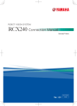
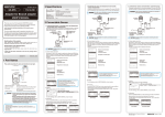
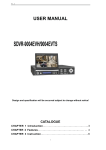
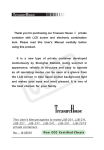
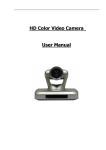
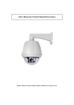
IR DOME PAN TILT USER’S MANUAL Respect for the users: Thank you for our products. This product adopts the company of innovation in the design, PAN-TILT structure optimization, and do a lot of testing on a long time, the adjustment to ensure that the product of the superior quality. All our efforts were in order to make our products more stable performance, and can adapt to the majority of customers' requirements. You can make a better use of equipment, please read this manual, if any problem, please inform us or dealers. Thanks again! Please be sure to selected infrared camera induction Please follow the instructions strictly 1 CONTENTS DC-485R HDD SYSTEM TIANDI DVR PHILIPS SAMSUNG DVR DVR JC-4116 TC-Pelco D HDD SYSTEM HDD SYSTEM RD140(RM110) DVR TC-Pelco P HDD SYSTEM 1、 Feature ……………………………………………………3 10、Specification 2、Attentions …………………………………………………3 MODEL Pan-tilt 3、Use and defend maintenance points for attention…3 IR LED 4、Fundamental structure of pan-tilt……………………5 9、Auto recognition agreements list……………………10 IR LED Input Voltage Pan-tilt Input Voltage Pan-tilt Input Power Can output Voltage Lens driving voltage Angle Speed limit Communication Bus Baud Rate 10、Specification……………………………………………11 Dimension 5、Product external form dimension………………………5 6、Assembly ……………………………………………………6 7、The Built-in Decoder ……………………………………8 8、Bps and address Set …………………………………….. 9 Temperature materials Weight 2 KP-CK63307I KP-CK63309I 7inch 9inch 24 850nm LED, 24 850nm LED, effective distance effective distance 80m 120m DC12V 1.5A 24V AC 50/60Hz 10W DC12V/500mA DC12V/100mA level:0°--355° vertical:0°--90° level:10°/S vertical:5°/S level adjustment RS485 1200/2400/4800/9600 BPS 200×75×70 mm 150×65×70 mm (V×T×H) (V×T×H) -25℃--49℃ CoverFlame-retardant ABS or aluminum optical transparent cover: Acrylic 3.0Kg 3.5Kg 11 30 0011110 40 0101000 50 0110010 60 0111100 31 0011111 41 0101001 51 0110011 … ……… 32 0100000 42 0101010 52 0110100 … ……… 33 0100001 43 0101011 53 0110101 127 1111111 34 0100010 44 0101100 54 0110110 note:1=ON,0=OFF explain:DIP switch to digital is "OFF",The corresponding number is 0,Dial “ON”, The corresponding number is 1。 7 DIP switch is address code switch, adopt binary coding, can setting 128 different address code, 9 is low, 3 is high, encode according from low to high Address calculation method:( Below is the switch “ON” the state of the value in) switch: 3 4 5 6 7 8 9 value: 64 32 16 8 4 2 1 1, select the mann yards agreement, the address code number starting from 0, the maximum set to 128, which corresponds to the matrix decoder addresses the camera 1 to 0; when the system is used in more than 64 decoder should use the code distributor to achieve expansion. 2, Shanghai Chenova system for all agreements and KODICOM system KRE-301 protocol address encoded as 16 hex mode, the system address is "10", the actual address of the corresponding decoder 16. 3, part of the system, PELCO P / HY protocol address is 1, the software is set to 1, corresponding to the address decoder is set to 2. 9、Auto recognition agreements list: agreements name Adaptive System agreements name Adaptive System Pelco D Pelco P DVR DVR ST-832 Pelco D WX HDD SYSTEM HDD SYSTEM CS850 DVR HIKVISION DVR 10 1、Feature Special Designed Camera, IR LED Partition Ray System, Without Glisten Phenomenon. Used the powerful IR LED from Taiwan, Qualified Disperse Heat solution to avoid part warm up. Constant power supply to ensure the IR LED for long time working. IR LED Board has the Windy Circle system; Once the LED on, it works. When long distance watching, the IR field can be adjusted. Powerful power supply, stable electricity and pressure suitable for long time working. Double Anti-sunshine structure, weatherproof for out door/ In door using. Acrylics Optics Housing, No distortion. 2、Attentions: ☆ Don't be installed in the indoor of the equipment exposed to rain or moisture ☆ Don't be put inside the device objects, which could cause a short-circuit and damaged equipment or system; ☆ Avoid installation in flammable and explosive gas or corrosive gas exists; ☆ Don't remove pan-tilt internal components and parts and repair itself; ☆ Don't exceed the environment temperature, humidity standards; ☆ AC24V power supply for pan-tilt, DC12V power supply for infrared lamp, Please confirm by strict specifications, higher than the voltage access the voltage specification access will cause equipment burn。 3 3、Use and defend maintenance points for attention: ☆ In the repair, replacement or cleaning the product, please cut off power supply。 ☆ Supporting power source elicitation line if necessaries lengthen, general the length can not exceed 10 meters , The line footpath can not be lower than 0.5 mm directly 2。 ☆ When cleaning, please do not use this product type or spray liquid cleaner, otherwise it will cause short-circuit internal line。 ⑤JP5:Dial DIP switch to digital is "OFF",The corresponding number is 0,Dial“ON”,The corresponding number is 1。Article 1-2 says bps and special agreement, Article 3-9 says decoder board address. 8、Bps and address Set: 1. Special agreements and communication bps Set(Auto identification of initial state of agreement,2400bps,as000) DIP1-2 BPS agreement note 00 2400 01 4800 10 9600 Auto recognition agreements Auto identification in more than 20 agreement, auto recognition agreements list ☆ Camera equipment installation, please promptly after fixed camera lens video, and power lines, to prevent pan-tilt rotating process and equipment damage cable pan-tilt。 ☆ When installation, please pay attention to protect transparent cover carelessly, such as dirty, with a soft cloth and neuter cleaner cleanness ☆ Installs when the camera and the transparent cover please defer to the arrow to show the direction installment ☆ Installed outside, please support joints and screw in waterproof, prevent water treatment equipment, damage to the equipment into the indoor 4 explain:DIP switch to digital is "OFF",The corresponding number is 0,Dial “ON”, The corresponding number is 1。 2. address Set(The initial ID: 1,as 000001) ID DIP3—9 ID DIP 3—9 ID DIP 3—9 ID DIP 3—9 1 0000001 7 0000111 13 0001101 19 0010011 2 0000010 8 0001000 14 0001110 20 0010100 3 0000011 9 0001001 15 0001111 21 0010101 4 0000100 10 0001010 16 0010000 22 0010110 5 0000101 11 0001011 17 0010001 23 0010111 6 0000110 12 0001100 18 0010010 24 0011000 25 0011001 35 0100011 45 0101101 55 0110111 26 0011010 36 0100100 46 0101110 56 0111000 27 0011011 37 0100101 47 0101111 57 0111001 28 0011100 38 0100110 48 0110000 58 0111010 29 0011101 39 0100111 49 0110001 59 0111011 9 7、The Built-in Decoder: 4、Fundamental structure of pan-tilt: JP3:Decoder board pan-tilt control output pin definition JP4:Camera power supply and lens out pin definition JP1:RS485 and AC24V input JP2:120 Ω 485 termination resistance Jump line JP5:DIP switch ①. JP1:RS485 and AC24V input:1P:485 A+;2P:485 B-;3、4P: 24VAC input。 ②. JP2:120Ω 485 termination resistance Jump line:485 communication in the most distant communication lines between A and B through A 120 Ω load resistance, in order to improve the reliability of communication. ③. JP3:Decoder board pan-tilt control output pin definition: NO Cable color definition NO Cable color definition 1 BLACK COM 4 YELLOW LEFT 2 RED AUTO 5 GREEN DOWN 3 WHITE UP 6 BLUE RIGHT 5、Product external form dimension: ④. JP4:Camera power supply and lens output pin definition: NO definition NO definition NO definition 1 CAM 12V+ 3 LENS(COM) 5 LENS (FOCUS) 2 CAM 12V- 4 LENS(IRIS) 6 LENS (ZOOM) 8 5 6、Assembly: 1.Set up the Bracket, put the cable through the bracket. 2.Connect the Pan-tilt with the bracket, fix the screw to the Ball Housing to make sure waterproof. 3.Connect the Power supply, video, RS 485 and lens controller cable to the Pan-tilt, please refer to the Form 1 and Form 2. 4.Check the IR Middle Speed dome whether works properly, if all is ok, please use the screw to fix the Transparent Cover to the Ball Housing, then installation finished. 5.Pan-tilt Position-limit adjustment pan-tilt Under may adjust position-limit , general horizontal condition by hand movement, the product already has tuned up when leaving the factory horizontal position-limit, the customer adjusts unnecessarily once again。 Initial value: level:0°-355° vertical:0°-90° When needing to carry out adjustment handle as follows: And then silk loosens the horizontal position-limit piece fastening top , move the position-limit piece when till required location, screwing down is equivalent to silk in being OK again。 Figure 2、Iris rvvp 1 2 3 4 gray white purple green zoom focus iris com Figure 3、Camera and IR power cord 1 2 3 4 red black yellow green Cam + Cam - IR + IR - Figure 1、Pan-tilt rvvp NO 1 2 3 4 5 6 Cable color definition red up brown down yellow left green right blue auto black com 6 7