1
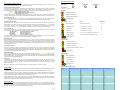
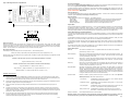
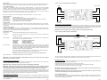
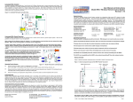
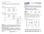
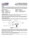
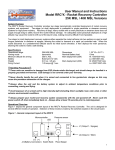
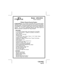
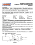
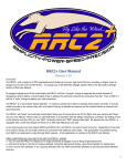
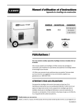
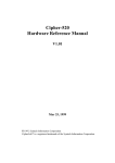
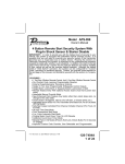
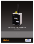
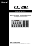
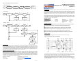
Figure 5 - Menu Navigation and Operation Flowchart
User Manual and Instructions
Model RRC2- mini - Rocket Recovery Controller
Revision 1.2
Invoking the Start Menu
Start
Press & Hold
Select PB
Power-up
altimeter
Wait for
chirp
Start Menu
activated
Release
Select PB
System Overview
The RRC2-mini Rocket Recovery Controller provides two-stage barometrically controlled deployment of rocket
recovery systems and equipment. Two-stage (or dual) deployment is preferable to single parachute or streamer
recovery systems for high-power rocketry. Recovery of large, heavy rockets with a small parachute or streamer
alone does not supply enough drag to safely recover the rocket without damage. An adequately sized parachute
deployed at a high altitude may cause the rocket to drift out of the launch area, making recovery difficult if not
impossible.
Menu Navigation
Start
LED shows
choice
No
Select PB
No
Enter PB
Yes
Two stage (or dual) deployment recovery systems either separate the rocket airframe into two sections or eject a
small drogue parachute or streamer at apogee, allowing the rocket to descend at a rapid yet controlled rate. When
the rocket descends to a predetermined altitude above its initial launch elevation, it then deploys the main parachute, allowing the rocket to make a safe landing.
Yes
Next menu
choice
Take this menu
choice
General Specifications
Operational range
Arming mode
Minimum altitude for arming
Battery/Power range
0-40K MSL
barometric
250 ft. AGL
9V / 7-10V
Dimensions
Nominal Battery load
Output current (sinking)
Continuity current
Weight
1" W x 3.15" L
6-14ma
5A @ 0.5 sec
9µa
17 grams
Modifying a Setpoint
Start
LED shows
setpoint ID
No
Select PB
Yes
Next setpoint
ID
Handling Precautions
Always handle in a properly grounded environment. ESD damage is not covered under your warranty.
No
Enter PB
A
Never touch/handle the unit when it is armed and connected to live pyrotechnic charges.
Yes
Always allow the unit to adjust to ambient temperature conditions prior to arming and flying.
Avoid exposure of an armed unit to direct sunlight, light level changes, heat, cold, or wind.
Chirp/Flash
Setpoint
Always prepare your rocket and recovery system components with the unit powered off.
Never cycle the altimeter power switch off, then immediately back on (allow at least 10 seconds).
No
Select PB
No
Enter PB
Yes
A
Physical Overview
Yes
Figure 1 depicts the general component layout of the RRC2-mini Rocket Recovery Controller.
Figure 1 - General component layout of the RRC2-mini
Tap in new
value with
Select PB
Battery
MCU
Piezo LED
Enter PB
Drogue Output
Select PB
Main Output
Tap Enter
PB when
complete
Product Warranty
Missile Works Corporation has exercised reasonable care in the design and manufacture of this product and warrants the
original purchaser that the RRC²-mini is free of defects and that it will operate at a satisfactory level of performance for a period
of one year from the original date of purchase. If the system fails to operate as specified, then return the unit (or units) within the
warranty period for repair or replacement (at our discretion). The system must be returned by the original purchaser, and be
free of modification or any other physical damage which renders the system inoperable. Upon repair of replacement of the unit,
Missile Works Corporation will return the unit postage-paid to the original purchaser.
Product Disclaimer and Limit of Liability
Because the use and application of this equipment are beyond our control, the purchaser or user agrees to hold harmless
Missile Works Corporation and their agents from any and all claims, demands, actions, debts, liabilities, judgments, costs, and
attorney fees arising out of, claimed on account of, or in any manner predicated upon loss or damage to property of, or injuries
to or the death of any and all persons arising out of the use this equipment. Due to the nature of electronic devices, and the
application and environments for those devices, the possibility of failure can never be totally ruled out. It is the responsibility of
the purchaser or user of this equipment to properly test and simulate the actual conditions under which the device is intended to
be used to ensure the highest degree of reliability and success.
Missile Works Corporation
PO Box 1725
Lyons, CO 80540
Switch
BaroSensor
Profile
Switch
All user input and output connections are made to the compression terminals as shown. These terminals
include: Battery (for an external 9V), Switch (for an external power switch), and Drogue/Main (for external
deployment charges or controls). All terminals are marked on the board silkscreen for reference.
Note: Before using the RRC2-mini, first remove the protective tape covering the Profile Switch. Slide
the Profile Switch to the left, selecting Profile 1. The function of this switch is covered in subsequent
sections of this manual.
Pg. 1
Tel: 303.823.9222 Fax: 303.823.9777
On the World Wide Web @ www.missileworks.com
Copyright 2000-2007 by Missile Works Corporation.
All rights reserved.
Pg. 8
Setpoint and Operations Matrix
Flight and Recovery Modes of Operation
The RRC2-mini has several distinct modes throughout the course of its operation during flight and recovery. These modes of
operation are easily identified by the function of the piezo and the LED.
LED Legend:
SOLID
SLOW FLASH
X
Power-up mode with Battery Indicator
When power is first applied to the unit, it will provide a continuous 3-second chirp to indicate it has been switch on. During this
3-second chirp the LED will flicker in 1 of 3 colors relative to battery voltage. This indicator is a quick means of verifying the
operational voltage of your battery without using a voltmeter. The LED colors and the associated battery voltages are:
GREEN
Battery Voltage 8.5 volts or above
YELLOW
Battery Voltage between 8.5 volts and 7.5 volts
RED
Battery Voltage below 7.5 volts
In addition, the unit has an optional battery voltage “lockout” feature during this mode. When enabled, this lockout feature
activates a continuous alarm tone on the piezo and prevents further operation when the battery voltage is at or below 6.5 volts
Baro initialization mode
After the Power-up mode, the unit goes through a 15-second baro initialization start-up delay. The LED will flash slowly in
YELLOW slowly while in this mode. This delay period allows stabilization and establishes an initial barometric history.
Battery/Setpoint Chirp Mode
The RRC2-mini has (2) optional start-up “chirping” options for an “on-the-pad” sanity check. The first of these options is the
“Battery Voltage” chirp feature. When enabled, the battery voltage is chirped on the piezo (and flashed in YELLOW) in volts and
tenths of a volt. The second option is the “All Setpoints” chirp feature. When enabled, ALL current setpoint values are chirped
on the piezo (and flashed in YELLOW) in setpoint order. If neither of these options are enabled, this mode is skipped.
Launch Detect mode
When all previous modes are complete, the unit transitions into launch detect mode. The piezo and the GREEN LED indicate
the continuity status of the drogue and main output terminals every 2 seconds as follows:
Long Beep/Flash
No continuity on Drogue or Main
1 Short Beep
Continuity on Drogue only
2 Short Beeps
Continuity on Main only
3 Short Beeps
Continuity on Drogue and Main
The unit also monitors the barometric sensor for a change of 250 feet in elevation to determine the launch of the rocket. After
this change, the unit transitions into mach inhibit mode (if enabled) or apogee detection mode.
Mach Inhibit mode
When enabled after launch detection, the LED flashes RED at 1Hz. The unit is actively sampling baro changes, yet it will not
apply the apogee detection algorithm during this delay mode. Mach Inhibit mode is used to prevent the barometric “spoofing”
that occurs during sonic-subsonic transitions during rocket boost. This is a Bernoulli-based effect and is most pronounced at
motor burnout (typically the largest velocity delta of the rocket flight). After the expiration of the mach delay, the unit transitions
into apogee detection mode.
Apogee Detection Mode
When the unit is actively sampling for the apogee event, the LED will be SOLID RED. When the unit determines that apogee
has occurred (by a positive pressure slope), it will initiate the apogee event. The Drogue and Main outputs may activate based
upon the configuration of the Deployment Mode setpoint and the Drogue/Main Delay setpoints. (note: All flight data are written to
nonvolatile memory immediately after the apogee event).
Main Detection Mode
After the unit has detected apogee, it will transition to Main Detection Mode, indicated by a SOLID YELLOW LED. The unit will
continue to sample barometric pressure during the descent phase of the flight until it reaches the designated main deployment
elevation (above ground). The Drogue and Main outputs may activate based upon the configuration of the Deployment Mode
setpoint and the Drogue/Main Delay setpoints.
Report mode
After detection of the main elevation, the unit will report the peak altitude it measured during flight. The piezo and the GREEN
LED will continuously report the peak altitude by chirping out the individual digits of the measurement. Depending on the peak
altitude, the unit will chirp out 3, 4, or 5 digits. For example, let’s say the rocket flew to a peak altitude of 1230 feet. The unit
would beep as follows:
X
FAST FLASH
X
X = LED Color
R = RED / G = GREEN / Y = YELLOW
Start Menu
R
Navigate to Setpoint Menu
G
Navigate to Flight Log Menu
Navigate to Diagnostics Menu
Y
R
Exit to Flight Mode
G
Setpoint Menu
Range
Default value
R
Main AGL Setpoint
3-30 (300’ to 3000’ AGL)
5 / 10
G
Mach Inhibit Delay
1-31 seconds (32 = no delay)
32
Y
Drogue Delay
1-15 seconds (16 = no delay)
16
R
Main Delay
1-15 seconds (16 = no delay)
16
G
Deployment Mode
1-3 / 1 = Dual , 2 = Apogee Only, 3 = Main Only
1
Y
Operations Mode
1-16 / See Operations Mode Setpoint Table
16
R
Exit to Start Menu
G
Flight Log Menu
R
Last Apogee AGL (feet)
G
Last Peak Velocity (feet/sec)
Y
Last Time to Apogee (sec)
R
Total Launch Count (0-255 since last reset)
R
G
Exit to Start Menu
Diagnostic Menu
R
Battery Voltage level
G
Current MSL elevation
Y
Input Test Mode
R
Output Test Mode
R
Exit to Start Menu
G
Beep...pause…Beep, Beep…pause…Beep, Beep, Beep…pause…Beeeeeeeeeeep… short buzz….(repeat)
Operations Mode Setpoint Table
Basic User Mode
The RRC2-mini provides many new and advanced features over the older model RRC2 Classic and RRC2X altimeter products.
These advanced features are truly optional and are not necessary to use the unit for traditional dual deployment purposes.
In Basic Operation Mode, the user selects the main deployment elevation of 500’ or 1000’ by the position of the Profile Select
switch at power-up time. Profile 1 defaults to standard dual deployment operation with a 500’ AGL main event, and Profile 2
defaults to standard dual deployment operation with a 1000’ AGL main event.
With the exception of the power-up battery indicator mode, the RRC2-mini operates identical to the older RRC2 Classic and
RRC2X altimeters. For users that enjoy the simplicity of setup and use, Basic User Mode provides an easy means to maintain
the same style of operation provided by these older altimeter products.
Advanced User Mode
Although the RRC2-mini can be used in the Basic User Mode, described previously , it is much more capable with many new
advanced operational functions and data recording features. These new functions and data are accessed by using the SELECT
and ENTER pushbuttons in conjunction with the LED in a menu-driven user interface. User-programmable setpoints, historical
flight data, and diagnostics are all accessible via this interactive operation.
Pg. 2
Pg. 7
Figure 4– Mounting Dimensions for the RRC2-mini
Accessing the Start Menu
Please refer to the Setpoint and Operations Matrix reference included in this manual when reading and reviewing this section.
Also refer to the Figure 5- Menu Navigation and Operation Flowchart for additional help.
2” hole centers @ 0.125” dia,
To start the interactive operation of the RRC2-mini, press and hold the SELECT pushbutton while applying power to the unit.
Release the pushbutton after you hear a brief chirp from the piezo. You’re now at the Start Menu and displaying the first choice
(SLOW FLASHING RED / Setpoint Menu)
Start Menu Navigation
To scroll to the next available choice in the menu, tap the SELECT pushbutton. To make a choice in this menu, tap the ENTER
pushbutton. (note: a brief chirp acknowledges each button press).
1”
Start Menu Options
All other menus are accessed from the Start Menu. The available options are:
- Setpoint Menu
Provides verification and adjustment for all user setpoints of the RRC2-mini altimeter.
- Flight Log Menu
Retrieve all previous flight information stored in the altimeters nonvolatile memory.
- Diagnostics Menu
Perform the diagnostic features provided by the RRC2-mini altimeter.
- Escape to Flight Mode
Exit the Start Menu and return to normal flight operations mode.
Setpoint Menu
All user adjustable setpoints are available from this menu. You can verify all setpoints, and likewise you can adjust all setpoints.
The RRC2-mini provides 2 independent setpoint “profiles”. A “profile” is a COMPLETE group of setpoints. Access to either
setpoint profile is based upon the position of the Profile Select switch at power-up. This convention for profile selection applies
to both regular flight operations mode and setpoint adjustments. All setpoint values are stored in nonvolatile memory.
3.15”
0.8”
Setpoint Menu Navigation and Setpoint Adjustment
To scroll to the next available setpoint choice in the menu, tap the SELECT pushbutton. To choose a setpoint, tap the ENTER
pushbutton. After a setpoint has been chosen, the piezo and LED will repeatedly flash/chirp the current value of the setpoint (for
verification).
0.4”
Tap the SELECT pushbutton to scroll to the next setpoint in the menu, OR tap the ENTER pushbutton to modify the chosen
setpoint value. If you’ve elected to modify a setpoint, the unit is now awaiting the new setpoint value.
1”
Static Pressure Ports
Equally as important as sealing the electronics bay or payload section is the proper location, sizing, quality, and quantity of static
pressure ports. Always try to locate a static port on the airframe where it is not obstructed by any object that may cause turbulence
upstream of the airflow over the port. Also try to locate the static port as far away as possible from the nose cone or body transition
sections. The rule of thumb is a ¼” diameter hole for every 100 cubic inches of bay volume.
Tap the SELECT pushbutton according to the newly desired value (example: tap the button 10 times for a value of TEN), then
tap ENTER when complete. Alternatively, tapping ENTER without making any new input will reset the setpoint value to its
default value.
The unit will now chirp back the newly entered setpoint value. Tap the SELECT pushbutton to scroll to the next available setpoint or repeat the programming operation by tapping ENTER again.
Setpoint Menu Options
Main AGL
Bay Volume Calculations
The first step to sizing of the static port hole is to compute volume… use the following formula:
Volume (cubic inches) = Bay Radius (inches) x Bay Radius (inches) x Bay Length (inches) x 3.14
Mach Inhibit Delay
Delay time (in seconds) after launch that the unit will not apply the apogee detection algorithm. The
actual delay time is adjustable between 0 and 31 seconds . Note that 0 seconds (no mach inhibit)
is actually represented by a value of 32.
Drogue Delay
Delay time (in seconds) after apogee detection that the unit will delay the activation of the drogue
output event. The actual delay time is adjustable between 0 and 15 seconds . Note that 0 seconds
(no delay) is represented by a value of 16
Main Delay
Delay time (in seconds) after the Main AGL event detection that the unit will delay the activation of
the main output event. The actual delay time is adjustable between 0 and 15 seconds . Note that 0
seconds (no delay) is represented by a value of 16
Deployment Mode
Represents how the Drogue and Main events are initiated. Dual Deploy Mode (1) operates the
RRC2-mini in standard dual-deploy operation (Drouge event at apogee, Main event at Main AGL
setpoint). Mode 2 (Apogee Only) activates both Drogue and Main events at apogee. If no delay is
programmed for Drogue or Main, then both events are activated simultaneously. Mode 3 (Main Only)
activates both Drogue and Main events at the Main AGL setpoint. Again, If no delay is programmed
for Drogue or Main, then both events are activated simultaneously.
Operations Mode
Enables or Disables a specific operation based upon the setpoint value. Refer to the Operations
Mode Setpoint Table for the specific operational values.
With the known volume of the electronics bay or payload section, calculate the required nominal diameter for a single static port with
the appropriate formula:
If volume <= 100 cubic inches, you can use this simple approximation for a vent hole:
Single Port Diameter (inches) = Volume / 400
If volume > 100 cubic inches, use this formula to calculate vent hole diameter(s):
Single Vent Diameter = 2 x SQRT ( Volume / 6397.71 )
Single Vent Area = ( Single Vent Diameter / 2 ) x ( Single Vent Diameter / 2 ) x 3.14
Multi Vent Diameter = 2 x SQRT ( ( Single Vent Area / # of holes ) / 3.14 )
Operating Tips for Success
•
•
•
•
•
AGL elevation for the MAIN event. It is adjustable between 300’ and 3000’ in 100’ increments
(represented by a value of 3 to 30).
Always pre-test your altimeter as COMPLETELY as possible prior to every flight. This includes a test of the inputs, outputs,
and baro system. The baro sensor inlet is located on the component side of the board, and a small piece of flexible poly hose
can be pressed against the sensor face while you draw a vacuum from the other end of the hose.
- Low Freq Chirp
Enable/Disable modulated piezo operations. Use for dual-unit operation
to discern one unit’s chirp from the other.
Always pre-test your batteries before each flight and ensure they have adequate power capacity for the anticipated worst case
flight profile, including unplanned “on-the-pad” waiting time.
- Chirp Battery Voltage
Enable/Disable voltage chirp feedback during power up. Verify “on-pad”
battery voltage audibly.
Always pre-measure your deployment charge initiators. Measure them for a nominal resistance and verify they are not
shorted.
- Chirp All Setpoints
Enable/Disable chirping of all setpoints (except Ops) in matrix order. Use
this as an “on-pad” verification of all programmed operations.
- Battery Alarm Lockout
Enable/Disable the low battery lockout and alarm (6.5 V and below) .
When active, a continuous alarm tone sounds and the unit will not arm.
Anticipate or know when you should use the mach inhibit function. Barometric “spoofing” occurs during the sonic-subsonic
transition during rocket boost. This is a Bernoulli-based effect and is most pronounced at motor burnout (typically the largest
velocity delta of the rocket flight). Set the delay value for a second or two beyond the anticipated motor burn time to ignore the
phenomenon. “When in doubt, lock it out”.
Proper port-sizing creates ideal equilibrium rates. Ensure that your porting is compliant with the recommended port sizing.
Improperly sized porting or other air leaks in the electronics bay can create parasitic pressure effects, seriously impacting
equilibrium rates and adversely affecting reliable recovery.
Pg. 6
Escape to Start Menu
Exit the Setpoint Menu and return to the Start Menu.
NOTE: All setpoints can be initialized to Factory Defaults by pressing both pushbuttons and performing a power-up.
The unit will respond by a quick piezo chirp and LED flash. Release both pushbuttons to complete the reset.
Pg. 3
Flight Log Menu
Data from your last flight are available from this menu. These values are stored after each flight immediately after apogee detection in nonvolatile memory for later recall. The flight data stay persistent until your next flight overwrites them with new data.
Figure 2 - Low-Current Wiring Diagram for the RRC2-mini
(-) Battery (+)
Drogue e-match
Flight Log Menu Navigation
To scroll to the next available log value in the menu, tap the SELECT pushbutton. To choose a log value, tap the ENTER
pushbutton. When chosen, the piezo and LED will flash/chirp the current value, then return back to menu. Tap the SELECT
pushbutton to scroll to the next setpoint in the menu, or tap the ENTER pushbutton again to reflash/rechirp the current value.
(-)
Similar to the report mode after each flight, log values can chirp out in 1 to 5 digits. For example, let’s say the rocket flew to a
peak altitude of 1230 feet. The unit would beep the following for the Last Apogee AGL value:
(+)
Beep...pause…Beep, Beep…pause…Beep, Beep, Beep…pause…Beeeeeeeeeeep… short buzz….(repeat)
(-)
Flight Log Data Items
Last Apogee AGL
Mach Inhibit Time
Last Time to Apogee
Total Launches
Escape to Start Menu
Diagnostics Menu
From this menu, the unit can also be placed into various modes to verify the basic operational integrity of the unit, including battery power, baro, continuity circuits and output controls. One can also ground test e-matches, ejection charges, or recovery
system designs.
Diagnostics Menu Navigation
To scroll to the next available menu choice, tap the SELECT pushbutton. To choose a diagnostic, tap the ENTER pushbutton.
The piezo and LED will flash/chirp based upon the type of diagnostic chosen. Tap the SELECT pushbutton to scroll to the next
diagnostic in the menu (except in the case of input and output test modes).
Diagnostic Menu Options
Battery Voltage
Chirp/Flash the approximate battery voltage in volts and tenths of a volt.
Current MSL
Chirp/Flash the current MSL elevation in feet.
and temperature conditions.
Input Test Mode
This feature allows the user to verify the operation of the continuity input circuits. It operates identical
to launch detect mode. Chriping/Flashing is as follows:
Long Beep/Flash
1 Short Beep
2 Short Beeps
3 Short Beeps
Output Test Mode
(+)
Peak AGL elevation (in feet)
Approximate velocity in feet/sec (fps), rounded to the nearest 10 fps
Time (in seconds) from arming altitude to apogee event detection rounded to the nearest second
Cumulative total launch count (0 to 255) since last reset
Exit the Flight Log Menu and return to the Start Menu
Power Switch
Main e-match
Wiring Diagram—High-Current/Dual-Battery
Figure 3 depicts the recommended high-current/dual-battery wiring convention for the RRC2-mini. When your recovery system
pyro charges do indeed require higher current, or if you want to configure the most robust and reliable configuration, use the dualbattery configuration as shown. Ensure that the negative sides of each battery are connected together to form a single common.
Observe the proper output terminal connections, using the (-) leg of the drogue and main outputs.
IMPORTANT: Never exceed 20VDC for the secondary pyro battery to avoid damaging the RRC2-Mini.
Figure 3 - High-Current Wiring Diagram for the RRC2-mini
Note that this value is subject to ambient pressure
(-) Battery (+)
(-) Pyro Battery (+)
Pyro Switch
Drogue e-match
No continuity on Drogue or Main
Continuity on Drogue only
Continuity on Main only
Continuity on Drogue and Main
(-)
(+)
This feature allows the user to manually activate the Drogue and Main output circuits. When this
diagnostic is selected, the piezo will emit a WARNING TONE for 5 seconds, and the LED will flash
rapidly in RED to alert the user that output test mode has been selected. After the warning tone is
complete, the unit is ARMED. Press the SELECT pushbutton to activate the MAIN output. Press
the ENTER pushbutton to activate the DROGUE output.
(-)
(+)
Main e-match
Note: A useful accessory for testing the outputs are 12-volt DC panel lamps. The lamps will allow you
to observe the operation of the outputs without the use of pyrotechnic devices.
IMPORTANT: Always exercise caution if using live pyro charges in the output test mode.
Escape to Start Menu
Power Switch
Exit the Diagnostics Menu and return to the Start Menu.
IMPORTANT: After selecting the Input/Output Test Mode diagnostic feature, you must power off the unit prior to flight,
additional testing, or usage of the altimeter.
Battery and Power Source Considerations
The RRC2-mini is designed to be operated with a standard 9-volt alkaline battery. Always purchase and use premium alkaline
batteries; 9-volt NiCad, NiMH, LiPo, or other battery types may also be used.
IMPORTANT: Always use a battery system less than 10 Volts to avoid damaging the RRC2-Mini.
IMPORTANT: Always load-test your battery prior to flight to ensure adequate power reserve for reliable operation and
ignition of the ejection charges. Inadequate sizing of an external battery system or high-current demands on the battery
system during event initiation may lead to power and processor brown-out conditions, resulting in recovery failure.
To load-test a 9V battery, you will require a DC multimeter capable of DC amp measurement with a 10-amp capability. A 9-volt
battery can easily source in excess of 5 amps. Briefly connect the meter leads across the battery terminals to measure the DC
current capacity. If the measurement is close to or drops below 2 amps, do not use the battery. Nominal load during operation is
about 6 ma; and during output firing, the unit can draw well over 1 amp with low current e-matches.
Wiring Diagram/Low Current e-matches
Figure 2 depicts the recommended low-current wiring convention for RRC2-mini. This configuration activates the e-matches using
the same battery that powers the microcontroller and baro-sensing system. The success of this configuration relies on the voltage
remaining relatively stable when firing a low-current e-match. If the voltage sags too low, this may result in a brown-out or other
recovery malfunction.
Pg. 4
The unit has silkscreen labeling showing the designation of all the terminals and the associated polarity for each terminal where
applicable. Stranded 20-22 AWG wire is recommended for the battery and power switch terminals.
Mounting Considerations
The payload section or electronics bay used for the RRC2-mini must be a sealed chamber with a static pressure equalization port.
The sealing of the chamber is necessary for several reasons:
Isolates the electronics from the ejection-charge heat, residue, and over-pressure
Isolates the electronics from the aerodynamic pressure and vacuum effects on the rocket airframe during flight
Provides uniform static pressure equilibrium to ambient pressure during flight
IMPORTANT: Inadequate sealing of the electronics bay or exposure of the electronics to ejection charge heat, BP residue, or pressure will cause the RRC2-mini to malfunction.
IMPORTANT: Black powder residue is extremely corrosive to the circuit board and its components. Always clean off any
inadvertent residue immediately to avoid long-term damage to the unit.
Physical Mounting Dimensions
Figure 4 depicts the physical mounting requirements for the RRC2-mini. 4/40 screw hardware is recommended to mount the unit
into the payload section of the rocket or through a rocket airframe. Nylon standoffs or insulated neoprene washers are also recommended for mounting against a hard back plate.
Pg. 5