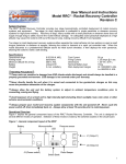
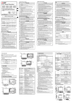
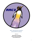
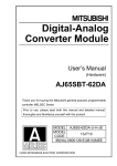
1
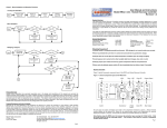
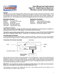
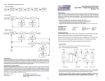
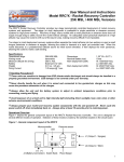
Customized WRC+ Handheld
The WRC+ handheld is also available as a “circuit board only” offering, allowing users to create customized control boxes. This
allows the construction of a custom handheld or launch control console with a users own battery, LED’s, and switch operators.
Each pushbutton or keypad operator is a simple contact closure to ground. Each LED is activated at +3.3V @ 25ma max
current (200 ma total). Figure 10 shows the switch and LED connections for hard wire soldering, or alternatively, the unit can be
ordered with 3.8mm compression terminals.
User Manual and Instructions
Model WRC+ Wireless Remote Control System
Revision 1.10
Figure 10 - Handheld PCB switch and LED wiring
F1 F2 E1 E2 E3 E4 Com
Com 4
3
2
System Overview
The WRC+ Wireless Remote Control System provides four independent high-current FET outputs for hobby
rocketry remote control applications. The most common applications of remote control are redundant recovery
system deployment, staging, air starts, and ground support launch control. The RF communications operate using
a 900MHz spread spectrum transmitter in conjunction with a broadband receiver. The communications also
employ highly secure digitally encoded data packets which provide reliable, interference-free operation of the unit.
This system also obsoletes the need for impounding transmitter units while at an organized launch as each RF
transceiver device operates in a unicast mode to only one other RF transceiver, each with a unique MAC address.
Switches
1
LED’s
Customized WRC+ Rocket Transceiver
The WRC+ Rocket Transceiver can also be packaged into a custom launch control or ground support system. Here are the
guidelines for using the receiver in such an application:
When using the Event Outputs directly for “igniters”, it is critical that the current load does the max rating of the output
MosFET. ONLY use low current igniters or e-matches in this configuration.
General Specifications
Frequency range
RF Output Power
Operational range (200mw)
Operational range (1W)
902-928 MHz
200mw / 1W
up to 4 miles LOS*
up to 20 miles LOS*
Nominal voltage/range
Nominal battery load (9V)
Continuity current (9V)
Output current (sinking)
9V / 7-13.2V
45ma
80µa
5A (slaved)
Handheld Transceiver
Dimensions (LxWxD)
Weight (no battery)
5 ”x 2.75” x 1.25”
130 grams
Rocket Transceiver
Dimensions (LxWxD)
Weight
2" x 4.39" x 0.625”
60 grams
Handling Precautions
Always handle in a properly grounded environment. ESD damage is not covered under your warranty.
Never touch/handle the Rocket Transceiver when it is armed and connected to live pyrotechnic charges.
Always allow the unit to adjust to ambient temperature conditions prior to arming and flying.
If using control relays, solenoids, or other inductive loads on the Event Outputs, the user must ensure that a proper
“flyback” diode is installed to protect the MosFET devices when Event Outputs deactivate. Connect the flyback diode
“cathode” to the (+) side of the Event Output, and connect the “anode” of the flyback diode to the (-) side of the event
output.
The standard WRC+ “or-ties” the continuity input and event output circuits
together. These signals can be segregated when using the device as a
launch controller system by removing the solder jumpers from the Rocket
Transceiver mother board (arrow locations) as shown in Figure 11.
1
2
3
4
Avoid exposure of an armed unit to sudden changes in temperature.
Always prepare your rocket and recovery system components with the unit powered off.
V+
Never cycle the power switch off then immediately back on (allow at least 10 seconds).
Inputs
ALWAYS test compatibility with other onboard avionics when actively transmitting from the WRC+.
ALWAYS test compatibility with the WRC+ when actively transmitting RF from other onboard avionics.
Continuity input signals operate by switching the battery voltage (V+) of the
Rocket transceiver across each associated input. Figure 11 also shows
the hardwire solder connection points for continuity. Alternatively the
unit can be ordered with 3.8mm compression terminals to accept these
input signals.
Physical Overview
Figure 1 depicts the general component layout of the WRC+ Rocket Transceiver board.
Figure 1 - General component layout of the WRC+ Rocket Transceiver
Operating Tips for Success
•
•
•
Figure 11 - Rocket Transceiver continuity inputs
Always pre-test your WRC+ system as COMPLETELY as possible
prior to every flight. This includes a test of the RF system, outputs, inputs, external wiring, antennas, etc.
MMCX Antenna jack
Piezo
Event 3 & 4
Terminals
Battery
Terminals
Always pre-test your batteries before each flight and ensure they have adequate power capacity for the anticipated worst
case flight profile, including unplanned “on-the-pad” waiting time.
Always pre-measure your deployment charge initiators. Ensure they read at a nominal resistance with no short.
Product Warranty
Missile Works Corporation has exercised reasonable care in the design and manufacture of this product and warrants the
original purchaser that the WRC+ system is free of defects and that it will operate at a satisfactory level of performance for a
period of one year from the original date of purchase. If the system fails to operate as specified, then return the unit (or units)
within the warranty period for repair or replacement (at our discretion). The system must be returned by the original purchaser,
and be free of modification or any other physical damage which renders the system inoperable. Upon repair of replacement of
the unit, Missile Works Corporation will return the unit postage-paid to the original purchaser.
Product Disclaimer and Limit of Liability
Because the use and application of this equipment are beyond our control, the purchaser or user agrees to hold harmless
Missile Works Corporation and their agents from any and all claims, demands, actions, debts, liabilities, judgments, costs, and
attorney fees arising out of, claimed on account of, or in any manner predicated upon loss or damage to property of, or injuries
to or the death of any and all persons arising out of the use this equipment. Due to the nature of electronic devices, and the
application and environments for those devices, the possibility of failure can never be totally ruled out. It is the responsibility of
the purchaser or user of this equipment to properly test and simulate the actual conditions under which the device is intended to
be used to ensure the highest degree of reliability and success.
Missile Works Corporation
PO Box 1725
Lyons, CO 80540
Tel: 303.823.9222 Fax: 303.823.9777
On the World Wide Web @ www.missileworks.com
Copyright 2012 by Missile Works Corporation.
All rights reserved.
RX/TX LED’s
RF Module
DIP
Event 1 & 2
Switches Terminals
Power
Cap
All user input and output connections are made to the compression terminals as shown. These terminals
include: Battery (for an external nominal 9V supply) and Events 1 thru 4 (for external deployment charges or
controls). All terminals are marked on the board silkscreen for reference. In addition, a user-furnished 916MHz
antenna is connected via the MMCX connector located on the top of the RF Module.
Note: Before using the WRC+ system, familiarize yourself with the location and designation of all user
connection terminals, DIP switch settings, and the audible and LED feedback functions of the system.
Pg. 8
* LOS = Line of Sight using 3 dBi antenna
Pg. 1
Figure 8 - 916MHz Center Fed Dipole Duck (916MHz center, 1/2 wave, VSWR < 1.9 @ Center Freq, 50 ohm impedance)
WRC+ Operational Terms
Prior to defining the specific operations of the Rocket Transceiver and Handheld Transceiver, its’ necessary to establish some of
the basic terminology used in describing these operations:
Figure 2 - WRC+ Data packet types and packet origination
Handheld Transceiver
1
2
3
4
F1
F2
Command Packet
Query Packet
Ping Packet
Rocket Transceiver
2 to 10
miles
Status Packet
Command Packet
Sent by the Handheld Transceiver to the Rocket Transceiver when any of the Event pushbuttons are pressed.
Query Packet
Sent by the Handheld Transceiver to the Rocket Transceiver to request a Status Packet from the Rocket Transceiver.
Ping Packet
Sent by the Handheld Transceiver to the Rocket Transceiver when in ‘Survey Mode’ to gauge signal strength.
Vertical
Top
Status Packet
Sent by the Rocket Transceiver to the Handheld Transceiver to reflect event continuity status by request, change, or schedule.
Rocket Transceiver Modes of Operation
The Rocket Transceiver board operates in 4 distinct operational modes (selected via DIP switch position) and also provides
additional feedback and status via the piezo and the several LED’s located around the board.
Figure 9 - PCB Blade Antenna (824-960 MHz, -3 dBm, 50 ohm impedance)
Power-up Operations Mode and Battery Level Indicator
When power is first applied, it will chirp the Operations Mode (1 to 4) as set by the DIP switches. Next 2 small packets of data
are exchanged between the main board and RF module (flickering the TX/RX LED’s). If the RF module fails to reply properly,
the piezo will lock on continuously to indicate an RF module fault. If the RF module responds properly, the Operations Mode
chirp is followed by an audible battery voltage level chirp (1 chirp per volt). Anything less than 7 volts will chirp with a continuous
3-second warning tone, indicating a low voltage condition.
IMPORTANT: DO NOT OPERATE THE SYSTEM WITH AN RF MODULE FAULT OR WITH A LOW VOLTAGE CONDITION!
Operations mode
After completion of the battery voltage level chirp, the unit transitions into 1 of its 4 operational modes (selected via DIP switch
position) and also begins the repeated continuity chirp of its 4 events outputs as follows:
No Beeping
1 Short Beep
2 Short Beeps
3 Short Beeps
4 Short Beeps
No continuity on any of the 4 Event outputs
Continuity on 1 of the 4 Event outputs
Continuity on 2 of the 4 Event outputs
Continuity on 4 of the 4 Event outputs
Continuity on all 4 Event outputs
The unit will repeat this continuity chirp function every 3 seconds for as long as power is applied. Anytime an Event Output is
activated from the Handheld Transceiver, the corresponding Event Output LED will also be illuminated on the board. The
following table depicts DIP switch positions vs. the operational mode of the Rocket Transceiver:
Switch 1
OFF
ON
OFF
ON
Switch 2
OFF
OFF
ON
ON
Mode
Receive Only mode (WRC² Legacy mode)
Query Only Transmit Mode
Event Change Transmit Mode
20Hz Transmit Mode
Receive Only mode
This mode operates in a true, “receive only” operation (identical to the original WRC² system) and only processes inbound
Command Packets. It will not allow the Rocket Transceiver to transmit any Status Packets whatsoever (even when a Query
Packet is received). This is the safest mode (when it comes to RF compatibility) as there is no radiated RF from the module.
Query Only Transmit mode
Query Only Transmit mode processes all inbound Command packets and also replies with a Status Packet to all Query Packets
received. This mode is useful for conserving battery power, as Status Packets are sent by Query Packet request only.
Event Change Transmit mode
When operating in this mode, a Status Packet is sent by the Rocket Transceiver for any detected change of continuity status on
the 4 Event outputs. The Rocket Transceiver will also process all inbound Command and Query packets as well. This mode is
particularly useful for conserving battery power, as Status Packets are sent on exception/change only.
20Hz Transmit mode
When this mode is selected, a Status Packet is sent by the Rocket Transceiver every 3 seconds. The Rocket Transceiver will
also process all inbound Command and Query packets as well. This mode is particularly well suited for launch control when
more frequent updates are useful and when battery power from the ground support system is not as large of a concern.
Pg. 2
Pg. 7
Mounting Considerations
Figure 6 depicts the physical mounting requirements for the WRC+ Rocket Transceiver; 4/40 screw hardware is recommended to
mount the unit into the payload section of the rocket or through a rocket airframe. Nylon standoffs or insulated neoprene washers are
also recommended for mounting against a hard back plate.
IMPORTANT: Black powder residue is extremely corrosive to the circuit board and its components. Always clean off any
inadvertent residue immediately to avoid long-term damage to the unit.
Handheld Transceiver Modes of Operation
The Handheld Transceiver operates in 4 distinct operational modes (accessible via programming options) using the 6-button
membrane keypad. It also provides additional feedback and status via an internal piezo and 4 individual LED’s viewable thru the
opaque top panel of the handheld case. The Status LED’s are numbered 1 through4 as shown in Figure 3.
Figure 3 - Handheld Transceiver Top Panel LED and Keypad designation
RPSMA
antenna
jack
Figure 6– Mounting Dimensions for the WRC+ Rocket Transceiver
Status
LED’s
1 2 3 4
Top View
4.39”
2.0”
1.7””
Activate/Deactivate Event 1 Output
Activate/Deactivate the Event 2 Output
Activate/Deactivate Event 3 Output
Activate/Deactivate the Event 4 Output
Query / Ping / Program Ops / Survey Mode
4.09”
Survey Mode / Program Redundancy
0.125” Dia (typ)
Side View
0.625”
Antenna Considerations
The choice of antennas is driven by many factors, so there’s no single antenna that will provide an effective answer to the question of
which antenna type to use. Available space, internal mounting vs. external mounting, airframe materials, along with the attitude and
trajectory of the rocket vehicle when the planned events will most likely occur will all play a role in driving the best choice of antennas
for your project.
The WRC+ RF modules operate between 902-928 MHz with a 915 MHz center frequency. The antenna connector requirements for
each device is as follows:
Rocket Transceiver
Handheld Transceiver
MMCX female socket, requiring an MMCX male connector.
RPSMA female socket, requiring an RPSMA male connector.
Power-up mode (Modes 1 thru 4)
When power is first applied to the handheld (by inserting a 9V battery into the battery compartment after removing the rear
battery door), 2 small packets of data are exchanged between the main board and RF module (flickering the TX/RX LED’s). If
the RF module fails to reply properly, the piezo will lock on and all 4 LED’s will flash continuously to indicate an RF module fault.
If the RF module responds properly you’ll here an audible battery voltage level chirp (1 chirp per volt). Anything less than 7 volts
chirps a continuous 3 second warning tone, indicating a low-voltage condition. In addition, the currently programmed Operation
Mode (1 through 4) is displayed on the Status LED’s as follows during this voltage chirp operation.
IMPORTANT: DO NOT OPERATE THE SYSTEM WITH AN RF MODULE FAULT OR WITH A LOW VOLTAGE CONDITION!
Mode 1—Transmit Only Mode
This mode operates in a true, “transmit only” operation (identical to the original WRC² system) and only processes for outbound
Command Packets. A new Command Packet is sent to the Rocket Transceiver for each and every event key transition on the
handheld keypad. No Query packets are sent in this mode, and no Status Packets are processed from the Rocket Transceiver.
Once an Event Key is initially pressed, the corresponding LED will illuminate to serve as an indicator that a key press was
detected. Also note that Mode 1 is the factory default operation of the Handheld.
The following figures represent the relative performance of the 3 available antenna systems available from Missile Works:
Figure 7 - 916MHz Radome (916MHz center, 1/2 wave, VSWR < 1.9 @ Center Freq, 50 ohm impedance)
Mode 2—Receive Only Mode
Receive Only Mode is a completely passive “receive only” operation and is intended to be used with modes 3 or 4 of the Rocket
Transceiver. Each LED will illuminate when its corresponding event on the Rocket Transceiver has a valid continuity status.
This operation can be used to monitor up to 4 discrete signals within the rocket during flight operations. No Command Packets
and no Query packets are sent in this mode.
Mode 3—Basic Transceiver Mode
This mode combines the operations of both Mode 1 and 2 by sending outbound Command Packets to the Rocket Transceiver
for each event key transition on the handheld keypad, and by illuminating each corresponding LED which represents valid
continuity status with each Status Packet update from the Rocket Transceiver. Users can also send a Query Packet in this
mode to the Rocket Transceiver by pressing the F1 key to manually request a Status Packet Update.
Vertical
Top
Side
Pg. 6
Mode 4—Advanced Transceiver Mode
Advanced Transceiver mode works like Mode 3 but adds additional overhead information to the transport layer to verify and
acknowledge that each outbound packet transaction from the Handheld Transceiver is received and processed by the Rocket
Transceiver. The normal operation of Mode 4 is such that whenever an outbound packet is sent (Command or Query), the
successful acknowledgement and processing of that packet results in nothing. If an outbound packet fails the verification and
acknowledgement process, the result is both an audible 4-chirp alarm tone and a flickering of all 4 LED’s 4 times (restoring.
LED status when complete). This means a packet (or multiple packets) failed to be received and processed. It’s important to
realize that a Query or Command Packet failure sent on an Event key release is much less consequential than a Command
Packet failure on a key press. If this alarm occurs, you can retry the last operation you attempted to perform.
Pg. 3
Note: Each time the Handheld Transceiver receives and processes a Status Packet from the Rocket Transceiver, it will produce a
single “heartbeat” piezo chirp to indicate a successful update.
Note: Always ensure a full 9V battery voltage level when powering up the Handheld Transceiver to ensure maximum system
efficiency and reliability.
Note: Booting up the Handheld Transceiver while the Rocket Transceiver is actively transmitting Status Packets may interfere
with its boot up operation and create an RF Module Fault. Boot up the Handheld Transceiver first to avoid this potential conflict.
Battery and Power Source Considerations (continued)
The Rocket Transceiver battery or power source is subject to the same requirements and scrutiny of the Handheld Transceiver (RF
module power, operational mode, application and use). In addition, it must also be sized to handle the demands of the load(s) on
the Event Output(s). If using low current e-matches, this is a much smaller concern than the control of higher current loads. The
Rocket Transceiver can be used with a single 9V battery if running the device in the “Receive Only Mode”, however if actively
transmitting, one should consider the use of alternative battery sources.
Handheld Transceiver Boot Up Modes of Operation
The Handheld Transceiver can be booted up to operate in 3 additional configuration modes by first pressing and holding the F1
key and/or F2 keys, inserting the battery into the battery holder, then releasing the key(s). Each of these boot-up operations is
unique and described below:
The following table shows the typical power consumption of the WRC+ using the 2 available RF modules:
F1 Key Boot Up / Programming the Operations Mode
When the handheld is successfully booted up with the F1 Key held down, you’ll hear a single chirp from the piezo. All the LED’s
will be off until you release the F1 key. Thereafter, the currently programmed operational mode (1 thru 4) is displayed on the
Status LED’s. To select the new mode of operation, press the Event Keys as follows:
KEY
Event 1
Event 2
Event 3
Event 4
OPERATIONS MODE
Operations Mode 1 / Transmit Only Mode (default)
Operations Mode 2 / Receive Only Mode
Operations Mode 3 / Basic Transceiver Mode
Operations Mode 4 / Advanced Transceiver Mode
As long as you continue to press Event Keys during this programming operation, the Operations Mode and LED display will
continue to change, too. Once you have selected the Operations Mode you desire, press the F1 Key again to exit programming
and save the new Operations Mode in the non-volatile EEPROM memory. The Handheld transceiver will now start in its normal
Power Up Mode (as described on Page 3).
F2 Key Boot Up / Programming the Packet Redundancy Factor
When the handheld is successfully booted up with the F2 Key held down, you’ll hear two chirps from the piezo. All the LED’s will
be off until you release the F2 key. Thereafter, the currently programmed Packet Redundancy Factor (1 thru 4) is displayed on
the Status LED’s. To select a new Packet Redundancy Factor, press the Event Keys as follows:
Duty Cycle (TX = Transmit/RX = Receive)
200 mw Transceiver
1 watt Transceiver
10% TX
55ma
145ma
50% TX
75ma
665 ma
100% TX
120ma
1315ma
100% RX
45ma
45ma
IMPORTANT: Always use a battery system less than 13.2 Volts to avoid damaging the WRC+ Rocket Transceiver.
IMPORTANT: Always load-test your battery prior to flight to ensure adequate power reserve for reliable operation and
ignition of the ejection charges. Inadequate sizing of the battery system or high-current demands on the battery system
during event initiation may lead to low power and processor brown-out conditions, resulting in event failure.
Wiring Diagram/Low Current e-matches
Figure 4 depicts the recommended low-current wiring convention for WRC+ Rocket Transceiver. This configuration activates the
e-matches using the same battery that powers the microcontroller logic and the RF system. The success of this configuration
relies on the voltage remaining relatively stable when activating a low-current e-match. If the voltage sags too low, this may result
in a brown-out or other event malfunction.
Figure 4 - Low-Current Wiring Diagram for the WRC+ Rocket Transceiver
KEY
Event 1
Event 2
Event 3
Event 4
PACKET REDUNDANCY FACTOR
Factor Value 1 / Send 4 packets per command
Factor Value 2 / Send 8 packets per command (default)
Factor Value 3 / Send 16 packets per command
Factor Value 4 / Send 32 packets per command
RF/Logic battery
As long as you continue to press Event Keys during this programming operation, the Packet Redundancy Factor and LED display
will continue to change, too. Once you have selected the Packet Redundancy Factor you desire, press the F2 Key again to exit
programming and save the new Packet Redundancy Factor in the non-volatile EEPROM memory. The Handheld transceiver will
now start in its normal Power Up Mode (as described on Page 3).
To Antenna
(-)
(+)
Power Switch
The Packet Redundancy Factor controls how many Command Packets are sent by the Handheld Transceiver for each Event Key
transition on the membrane keypad. The higher the number of Command Packets sent means there’s a higher probability that the
Rocket Transceiver will be able to receive at least one of those Command Packets. The Handheld Transceiver operates using a
FHSS (Frequency Hopping Spread Spectrum) technique, so additional Command Packets being broadcast will cover a larger
spectrum of frequencies. In addition, the Handheld Transceiver applies a random time delay between each Command Packet,
thus staggering the time domain should there be any other RF traffic in this 902-928 MHz ISM band. The downside(s) to using a
higher Packet Redundancy Factor is the additional time required to send all the queued up Command Packets and a higher
probability for un-acknowledged packets if using the Advanced Transceiver Mode, creating false alarm conditions.
Event e-match (typical)
F1/F2 Key Boot Up / Invoking the Survey Mode
When the handheld is successfully booted up with both the F1 and the F2 Key held down, you’ll hear three chirps from the piezo.
In addition, the LED’s will ramp on from left to right until all 4 LED’s are illuminated. They will remain on until you release both the
F1 key the F2 key. Once both keys are released, the Handheld transceiver will chirp the battery voltage (as described on Page 3),
but instead will be operating in a special Survey Mode.
Wiring Diagram—High-Current/Dual-Battery
Figure 5 depicts the recommended high-current/dual-battery wiring convention for the WRC+ Rocket Transceiver. When your
output events do indeed require higher current, or if you want to configure the most robust and reliable configuration, use the dualbattery configuration as shown. Ensure that the negative sides of each battery are connected together to form a single common.
Observe the proper output terminal connections, using the (-) leg of the Event outputs.
The Survey Mode feature provides a means to gauge the overall efficiency and actual signal strength of the data packets received
by the Rocket Transceiver Unit. This is done by sending a Ping Command (via the F1 Key). Whenever a Ping Command is sent
by the Handheld Transceiver, the Rocket Transceiver will reply back with the relative signal strength of that packet. This signal
strength is displayed as a level from 1 to 4 on the Status LED’s and chirped on the piezo 1 to 4 times. If no reply was received
from the Rocket Transceiver, the LED’s will be off and there will be no tone from the piezo (or the previous LED level will remain).
IMPORTANT: Never exceed 20VDC for the secondary pyro battery to avoid damaging the WRC+ Rocket Transceiver.
LED Level
1
2
3
4
RF Signal Levels
-90 dBm or less
-70 dBm to -89 dBm
-50 dBm to -69 dBm
-49 dBm or higher
Figure 5 - High-Current Wiring Diagram for the WRC+ Rocket Transceiver
RF/Logic battery
To Antenna
(-)
The higher the LED signal level, the stronger the RF signal. All Event keys and Command Packet operations are disabled in
Survey Mode, and Survey Mode operations will continue until the Handheld Transceiver is powered off. Also note that sending a
Ping Command deactivates all outputs on the Rocket Transceiver should any of them be latched on due to poor or intermittent
RF communications. All Status Packets from the Rocket Transceiver are ignored while operating n Survey Mode.
Battery and Power Source Considerations
The WRC+ system is available with 2 different RF module systems (200mw and 1W), and it can be run in several different modes
of operation with various applications of those operational modes, so your battery or power source solution is very dependent on
what your mission profile requires. The Handheld Transceiver was designed to use a standard 9-volt alkaline battery; however
extensive Event Key activation using a 1 watt RF Module will put quite a demand on your battery, whereas the use of a 200mw
device is significantly less demanding. Always purchase and use premium alkaline batteries for your Handheld Transceiver; 9-volt
NiCad, NiMH, LiPo, or other battery types may also be used.
Pg. 4
(+)
Power Switch
Pyro battery
(-)
(+)
Event e-match (typical)
Pyro Switch
The unit has silkscreen labeling showing the designation of all the terminals and the associated polarity for each terminal where
applicable. Stranded 20-22 AWG wire is recommended for the battery and output event terminals.
Pg. 5