1
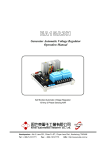
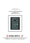
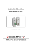
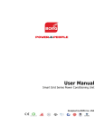
ACU230
Twin Power Air Operation Manual
Headquarters : No.3, Lane 201, Chien Fu ST., Chyan Jenn Dist., Kaohsiung, TAIWAN
Tel : + 886-7-8121771
Fax : + 886-7-8121775
URL : http://www.kutai.com.tw
1. INTRODUCTION
3. THE ACU230 MODULE
The TWIN AC Control is a device to control two Air
Conditioners on a Cell-Phone Repeater Station. The
ACU230 control automatically transfers from one
AC to the other at pre determined times or turns the
both units in ON when high indoor temperatures
demands it. It constantly monitors the power
sources for over and under voltage, over and under
current. The control unit also provides dry
contactors for each failure and AC ON/OFF status
lights making it possible to monitor it remotely. In
addition a fully illuminated front panel immediately
reports to the operator the condition of the system.
If the ACU230 control unit fails, it has two breakers
for manual override, these breakers forces any of
the AC ON/OFF.
The user can remotely operate both AC from the
control center away from station.
The pc-board is protected with epoxy.
2. FEATURES
DISPLAY :
● Power input 220VAC 50/60HZ ±15%.
● Magnetic contact switch capacity:
Ith=32A. (Other sizes available)
maximal
KEY : Function select bottom. This bottom can
selects which parameter you need to
change. ( OV, UV, OC, OT, UT …etc )
KEY : Increase value.
▼
KEY : Decrease value.
F
● Over and under voltage protection.
● Over and under current protection.
● Real time room
7-segment LED.
temperature
display
by
● Real time voltage and current display.
R KEY : Reset bottom. this key erases all setting
and the control unit returns to preset
program.
● Emergency manual override.
● Remote start.
● Easy to adjust protective functions using the front
panel controls.
A 4 characters digital monitor indicates
temperature or current setting and helps in
the programming procedure.
T
KEY : Lamp test bottom.
P
KEY: The ACU230 control power switch.
● Clear status indicators: Power on, under
temperature, over temperature, under voltage,
over voltage, under current, over current, Acu1
on, Acu2 on.
● Dry contacts for remote failure supervise, easy to
adopt to any monitoring.
● A single-chip microprocessor is utilized, that
make hardware more reliability.
● A removable digital temperature sensor is easy to
install anywhere inside the room.
● Temperature error value less than ± 0.5 °C.
● Programmed memory settings are never loss.
● Dimension: 220 (W) * 380 (H) * 140 (D) mm.
______________________________________________________________________________________
2
ACU230
4. FUNCTION SETTING AND
ADJUSTMENT
4.1 OVER TEMPERATURE SETTING
4.1.1 GENERAL ESCRIPTION
When the temperature is higher than the over
temperature setting, the over temperature LED
lights up and the ACU230 module provide a dry
contactor for an external alarm signal.
The setting range for over temperature is 25°C ~
40°C and the preset value is 31°C.
4.1.2 ADJUSTMENT
1. Press F key and select “FUN1”.
2. Press or key until the new value you want
to set.
3. Waiting for 5 sec let the microprocessor read the
new value and change its internal settings.
4. The monitor returns to current temperature
display and finish this over temperature setting.
4.2 WORING TEMPERATURE SETTING
4.2.1 GENERAL DESCRIPTION
The working temperature is defined as the best
temperature for the room. If the current temperature
is over the working temperature setting, the ACU230
control unit starts one of the air-compressors, later
the ACU230 shut down the working AC when the
temperature reaches 1°C under the working
temperature setting.
4.3 TEMPERATURE
SETTING
FOR
THE
STANDBY AC
4.3.1 GENERAL DESCRIPTION
If the temperature does not decrease with just one
AC, and if the temperature is still high, the standby
AC starts and runs together with the main AC.
For example, if the working temperature setting is
25°C and temperature setting for the standby AC is
2°C higher when the room temperature goes over
25°C, only one of the AC runs. But if the temperature
goes over 27°C, The controller starts both AC
running them together.
When the temperature decrease under 26°C, the
ACU230 module will shut down the standby AC..
The setting range of the standby AC temperature is
from 1°C ~ 10°C, and the preset setting is 2°C.
4.3.2 ADJUSTMENT
1. Press F key and select “FUN3”.
2. Pre Press or key until the new value you
want to set.
3. W Waiting for 5 sec let the microprocessor read
the new value and change its internal settings.
4. The monitor returns to the current temperature
display and finish the temperature setting for the
standby AC.
4.4 UNDER TEMPERATURE SETTING
4.4.1 GENERAL DESCRIPTION
(The internal setting 1°C is unalterable.) The setting
range of working temperature is from 20°C ~ 30°C,
and the preset setting is 27°C.
When indoor temperature is lower than the under
temperature setting, the under temperature LED
Illuminates and the ACU230 module provide an
independent dry contactor for remote alarm.
4.2.2 ADJUSTMENT
The setting range of under temperature is from 10°C
~ 25°C, and the preset value is 20°C.
1. Press F key and select “FUN2”.
2. Press or key until the new value you want
to set.
3. Waiting for 5 sec let the microprocessor read the
new value and change its internal settings.
4. The monitor returns to current temperature
display and finish this new working temperature
setting.
______________________________________________________________________________________
ACU230
3
4.4.2 ADJUSTMENT
4.6.2 ADJUSTMENT
1. Press F key and select “FUN4”.
1. Press F key and select “FUN6”.
2. Press or key until the new value you want
to set.
2. Press or key until the new value you want
to set.
3. Wait Waiting for 5 sec let the microprocessor
read the new value and change its internal
settings.
3. Waiting for 5 sec let the microprocessor read the
new value and change its internal settings.
4. The monitor returns to current temperature
display and finish the under temperature setting.
4. The monitor returns to current temperature
display and finish the under voltage setting.
4.7 OVER LOAD CURRENT SETTING
4.5 OVER VOLTAGE SETTING
4.5.1 GENERAL DESCRIPTION
The ACU230 control unit can monitor the input AC
power quality. When alternating voltage is over the
over-voltage setting, the over voltage LED lights up
and the ACU230 module provide an independent dry
contactor for the alarm signal. When over voltage
failure occur the ACU230 will shut down working AC
and start the standby AC to continue work until the
voltage return to normal.
The setting range of over voltage is from 230VAC ~
275VAC, and the preset value is 250VAC.
4.5.2 ADJUSTMENT
1. Press F key and select “FUN5”.
2. Press or key until the new value you want
to set.
3. Waiting for 5 sec let the microprocessor read the
new value and change its internal settings.
4. The monitor returns to current temperature
display and finish the over voltage setting.
4.7.1 GENERAL DESCRIPTION
The over current protect function avoids any damage
to your system when external over load or short
circuit occurs.
If the ACU230 control unit detects over current on the
line the control module shuts down the working AC
and start the standby AC to maintain cooling.
The over current LED is illuminated and the ACU230
module provide an independent dry contactor for the
external alarm signal. This error message will not be
erased until user presses the P key to shut down and
restart the ACU230 module. The operation current
must be different for different air-compressor, so
please refer to air-compressor’s user guide before
you set the over current.
The setting range for over current is from 5A ~ 50A,
and the preset value is 20A over-current.
NOTE :
CHECK IF THE EXTERNAL POWER AND THE
LOAD IS NORMAL BEFORE YOU RESTART THE
ACU230 CONTROL UNIT.
4.6 UNDER VOLTAGE SETTING
4.6.1 GENERAL DESCRIPTION
4.7.2 ADJUSTMENT
The ACU230 control unit can monitor the input AC
power quality.
1. Press F key and select “FUN7”.
When alternating voltage is under the under-voltage
setting, the under voltage LED lights up and the
ACU230 module provide an independent dry
contactor for the external alarm signal. When under
voltage failure occur the ACU230 will shut down
working AC and start the standby AC to continue
work until the voltage return to normal.
2. Press or key until the new value you want
to set.
3. Waiting for 5 sec let the microprocessor read the
new value and change its internal settings.
4. The monitor returns to current temperature
display and records the new over load current
setting.
The setting of under voltage is from 210VAC ~
165VAC, and the preset value is 180VAC.
______________________________________________________________________________________
4
ACU230
4.8 DER ACTION CURRENT SETTING
4.8.1 GENERAL DESCRIPTION
The ACU230 control continually monitors the load
current for each AC when they are running. If the
current is lower than the under current setting, the
control unit judges this air-compressor is defective
shutting down this unit and start the other AC to
continue cooling. Subsequently the under current
LED lights up and the ACU230 module activates an
independent dry contactor to activate and external
alarm signal. This error message cannot be erased
until the user presses the P button to reset the
module.
The setting range for under current is from 0A ~ 10A,
and the preset value is 0.0A.
NOTE :
IF UNDER CURRENT TRIPS, YOU MUST RESET
THE ACU230 CONTROLLER BY PRESS THE
POWER KEY.
4. The monitor returns to current temperature
display and finish the change over time setting.
4.10 REAL-TIME VOLTAGE AND CURRENT
DISPLAY
The ACU230 control unit provided user could read
real-time voltage and current from front display
without any meter. It is very useful to help user
understand and monitor the air-compressors working
condition.
To read the data off the ACU1, press the “F” key until
the display shows “Acu1”. Then display shows ACU1
real-time voltage & current about 12 sec and
automatically return to normal status.
To read the real-time data from the ACU2, press the
“F” key until display shows “Acu2” The display will
show ACU2 real-time voltage & current about 12 sec
and then automatically return to normal status.
4.8.2 ADJUSTMENT
1. Press F key and select “FUN8”.
2. Press or key until the new value you want
to set.
3. Waiting for about 5 sec then the microprocessor
will read current value and change the internal
setting.
4. The monitor returns to current temperature
display and finish the under action current
setting.
4.9 CHANGE OVER TIME SETTING
4.9.1 GENERAL DESCRIPTION
The ACU230 control unit automatically transfers the
working air-compressor to standby air-compressor
after change over time. This function will make these
two air-compressors have same working hours.
The setting range of change over time is 1hour ~
168hours, and the outgoing setting value is 24 hours.
4.9.2 ADJUSTMENT
1. Press F key and select “FUN9”.
2. Press or key until the new value you want
to set.
3. Waiting for 5 sec let the microprocessor read the
new value and change its internal settings.
______________________________________________________________________________________
ACU230
5
5. WIRING AND TERMINAL BLOCK
NOTE :
THE TERMINAL POSITION PLEASE REFER THE
DIAGRAM BELOW.
1. Terminal 1: The ACU2 Magnetic contact switch
control terminals.
2. Terminal 2: The ACU1 Magnetic contact switch
control terminals.
3. Terminal 3&4: The ACU2 current transformer
signal input terminals.
4. Terminal 5&6: The ACU1 current transformer
signal input terminals.
5. Terminal 7&8: The ACU1 alternating power
source input terminals.
6. Terminal 9&10: The ACU2 alternating power
source input terminals.
7. Terminal 11~13: The ACU1 and ACU2 remote
start signal input terminals.
When terminal 12 and 13 close, then the ACU1
start.
When terminal 12 and 11 close, then the ACU2
start.
8. Terminal 14~16: The ACU2 on auxiliary free
contactors terminals.
9. Terminal 17~19: The ACU1 on auxiliary free
contactors terminals.
10. Terminal 20~22: The over current
auxiliary free contactors terminals.
alarm
11. Terminal 23~25: The under current alarm
auxiliary free contactors terminals.
12. Terminal 26~28: The over voltage
auxiliary free contactors terminals.
alarm
13. Terminal 29~31: The under voltage alarm
auxiliary free contactors terminals.
14. Terminal 32~34: The over temperature alarm
auxiliary free contactors terminals.
15. Terminal 35~37: The under temperature alarm
auxiliary free contactors terminals.
16. SW1 : The manual force ACU1 start switch.
17. SW2 : The manual force ACU2 start switch.
18. CN1: The temperature sensor connects housing.
19. Fuse 1: The ACU1 input power protect fuse.
20. Fuse 2: The ACU2 input power protect fuse.
______________________________________________________________________________________
6
ACU230
6. TWIN POWER AIR ATS CONNECT WIRE DIAGRAM
______________________________________________________________________________________
ACU230
7
7. EXEMPLIFICATION OF INSTALLATION
______________________________________________________________________________________
8
ACU230