1
1 Introduction and Overview
1.1 COMPASS readout
)
(Fibre
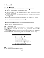
The CATCH-X (CATCH = COMPASS Accumulate, Transfer and Control Hardware), a multipurpose frontend-electronic driver and readout module, has been developed in the scope of
the COMPASS experiment located at CERN. This state-of-the-art xed target spectrometer is
capable of standing beam intensities of up to 2 108 particles/spill. At a maximum trigger rate
of 105 events/s several Gigabyte of data has to be read every second with negligible dead time.
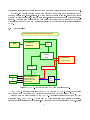
The readout architecture of the
LAT
Calorimeter
RICH
SAT
COMPASS experiment is summaAPV 6
ASD8b
QVC
GASSIPLEX
rized in Figure 1. Data are digiF1 TDC
DSP
tized right at the detector by the
front-end electronics wherever pos1
16
FE-boards
sible. In case of analog readout the
(detector mounted)
...
pedestal subtraction and zero supmax. 40 MB/s/link
pression is performed by the front(CAT 5+)
(~ 20 m)
end at the detector. To suppress
(Trigger, Clock, event id)
TCS
background for time measurements
(Fibre)
CATCH
only those hits are transfered to the
(9U VME)
(Setup data)
VMEbus
data recording units which have a
(~ 150 m)
correlation to a trigger time.
S-Link
The data are transmitted from
max. 100 MB/s/link
the front-end to the CATCH modules through twisted pair cables or
optical bres. The FPGA based
...
...
...
...
ROB
VME module serves as an interface
between the front-end of the detector systems and an optical S-LINK,
GigaBit
which transmits the data to the
100 MB/s/link
Central
Readout Buer (ROB). It also acts
(Fibre)
Data
GigaBit Switch
as an fan-out for the COMPASS trigRecording
ger distribution and time synchroni(~ 5 km)
sation system (TCS). The readoutdriver monitors the trigger and data
Filter
Filter
Filter
Filter
ow to and from the front-ends. In
addition a specic data buer structure and sophisticated data ow con- Figure 1: The architecture of the COMPASS detector
trol is used to pursue local pre-event readout.
building. At startup the module controls all necessary front-end initialisations.
From the CATCH data are transmitted via a standardized link to the read-out buers
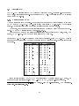
(ROB) which can store all data from at least one spill. The backbone of this data transfer is
the S-link 1] interface and the S-LINK data transfer protocol. Presently about 128 S-LINK
C
P
U
3
G
i
g
a
B
i
t
R
O
B
C
P
U
G
i
g
a
B
i
t
R
O
B
C
P
U
G
i
g
a
B
i
t
R
O
B
C
P
U
G
i
g
a
B
i
t
R
O
B