1
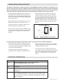
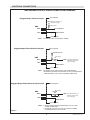
ELECTRICAL CONNECTIONS
RBE ENGAGED OUTPUT SIGNAL CONNECTION DIAGRAMS
User Supplied
Engaged Output Tied to PLC Input
VD C (See Specifications for
maximum voltage.)
R (See Note.)
RBE
Black
To PLC Input
Blue
VD C Common
User Supplied
NOTE:
The minimum value of resistor (R) is 10 x VDC.
User Supplied
Engaged Output Tied to External Indicator
External Indicator
(See Note)
RBE
R
Black
VD C (See Specifications for
maximum voltage and
current ratings.)
Blue
VD C Common
User Supplied
NOTE:
The minimum value of Resistor (R) is equal to VDC divided by
the maximum current limit of the indicator. Be sure current requirement
of External Indicator does not exceed capability of RBE output.
User Supplied
Engaged Output Tied to External Inductive Coil
(See Notes)
External
Coil
RBE
Black
VD C (See Specifications for
1N00
Blue
maximum voltage and
current ratings.)
VD C Common
User Supplied
Figure 3
NOTES: 1. Be sure current requirement of External Coil does not exceed
capability of RBE output.
. Any inductive load, such as a relay coil, must have a 1N00,
or equivalent, diode across it as shown.
FORM NO. 21254-A-0307