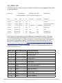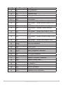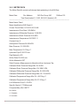
1
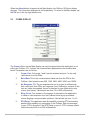
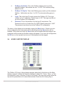
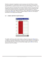
SPARTAN CONTROLS
We Serve the Customer First
Spartan Pocket FloBoss
User’s Manual
www.spartancontrols.com
Document Version 2.0
December 2009
Calgary
403-207-0700
Edmonton
780-468-5463
305 - 27 St SE
8403 - 51 Av
Fort McMurray
780-790-0440
300B MacKenzie Blvd
Grande Prairie
780-539-1161
Regina
306-721-6925
Saskatoon
306-934-3484
Fort St John
250-785-0285
Surrey
604-539-7250
11419 - 98 Av
475 Maxwell Cres
206B-2750 Faithful Av
9603 -112 St
104-19329 Enterprise Way
Spartan Pocket FloBoss - User’s Manual
For additional information on this manual, Pocket FloBoss, or Spartan Controls Ltd,
please contact:
Address:
Spartan Controls Ltd.
305 – 27 Street. S.E.
Calgary, Alberta, Canada
T2A 7V2
General Inquiries:
In Calgary, phone:
(403) 207-0700
Support (24h a day/7 days a week):
Phone:
(403) 207-0700
Web:
http://www.spartancontrols.com
E-Mail:
[email protected]
CONFIDENTIAL
All rights reserved. No part of this document may be reproduced, stored in a retrieval
system, translated, or transmitted in any form or by any means, electronic, mechanical,
photocopying, recording, or otherwise, without prior written permission of Spartan
Controls Ltd.
© Copyright 2009
Spartan Controls Ltd.
We serve the customer first
TABLE OF CONTENTS
Preface
4
1.
Installation of Pocket FloBoss Application
4
1.1.
Download Pocket FloBoss Application
4
1.2
Install Pocket FloBoss
4
1.3
Executing Pocket FloBoss
5
1.4
Running Pocket FloBoss on a Pocket PC 2003
5
2.
3.
Operation - Operator Displays
5
2.1
Main Display
6
2.2
About Display
6
2.3
Comm. Display
7
2.4
Hourly History Display
8
2.5
Hourly History Chart Display
9
2.6
Daily History Display
10
2.7
Daily History Chart Display
11
2.8
AGA Display
11
2.9
Report Display
12
2.9.1
Alarm Log
13
2.9.2
Event Log
14
2.9.3
Meter Data
16
Appendix A - Troubleshooting
We serve the customer first
17
PREFACE
Pocket FloBoss is a Windows CE application written to interface a PocketPC 2002
with the Fisher FloBoss 103. It does this using a RS-232 serial port of a PDA (Personal
Digital Assistant) to communicate with the FloBoss using ROC protocol. The FloBoss
103 calculates Gas Flow for one flow run. Pocket FloBoss is programmed to retrieve
current operating parameters, modify operating parameters, view and chart hourly
history data from the past 35 days, view, chart and save daily history data for the past
35 days, save alarm log, save event log, and save meter data for the single flow run. All
data displayed is assumed to be in metric units.
1.
INSTALLATION OF POCKET FLOBOSS APPLICATION
1.1
DOWNLOAD POCKET FLOBOSS APPLICATION
The Pocket FloBoss application can be downloaded from the Spartan Controls website
at http://www.spartancontrols.com/downloads/downloads.asp?CSS=spartan. The Pocket
FloBoss application will be a set of zipped archive setup files. Once the application is
downloaded to your PC, create a folder and unzip the setup files.
1.2
INSTALL POCKET FLOBOSS
Using your Pocket PC cradle or sync cable, connect the Pocket PC to your PC. Make
sure you are using Microsoft’s Active Sync 3.5 or later software. Once you have
connected to the PC, execute the Setup.exe file that was unzipped from above. Proceed
through the following:
1.
The setup application will want to store setup files in a default folder on the
PC. Change this default folder(C:\Program Files\Pocket FloBoss) if
required. Click OK.
2.
The setup application will now display “Receiving application data from the
mobile device...”. If the Pocket FloBoss was already installed previously,
you will receive a message asking if you want to re-install/upgrade. Click
YES.
3.
If you are installing Pocket FloBoss for the first time, you will see a
message asking you if you want to install the Pocket FloBoss in the default
application install directory. Click YES.
4.
A status bar will appear to show how much of the application is installed on
the Pocket PC.
5.
Once complete a message will ask you to “Please check your mobile
device screen to see if any additional steps are necessary to complete this
installation” Click OK.
We serve the customer first
6.
1.3
Check the PDA screen and follow on screen prompts. Clicking YES to the
screen prompts to replace existing files is ok, the Pocket FloBoss
application needs these files to execute properly.
EXECUTING POCKET FLOBOSS
To start up the Pocket FloBoss application Tap on START, select PROGRAMS, scroll
down if necessary until you see an icon named Pocket FloBoss. Tap once on the
Pocket FloBoss icon, wait a few seconds for the application to load. You may see an
animated timing icon while application is loading.
To exit the Pocket FloBoss application, tap on the OK icon on the top right of the screen.
You may need to tap on more then one OK icon, as the available Pocket FloBoss
screens are layered one over the other.
1.4
RUNNING POCKET FLOBOSS ON A POCKET PC 2003
Running this application on a Pocket PC 2003 requires the installation of the “eMbedded
Visual Basic Runtime for Pocket PC 2003” software from Microsoft. It can be
downloaded from.
http://msdn.microsoft.com/en-ca/library/ms838188.aspx
These runtime files must be installed prior to installing the Pocket FloBoss application.
2.
OPERATION – OPERATOR DISPLAYS
We serve the customer first
2.1
MAIN DISPLAY
When the application Pocket FloBoss is started, the FloBoss 103 Main display will
appear. The current PDA time should appear in the top left hand corner of the display.
The only buttons enabled will be About, Comm., and On. The Comm. Button should
be tapped to verify the parameters used for communication with the FloBoss 103 (see
Comm. display section). If the communication parameters are correct, a cable should be
connected from the PDA serial port to the FloBoss 103 serial port (null modem) and the
On button tapped. Once this is done, polling of the FloBoss commences. The On button
text will change to Off and the button background will turn green. The Comm. Button will
be disabled. If communications cannot be established with the FloBoss, a popup window
will appear indicating this condition. If communications is established (the application
successfully logged on to the FloBoss and obtained the time), the Hr Hist, Dly Hist,
Report, AGA, and Sd. Time buttons will be enabled and the Comm. Status will go to
Normal and be colored green. The Meter Name, FloBoss time, and the current operating
parameters will now be updating. If the FloBoss time differs from the PDA time by more
than 5 minutes, the background color of the FloBoss time will be red. The current PDA
time can be sent to the FloBoss by tapping the Sd. Time button. Once this is done, the
button color will change to yellow until the command has been successfully sent to the
FloBoss.
On some units, the serial port is also used for Auto Syncing with a PC. In this case, Auto
Sync must be turned Off, when the FloBoss application is active. If not, the application
will pop up a window indicating that the serial port cannot be opened. In addition, the
pop up window can also occur if the application has not been allowed to exit properly
(bombs) and is subsequently restarted. The only way correct this condition is to invoke a
soft reset of the PDA. After this is complete, the application can once again be invoked.
2.2
ABOUT DISPLAY
We serve the customer first
When the About button is tapped on the Main display, the FloBoss 103 About display
appears. The information displayed is self-explanatory. To return to the Main display, tap
the OK icon in the top right hand corner.
2.3
COMM. DISPLAY
The Comm. Button on the Main display can only be tapped when the application is not
polling the FloBoss 103. It allows the communication parameters to be modified and
saved. Parameters are as follows.
1.
Comm. Port. Only ports 1 and 2 can be selected and port 1 is the only
valid choice for most PDAs.
2.
Baud Rate This is the communication baud rate from the PDA to the
FloBoss. Valid selections are 600, 1200, 2400, 4800, 9600, and 19200.
3.
No Response T.O. The no response time out is a value in milliseconds
that a valid poll (from PDA) and response (from FloBoss) is required. If this
time out value is exceeded, the poll is deemed to have failed and a retry
occurs (see below). Valid entries are from 10 to 5000 milliseconds.
4.
Retry Count. This number is the number of attempts by the application
to obtain a valid response from the FloBoss before a pop up window
occurs flagging a communication problem. Valid entries are from 1 to 10.
5.
RTS Delay. The application has the capability of raising RTS and waiting
awhile before sending out a message to the FloBoss. After the message
is sent, RTS is dropped. If the RTS Delay is set to 0, RTS is always raised.
Valid entries are from 0 to 5000 milliseconds.
We serve the customer first
6.
FloBoss 103 Unit No. This is the FloBoss address used to poll the
attached FloBoss. Valid entries are from 1 to 255. The universal polling
address is 240.
7.
FloBoss 103 Grp No. This is the FloBoss group used to poll the attached
FloBoss. Valid entries are from 1 to 255. The universal polling group is
240.
8.
Login. This is the login ID used to access the FloBoss 103. The Login
consists of 1 to 3 characters. Default login is “LOI”. The login must be set
up in the FloBoss 103 configuration.
9.
Password. This is the password for the login ID used above. The
Password must be a number from 0 to 9999. Default password is “1000”
The password must be set up in the FloBoss 103 configuration.
The items on this display can be saved by tapping the Save button. If there is an error
in the configuration the errant value will be colored red and the Save button will be
disabled. If the entries are valid, the Save button will be enabled and when tapped, the
parameters will be saved and the Main display will appear. To not save the configuration,
the OK icon on the top right hand corner of the display should be tapped.
2.4
HOURLY HISTORY DISPLAY
The FloBoss 103 Hourly History display appears when the Hr Hist button on the Main
display is tapped. It allows the 24 hourly readings for either D.P., Press., Temp., or Flow
Accumulation for any of the past 35 days to be viewed. Two drop down menus allow the
day and the parameters to be viewed and selected. Each time the Viewing Day or
We serve the customer first
Selection is changed, the application sends a message out to the FloBoss to retrieve
the required data. It is possible that no data exists for a selected day. In that case the
request will fail and a pop up window will occur requiring acknowledgement. Then a valid
day can be selected. The header above the data should be checked to see that the day
matches the expected viewing day. The first entry in the first column is always the data
for the first hour after the start of the contract day on the day selected (i.e. If 8 am is
contract hour, the first hour displayed will be 9). The 24 values can be viewed graphically
by tapping the Chart button. To return to the Main display, the OK icon in the top right
hand corner of the display should be tapped.
2.5
HOURLY HISTORY CHART DISPLAY
The FloBoss 103 Hourly History Chart display is obtained by tapping the Chart button
on FloBoss 103 Hourly History display. It shows the 24 hourly values for the Viewing day
and Parameter Selection. The first entry is always the value for the first hour after the
start of contract day. To return to the Hourly History display, tap the OK icon in the top
right hand corner of the display.
We serve the customer first
2.6
DAILY HISTORY DISPLAY
The FloBoss 103 Daily History display is obtained by tapping the Dly Hist button on the
Main display. It allows the daily values for the previous 35 days to be viewed for the
Flow Accumulation, Flowtime, D.P., Press., and Temp. When the display first appears,
the application polls the FloBoss for all the data. Subsequent changing of the Viewing
Day drop down menu is for data display only. The complete data can also be saved in a
comma separated variable (CSV and TXT) file on the Report display (see section 2.9).
Selecting the parameter radio button and tapping the Chart button can graph the 35
days of daily data for a specific parameter. To return to the Main display, tap the OK icon
in the top right hand corner of the display.
We serve the customer first
2.7
DAILY HISTORY CHART DISPLAY
The FloBoss 103 Daily History Chart display is obtained by tapping the Chart button
on FloBoss 103 Daily History Display. It shows the 35 previous daily values for the
Parameter Selection. The first entry is always the value for the oldest daily entry –
namely 35 days ago. To return to the Daily History display, tap the OK icon in the top
right hand corner of the display.
2.8
AGA DISPLAY
We serve the customer first
The FloBoss 103 AGA display is obtained by tapping the AGA button on the Main
display. When this is done, the application obtains the data from the FloBoss. The
Status will indicate “Updating” until this is done. Once it is done, the Status will indicate
Updated. This display is also used to send new configuration parameters to the FloBoss.
Entries are checked for validity. Any invalid entry will be colored red until corrected. The
Send button will only be enabled when no parameter is colored red. The total analysis
(20 parameters) must add up to 99% to 101% or the Total % parameter will be colored
red and you cannot send the new values to the FloBoss. If you choose not to send gas
components not totaling 100% (i.e. between 99 – 101%), the FloBoss will automatically
adjust the Methane (C1) component to make the total 100%. You can read the adjusted
Methane value by returning to the Main display (see below) and then reentering the AGA
screen again.
The Meter name can be from 1 to 10 characters in length. The orifice and pipe size can
be from 0 to 300 mm in value. The S.G. can be from .5 to .9 in value. Each analysis
entry can be from 0 to 100 in value. If there are no invalid entries, the Send button is
enabled. When tapped, the Status goes to Sending and is followed by Updating as the
values are read back from the FloBoss for verification. To return to the Main display, tap
the Ok icon in the top right hand corner of the display.
2.9
REPORT DISPLAY
There are four reports that can be generated from this display. This display is selected
by tapping the Report button on the Main display. The reports can be individually
obtained or all obtained by tapping the Collect All button. To the right of each button is
a status display that will display either Pending, Saving, Saved, or Failed depending on
the particular state of the report generation.
We serve the customer first
There are 240 possible Alarms for the Alarm Log and 240 possible Events for the Event
Log. Normally 10 Alarms and 10 Events are retrieved per poll for a total of 24 polls. The
Alarms per Poll and the Events per Poll are changeable however.
All reports are saved in the directory “My Documents\Business”. The file name is the
Meter name less any trailing spaces followed by _prod.txt and _prod.csv for the Daily
Production files, _alm.txt for the Alarm Log file, _evt.txt for the Event Log file, _aga.txt for
the Meter Data file.
The My Documents\Business directory can be Auto Synced with a PC and when
connected to the PC, this file can be transferred automatically from the PDA to the PC.
The Daily Production Data is saved identically in two files. One is saved with the
extension .csv and the other with the extension .txt. The files will contain 35 lines of
comma-separated values. There are 8 values per line. The format of a line is as follows:
Meter Name,yyyymmdd,mmm/dd,Flow Accum.,Flow Runtime,D.P.,Press.,Temp.
2.9.1 ALARM LOG
The Alarm Log file consists of 4 lines of header followed by alarms tagged with their time
as illustrated below.
Alarm Log
Roc Address
240 Roc Group 240
FloBoss 103
Time Downloaded 11-13-03, 11:04:20 Operator LOI
Date
Time
Tag
Set, Clear
Value
Description
--------------------------------------------------------------------------------------------------------------------------11-04-03
09:33:18
RTD
Alarm Clr
20
Rate Alarm
11-04-03
09:33:17
RTD
Alarm Set
20
Rate Alarm
11-04-03
09:32:25
RTD
Alarm Set
57
Hi Hi Alarm
11-04-03
09:32:25
RTD
Alarm Set
57
High Alarm
We serve the customer first
2.9.2 EVENT LOG
The Event Log file consists of 4 lines of header followed by events tagged with their time
as illustrated below.
Event Log
Roc Address
240 Roc Group 240
FloBoss 103
Time Downloaded 11-13-03, 09:36:05 Operator LOI
Date
Time
Type
Pt
ID
Old Value
New Value
Description
-----------------------------------------------------------------------------------------------------------------------------11-06-03
14:58:11 CLK
11-05-03
1
LOI
11
2
Seconds
17:02:41 MCFG 1
ROC
0
1
Full Recalculation Flag
11-05-03
17:02:26 MCFG 1
LOI
0.779200017
0.778999984
Specific Gravity
11-04-03
09:33:16 AI
3
LOI
57
20
Filtered EUs
11-04-03
09:32:24 AI
3
LOI
128
144
Mode
11-04-03
09:31:58 AI
2
LOI
2700
2701
Hi Hi Alarm EU
11-04-03
09:31:45 AI
2
LOI
38060.87109
2700
Hi Hi Alarm EU
Note: Some of the descriptions will be displayed as a parameter number. If you want
to find what that particular parameter is, first look at the “Type” in the event file. Next,
you can match the “Type” to a “Short Description” using the table below. Note the point
type number immediately to the left. Using Emerson Process Management’s “ROC
Protocol User Manual” Form A4199 (http://www.emersonprocess.com/flow/Emerson/
documentation/documentation_index.html), you can reference the point type with the
parameter number. For your convenience all AGA flow related parameters have been
cross-referenced for you.
Point Type Short Description Long Description
0
1
2
3
4
5
6
7
8
10
12
13
14
15
OPC
DI
DO
AI
AO
PI
PID
AGAP
HIST
AGAV
CLK
SFLG
COM
SVAR
Configurable Opcode
Discrete Inputs
Discrete Outputs
Analog Inputs
Analog Outputs
Pulse Inputs
PID Control
AGA Flow Parameters
History Parameters
AGA Flow Values
ROC Clock
System Flags
Communication Ports
System Variables
We serve the customer first
Point Type Short Description Long Description
16
17
19
21
22-23
25-31
32
33
FST
SFP
DB
IUDP
UDP
UDP
UDP
UDP
34
35
UDP
UDP
36
37
UDP
UDP
38
UDP
39
41
42
43
44
45
46
47
48
52
53
54
55
56
57
58
59
86
UDP
RUN
ERUN
ULST
PWR
MCAL
MCFG
MFLW
PID
BAT
MOD
MOD
MOD
AI
KEY
REV
PGM
XHIST
FST Parameters
Soft Points
Database Setup
Information for User Defined Points
User Defined
User Defined
User Defined – Typically Modem config for Com1
User Defined – Typically Modem config for LOI &
Com2
User Defined – Typically Modbus config for Com1
Used Defined – Typically Function config for
Com1
User Defined – Typically Host config for Com1
User Defined – Typically Modbus config for LOI &
Com2
User Defined – Typically Function config for LOI &
Com2
User Defined – Typically Host config for Com1
AGA Run Parameters
Extra Run Parameters
User List
Power Control
Meter Calibration & Sampler
Meter Configuration Parameters
Meter Flow Values
PID Control Parameters
Battery Parameters
Modbus Configuration Parameters
Modbus Function Tables
Modbus Special Function Table
AI Calibration
Keypad/Logon Parameters
Revision Information
Program Flash Parameters
Extended History Parameters
We serve the customer first
2.9.3 METER DATA
The Meter Data file contains all relevant data pertaining to the AGA flow.
Meter Data
Roc Address
240 Roc Group 240
FloBoss 103
Time Downloaded 11-13-03, 09:36:21 Operator LOI
-----------------------------------------------------------------------------------------------------------------------------
Meter Name Case 1
Meter Identification EUB Case #1
Current Time & Date 11/13/03 9:36:15 AM
Instantaneous Flow Rate 3.32 KM3/d
Instantaneous Differential Pressure 12.66 KPA
Instantaneous Static Pressure 2818 KPA
Instantaneous Temperature 20.0 DEG. C.
Contract Hour 0
Atmospheric Pressure 95.699 KPA
Base Pressure 101.325 KPA
Base Temperature 15.0 Deg. C.
Upstream Pipe ID 52.370 mm
Pipe Material is CS
Orifice Plate ID 9.525 mm
Orifice Material is SST
Static Pressure Measurement is Absolute with an Upstream Tap
Calibrated Static Pressure Range Min. EU 0 KPA
Calibrated Static Pressure Range Max. EU 38061 KPA
Calibrated Differential Pressure Range Min. EU 0.00 KPA
Calibrated Differential Pressure Range Max. EU 15.48 KPA
Calibrated Temperature Range Min. EU -40.0 Deg. C.
Calibrated Temperature Range Max. EU 37.8 Deg. C.
Low Differential Cutoff 1.00 KPA
Specific Gravity 0.779 Measured
Compressibility (Zfl) 0.88777
N2 1.840%
C1 70.680%
C2 14.140%
We serve the customer first
C3 6.740%
NC4 1.900%
IC4 0.810%
NC5 0.430%
IC5 0.380%
NC6 0.260%
NC7 0.220%
NC8 0.000%
NC9 0.000%
NC10 0.000%
O2 0.000%
CO 0.000%
H2 0.000%
HE 0.000%
CO2 0.000%
H2S 2.600%
H2O 0.000%
3.
APPENDIX A - TROUBLESHOOTING
Make sure to read the Comm Display section if you are experiencing any communication
related problems. Check for correct Baud rate, Address, Group, and Login/Password.
Additional technical support may be obtained by calling Spartan Controls (403-2070700) during normal business hour Monday to Friday 8:00am to 5:00pm and asking for
SCADA service.
Please note that technical support will be charged at the current Spartan Controls
Service hourly rates.
The Pocket FloBoss program a Freeware program and subject to the software license
agreement found on Spartan Controls’ website www.spartancontrols.com.
We serve the customer first