1
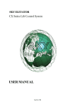
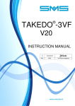
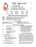
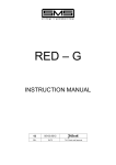
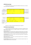
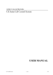
ECO-MPU
APPLICATION GUIDE
WARNING!
READ CAREFULLY CHAPTER 7
"CONNECTING THE
PROGRAMMER"
0
13-02-03
REL.
DATE
R.T. Checking and Approval
CONTENTS
1
INTRODUCTION................................................................................. Page
3
2
GENERAL DESCRIPTION.................................................................. Page
3
3
INPUT / OUTPUT SIGNALS ............................................................... Page
4
4
OPERATION ....................................................................................... Page
6
5
TIMERS............................................................................................... Page
9
6
ALARM MESSAGES........................................................................... Page 11
7
CONNECTING THE PROGRAMMER................................................. Page 12
8
EXAMPLE WIRING DIAGRAM FOR PANEL WITH A.P.B. OPERATION,
2-SPEED ............................................................................................. Page 13
9
EXAMPLE WIRING DIAGRAM FOR PANEL WITH A.P.B. OPERATION,
HYDRAULIC........................................................................................ Page 16
10
EXAMPLE WIRING DIAGRAM FOR PANEL WITH A.P.B. OPERATION
WITH VACON FREQUENCY CONVERTER....................................... Page 20
2
ECO-MPU APPLICATION GUIDE Release 0 dated 13-02-2003
1 – INTRODUCTION
ECO-MPU is a microprocessor system designed, developed and produced by SMS for lifts operation.
Compact and versatile, thanks to the types of functions integrated in its circuit board, it allows minimisation of
the external components required on the control panel.
It is suitable for both hydraulic and traction drive systems, with different types of driving (1 speed, 2 speed
and with ACVV or VVVF speed regulator), with manual or automatic doors.
ECO-MPU is suitable for lift operated by Automatic Push Button (A.P.B.), up to 8 stops, car with single entrance.
2- GENERAL DESCRIPTION
ECO-MPU consists of one microprocessor, which is the heart of the system, and the interface to power
circuits of shaft and car .
The board comprises the following basic components:
• 16-bit microprocessor, with integrated program memory.
2
• E PROM memory, containing the system's programmable parameters (e.g. number of stops, type of
doors, etc.) and any alarm codes.
Parameters can be modified or alarm codes read using the MPU CONSOLE keyboard (or MPU
2
PROGRAMMER – see Chapter7). The data contained in the E PROM are retained in the memory even in
case of a power supply blackout.
ECO-MPU board has to be supplied by 3 ~ 18 VAC: 24VDC voltage for interface circuits and 5VDC voltage
for microprocessor supply are carried out inside the board itself.
The board needs 18VAC three-phase voltage, which is necessary to carry out the control on the 3 phases of
main power supply (to check phase sequence or missing phase). Anyway, it is possible to supply the board
by single-phase 18VAC (terminals 18R - 18S),but in this case you should disable the phase control on the
board by means of the keyboard (Console or Programmer), and eventually install on the control panel a
separate phase control device.
IMPORTANT
Never supply the board at a voltage other than that specified; moreover note that the
negative of the 24 VDC voltage (terminal 0) must NOT be connected to ground.
ECO-MPU has the following functions and components:
• Checking of the phase sequence or missing phases in the three-phase power supply voltage.
• Motor protection by means of thermistors, to be connected directly to the circuit board.
• Monitoring of the status of the safety chain, by means of 5 opto-coupled inputs in conformity with
EN81 HARMONISED NORMS.
• 9 interface relays for controlling of:
− motor contactors (4 relays)
− door motor contactors (1 entrance) (2 relays)
− retiring cam contactor
− "ENGAGED" signal
− power supply consent (alarm relay)
"Clean" contacts of the interface relays are available on the terminal board; for terminals connected
downstream of the safety chain, the insulation distances are in conformity with EN81 HARMONISED
NORMS.
The contacts which control the contactor coils are electrically interlocked.
• 24 inputs 24V for the signals coming from car and landing call buttons, deceleration and stop switches,
service control board, door limit switches, photocells, etc. (see detailed list in Chapter 3). All input circuits
are protected against interference and overvoltages.
• 8 transistor outputs (24V 250 mA) for controlling the car position signalling (Terminal Boards M9 – see
Chapter 3) . All output transistors are protected eventual short circuits by means of PCTs. The maximum
current supplied by each output is 250 mA (which corresponds approximately to the electrical input of 2
lamps 24V 3W connected in parallel).
• 4 transistor outputs (24V 250 mA) for optional functions: (gong, overload, car light, maintenance
speed; available on Terminal Board M1 see detailed list in Chapter 3). External relays with coil 24
VDC, maximum current 50 mA, must be provided for the operation of these outputs.
The remote relay coils must be connected across the relative terminal and 24, as shown in the example in
Fig. 1 for GONG signal. Always connect a recycling diode in parallel with the coil, as shown in Fig. 1.
24
Bobina relè
24VDC – 50mA
Fig. 1
GONG
ECO-MPU APPLICATION GUIDE Release 0 dated 13-02-2003
3
WARNING:
The outputs connected to terminal board M1 do not have short-circuit protection, so any
wrong connection may damage the circuits on the ECO-MPU board, and to the
microprocessor on board itself.
• Car movement control from the panel by means of a switch (BEX) and two buttons (UP, DOWN)
provided directly on the circuit board; this control disables calls and allows the car to be run between two
or more floors chosen by the operator (see Chapter 4).
• Inputs and outputs status displayed by means of LEDs.
The car's position is shown by means of the 8-LEDS placed close to the terminal board M9 of this board.
On the same LEDS can be read the codes of any alarms which have eventually occurred. This is possible
by switching on DGN switch and pressing the UP or DOWN button to scroll them in sequence, if more
than one.
• Connector CN4 (9 pins) for connection of the ECO keyboard; it is used for programming and diagnostic
functions.
WARNING: Read carefully Chapter 7 – CONNECTING THE PROGRAMMER before connecting the
keyboard to connector CN4.
2.1- ARRANGEMENTS
On the board we have foreseen one jumper and some solder point, in order to change easily and directly
some functioning features.
The complete list is the following:
J1
= Always in position 1
SP1
= Operating with MPU CONSOLE always in position 1 (see Chapter 7)
SP2 – SP3
= Connection relay coils AU-AD see Fig. 3 and Fig. 4 in Chapter 4
3 – INPUT/OUTPUT SIGNALS (TERMINAL BOARDS)
4
TERMINAL
CODE
24
LC
MS
OCO
GONG
HSD
TERMINAL
NUMBER
M1 – 1
M1 - 2
M1 - 3
M1 - 4
M1 - 5
M1 – 6
HSU
M1 – 7
AUP
ADP
M1 – 8
M1 – 9
TERMINAL
CODE
EC
PE
TDC
OCI
ROP
TERMINAL
NUMBER
M2 - 1
M2 - 2
M2 - 3
M2 - 4
M2 - 5
EA1
M2 - 6
EA2
M2 - 7
THM1
THM2
M2 - 8
M2 - 9
TERMINAL
CODE
24
DOL1
DCL1
URI
DRI
ULS
DLS
USS
DSS
TERMINAL
NUMBER
M3 - 1
M3 - 2
M3 - 3
M3 - 4
M3 - 5
M3 - 6
M3 - 7
M3 - 8
M3 - 9
DESCRIPTION TERMINAL BOARD M1 (OUTPUTS)
SUPPLY 24VDC(+): outputs common
CAR LIGHT / FAN CONTROL
MID-SPEED CONTROL
CAR OVERLOAD WARNING SIGNAL
GONG SIGNAL
HIGH SPEED RELAY ENABLE (HS)
FROM TOP/BOTTOM SLOW-DOWN SWITCHES
(do not connect for single speed systems – see Picture 4)
UP/DOWN RELAY ENABLE (AU, AD)
FROM TOP/BOTTOM SLOW-DOWN SWITCHES
DESCRIPTION TERMINAL BOARD M2 (INPUTS)
CAR OCCUPIED (load ≥ 1 person)
PHOTOCELL
CONTACTORS FOR DE-ENERGIZATION DELAY
CAR OVERLOAD (load > 110% capacity)
EMERGENCY
OUTER ALLARM 1: if this input opens, the car will stop immediately; for example, you
can connect here the VVVF fault contact. Connect to 24V if unassigned
OUTER ALLARM 2: if this input opens, the car will stop at the end of the actual run;
for example, you can connect here the oil thermostat contact. Connect to 24V if unass
THERMISTORS
DESCRIPTION TERMINAL BOARD M3 (INPUTS)
24VDC SUPPLY (+): input common
END OF RUN DOOR OPENING
END OF RUN DOOR CLOSING
INSPECTION UP BUTTON
INSPECTION DOWN BUTTON
TOP LANDING SLOW-DOWN SWITCH
BOTTOM LANDING SLOW-DOWN SWITCH
UP STOP (DOWN DECELERATION) SWITCH
DOWN STOP (UP DECELERATION) SWITCH
ECO-MPU APPLICATION GUIDE Release 0 dated 13-02-2003
TERMINAL
CODE
24
R0
R1
R2
R3
R4
R5
R6
R7
TERMINAL
NUMBER
M4 - 1
M4 - 2
M4 - 3
M4 - 4
M4 - 5
M4 - 6
M4 - 7
M4 - 8
M4 - 9
TERMINAL
CODE
TERMINAL
NUMBER
SC1
M5 - 1
SC1C
M5 - 2
SEX
M5 - 3
SEXC
M5 - 4
SC2
M5 - 5
SC2C
M6 - 1
SC3
M6 - 2
SC3C
M6 - 3
SC4
M6 - 4
SC4C
M6 - 5
TERMINAL
CODE
18R
18S
18T
0
24
TERMINAL
NUMBER
M7 - 1
M7 - 2
M7 - 3
M7 – 4
M7 – 5
RC
M7 – 6
OS2
OS1
M7 – 7
M7 – 8
M7 - 9
TERMINAL
CODE
CA
AD
AU
CD
DO
DC
CAM
TERMINAL
NUMBER
M8 - 1
M8 - 2
M8 - 3
M8 - 4
M8 - 5
M8 - 6
M8 - 7
M8 - 8
M8 - 9
M8 - 10
M8 - 11
M8 - 12
TERMINAL
CODE
CRE
ECC
ECL
+S
S7
S6
S5
S4
S3
S2
S1
S0
TERMINAL
NUMBER
M9 - 1
M9 - 2
M9 - 3
M9 - 4
M9 - 5
M9 - 6
M9 - 7
M9 - 8
M9 - 9
M9 - 10
M9 - 11
M9 - 12
CS
HS
LS
DESCRIPTION TERMINAL BOARD M4 (INPUTS)
24VDC SUPPLY (+): common inputs
CALL/ SIGNAL LANDING 0
CALL/ SIGNAL LANDING 1
CALL/ SIGNAL LANDING 2
CALL/ SIGNAL LANDING 3
CALL/ SIGNAL LANDING 4
CALL/ SIGNAL LANDING 5
CALL/ SIGNAL LANDING 6
CALL/ SIGNAL LANDING 7
DESCRIPTION TERMINAL BOARD M5 and M6 (INPUTS)
OPTO-INSULATED INPUT AT TOP OF SAFETY CHAIN
(downstream of the OPERATING AUTOMATIC SWITCH)
CONTROL PANEL GROUND
OPTO-INSULATED INPUT, SAFETY CHAIN 1
(downstream of OVERTRAVEL SWITCH, which must be the 1st of the safety chain)
CONTROL PANEL GROUND
OPTO-INSULATED INPUT, SAFETY CHAIN 2
(downstream of SPEED GOVERNOR, SAFETY GEAR, ETC, and the
NORMAL / INSPECTION SERVICE switch)
Input SC2 must stay EVER open during the INSPECTION sevice.
CONTROL PANEL GROUND
OPTO-INSULATED INPUT, SAFETY CHAIN 3
(downstream of CAR STOP CONTROL (if present for existing lifts) and LANDING
DOOR DRAWING IN contacts)
CONTROL PANEL GROUND
OPTO-INSULATED INPUT, SAFETY CHAIN 4
(downstream of CAR DOORS and LANDING DOOR LOCKED contacts)
CONTROL PANEL GROUND
DESCRIPTION TERMINAL BOARD M7 (INPUTS)
BOARD SUPPLY 18VAC 3-phase FROM TRANSFORMER
If supplied by 18VAC single-phase, connect to terminals 18R – 18S
24VDC for INPUTS / OUTPUTS SUPPLY or from BATTERY for BOARD
EMERGENCY SUPPLY
DRIVE CONTACTOR CONTROL
It is possibile to set if input has to be HIGH active (N.O. parallel contacts) or LOW
active (N.C. series contacts)
Not connected
ALARM RELAY - N.O. VOLTAGE FREE CONTACT
(connect in series with operation voltage, upstream of the safety chain)
DESCRIPTION TERMINAL BOARD M8 (OUTPUTS)
COMMON UP/DOWN CONTROLS
DOWN CONTROL
UP CONTROL
Not connected
COMMON HIGH/LOW SPEED CONTROLS
HIGH SPEED CONTROL
LOW SPEED CONTROL
Not connected
COMMON DOOR AND RETIRING CAM CONTROLS
DOOR OPENING CONTROL
DOOR CLOSING CONTRO
RETIRING CAM CONTROL
DESCRIPTION TERMINAL BOARD M9 (OUTPUTS)
COMMON FOR LANDING BUTTONS
“OCCUPIED” SIGNAL SUPPLY: N.O. VOLTAGE FREE CONTACT
COMMON CAR POSITION SIGNAL
CAR POSITION SIGNAL LANDING 7
CAR POSITION SIGNAL LANDING 6
CAR POSITION SIGNAL LANDING 5
CAR POSITION SIGNAL LANDING 4
CAR POSITION SIGNAL LANDING 3
CAR POSITION SIGNAL LANDING 2
CAR POSITION SIGNAL LANDING 1
CAR POSITION SIGNAL LANDING 0
ECO-MPU APPLICATION GUIDE Release 0 dated 13-02-2003
5
4 - OPERATION
ECO-MPU control device is able to operate the electronic floor selector and lift operation in all the
different conditions envisaged: normal operation, inspection operation, adjustment operation and
rescue operation.
4.1 ELECTRONIC FLOOR SELECTOR
For this purpose the microprocessor uses the signals from two switches mounted on the car to determine the
car position during any run.
These switches are connected to the USS and DSS inputs.
The selector release and the eventual deceleration of the car, is controlled by DSS during UP travel and by
USS opens during DOWN travel.
Car stop at the landing, if car has slowed down, is controlled by USS during UP travel and by DSS during
DOWN travel (the complete stop occurs when both switches are engaged.
The floor selector resets its phase each time the car reaches the top or bottom floor: this is ensured by two
switches, an upper limit switch (ULS) and a lower limit switch (DLS), which directly control deceleration and
position the selector at the relative floor (top or bottom).
The explanations which follow and Figure 2, which shows the switching sequence of USS, DSS, ULS and
DLS, refer to N.C. switches (normally closed, which opens when tripped by the magnet).
USS
DSS
ULS
DLS
N
= magnet
~2 cm
Z2
2
X2
Z1
X1
Y1
Y2
1
~2 cm
0
Fig. 3
6
X1 = UP deceleration
Y1 = DOWN deceleration
Z1 – Z2 = door zone
X2 = UP stop
Y2 = DOWN stop
ECO-MPU APPLICATION GUIDE Release 0 dated 13-02-2003
Limit switches ULS and DLS must only be of N.C. type, while for deceleration and stopping (USS and DSS) it
is possible to program both type N.O. (normally opened, which closes when tripped by the magnet) or N.C.
type, by means of MPU CONSOLE. In this case both switches must be provided of the same type
SMS supplies the circuit boards already programmed for the N.C. type.
The floor selector automatically resets its phase by sending the car to the top or bottom floor every time
power is returned after a shutoff or when normal operation restarts after an alarm reset; as for example after
a travel time alarm or motor thermistor trip, incorrect phase sequence, etc..
The reset operation is different depending on car position and the type of driving:
• Car outside the bottom landing deceleration zone: starts down at high speed and stops when the switch
DLS opens (1-speed lift); otherwise it decelerates when DLS opens and stops by opening of USS and
DSS (2-speed lift).
• Car inside the bottom landing deceleration zone but not at exact floor level:
− 1 or 2-speed Lift:
starts up at high speed and stops when ULS opens (1-speed lift), or slows
down when ULS opens, and stops completely when USS and DSS opne
(2-speed lift).
− Hydraulic lift or with speed regulator (ACVV o VVVF)
starts down at low speed and stops at the
bottom landing when USS and DSS open.
If the phase reset cycle does not terminate successfully, due to door problems or other faults, the cycle
repeats five times, after which the car remains out of service and an alarm message is generated.
4.2- NORMAL OPERATION
Provides full control of the logic operation in A.P.B. lifts.
4.3- INSPECTION OPERATION
During INSPECTION operation, the maintenance technician operates the elevator from the car roof (dead
man).
The microprocessor monitors the inspection board control state via input SC2 (SC2 = 0 → inspection in
progress) and controls car movement when inputs URI (UP) or DRI (DOWN) are activated via a contact of
the pendant control buttons.
Inspection run can be performed in high or low speed (programmable by MPU CONSOLE).
For 2-speed lift inspection is performed in high speed but low speed control is actuated for 3 seconds
anyway, after which the system switches to high speed: this is to allow the operator to approach a specific
point with low speed precision if necessary.
4.4- ADJUSTMENT OPERATION
During ADJUSTMENT operation, the maintenance technician can control the car movement from the control
panel, while normal calls to the elevator and door opening are excluded. A switch (BEX) and two buttons
(UP, DOWN) are provided for this purpose.
With the switch BEX ON the adjustment mode is enabled while normal operation is disabled.
If the BEX switch is closed during car movement, adjustment mode is enabled only after the car has arrived
at the landing and the doors have been opened.
The UP/DOWN buttons control car movement UP or DOWN; the car moves at high speed while the button is
held down. When the button (UP or DOWN) is released, high speed drive continues until the car encounters
a deceleration zone, at which point it decelerates and stops at the relative landing.
If the button for the direction opposite to that of the lift's travel direction (e.g. DOWN while the lift is going up),
is pressed, the system stops immediately.
4.5- RESCUE OPERATION
Emergency operation, to bring the car to the floor when the mains power has failed, is enabled by closing the
ROP input.
When ROP=1, the phase control is immediately disabled, after which the operating mode is different for
hydraulic and traction lifts.
a) Hyraulic lifts 5 seconds after ROP is activated, the lift starts a downward travel as if automatically
instructed to return to the bottom floor. When it reaches the floor, the automatic doors (if
installed) open, and once they are open no further operation is possible until the ROP
input returns to 0, after which the lift goes back into service, with a reset procedure.
b) Traction lifts
5 seconds after ROP is activated, the circuit board gives the command for downward
travel (though the direction the car will take depends on the load).
The lift stops (without deceleration) at the first stopping zone it reaches, i.e. when USS
and DSS are both tripped; at this point, the automatic doors (if installed) open, and once
they are open no further operation is possible until the ROP input returns to 0, after which
the lift goes back into service, with a resynchronisation procedure.
ECO-MPU APPLICATION GUIDE Release 0 dated 13-02-2003
7
In the different operating modes described above, the start cycle is initiated first of all by actuating the CAM
output when the doors are closed and then, 200 milliseconds after closure of input SC4 (landing door
locked), the drive starts, always at high speed (except for special cases) by actuating AU (UP) or AD
(DOWN) together with HS (high speed).
Deceleration is controlled by opening HS and actuating output LS (low speed).
The car stops at the landing when LS opens. AU / AD can be opened at the same time as LS (for 2-speed or
hydraulic lifts), or can be delayed for systems with speed regulator ACVV or VVVF.
The delay can be programmed using a special internal timer (see Chapter 6 TIMERS - TOC timer), or if the
ACVV or VVVF drive has an output which controls the opening of the contactors. In this case connect this
contact (which must close when the lift is moving and open, with delay, when it stops at a floor) to input TDC:
this means that opening of the AU / AD relays (and thus of the motor contactors) will be triggered by the
speed regulator at the right moment.
To ensure stopping at the top and bottom landings even if the microprocessor is disabled, the top and
bottom landing limit switches (ULS and DLS) act like input signals for the controller, but also directly trip the
HS (high speed) output relay for 2-speed, speed-regulated or hydraulic lift systems, or directly trip the AU
(UP) or AD (DOWN) output relays for 1-speed lifts.
For this purpose terminals AUP, ADP, HSU, HSD and solder points SP1 and SP3 are foreseen on the board.
Figures 3 and 4 show the connections which must be wired in the above two cases.
ULS
DLS
SP1 and SP3
IN POSITION 2
ULS
DLS
AU
BOARD
QINB
ULS
AUP
ADP
24
HSU
AD
HSD
Fig.3: Connections for terminals AUP,
ADP, HSU, HSD and solder
points SP1 and SP3 for 1-speed
systems
HS
DLS
SP1 and SP3
IN POSITION 1
ULS
BOARD
QINB
8
DLS
AUP
AU
ADP
AD
24
D
U
HSU
HSD
HS
Fig.4: Connections for terminals AUP,
ADP, HSU, HSD and solder
points SP1 and SP3 for 2-speed,
speed-regulated or hydraulic
drive systems.
ECO-MPU APPLICATION GUIDE Release 0 dated 13-02-2003
5 – TIMERS
For optimal control of the elevator during operation many timers are required; some of these are operational
in the sense that they control operating sequences, while others are protective in function, that is, they
monitor and detect faults which avoid successful termination of operational sequences.
Some can be programmed via keyboard, others are set, that is, the value is fixed in the CPU’s internal
program memory.
The following tables detail the functional timers:
5.1 – OPERATION TIMERS
CODE
TC
DESCRIPTION
TIME
TYPE
START DELAY
It avoids immediate car start after a stop due to any cause (stop at landing, safety trip,
alarm condition, etc.)
0 ÷ 20
sec
PROGR
1 ÷ 60
sec
PROGR
0.0 ÷ 2.0
sec
PROGR
0.0 ÷ 2.0
sec
PROGR
TO
CAR OCCUPIED DELAY
The classic delay which controls the “occupied” signal and excludes other calls from
landing panels.
TS
STOP DELAY
The delay between opening of the stop switch and its actual effect, that is, the car stops
after a time set by this delay.
Using this delay, it’s possible to have always the same length of stop magnets,
whatever is the kind or speed of the lift.
RETIRING CAM DELAY
The delay between the contactors opening and the opening of the relay which controls
TRPR the retiring cam.
For example it can be used in 1-speed systems, to control retiring cam de-energization
when the car is already stopped at floor (at the stopping phase end).
TAP
DOOR OPEN DELAY
The delay between the opening of the contactors and the door open command.
For example it can be used in systems with automatic doors and retiring cam, to have
that the door opening starts when the retiring cam is already de-energized.
0.0 ÷ 2.0
sec
PROGR
TG
GONG TIME
0.1 ÷ 3.0
The time for which the car at landing gong control is active, from when the doors start to
sec
open, or from when the car is stopped, in case of manual doors.
PROGR
TFL
FAN AND/OR CAR LIGHT DELAY
Controls the LC output and determines for how long this output is active after the
occupied signal is disabled.
1 ÷ 255
sec
PROGR
TAR
AUTOMATIC RETURN ACTIVATION DELAY
1 ÷ 15
min
PROGR
TOC
CONTACTOR OPEN DELAY
0.0 ÷ 2.0
Used in speed regulated systems (type ACVV or VVVF) to allow contactor opening only
sec
when the motor has already stopped.
PROGR
TES
RESCUE OPERATION STOP DELAY
The equivalent of the TS timer for rescue operation.
PROGR
ECO-MPU APPLICATION GUIDE Release 0 dated 13-02-2003
0.0 ÷ 2.0
sec
9
5.2 – PROTECTION TIMERS
CODE
DESCRIPTION
TIME
TYPE
TDO
MAX. DOOR OPENING TIME
If the doors do not terminate their opening travel within the set time, the door motor
control is cancelled.
1 ÷ 60
sec
PROG
TDC
MAX. DOOR CLOSING TIME
If the doors do not terminate their closing travel within the set time, the door motor
closing command is cancelled, and doors reopen waiting for a new calls.
If the timer trips while the doors are closing during the reset cycle, five attempts at
closing are made, after which the car remains stopped with the doors open.
1 ÷ 60
sec
PROG
THS
HIGH SPEED MAX. TRAVEL TIME
To ensure that the programmed time does not depend on the total travel of the lift, the
counter starts again from zero every time a landing is passed.
1 ÷ 45
sec
PROG
TLS
LOW SPEED MAX. TRAVEL TIME
Active even during hydraulic lift re-levelling
1 ÷ 45
sec
PROG
TRO
RESCUE OPERATION MAX. TIME
If the rescue operation do not terminate its cycle within the set time, it is stopped.
To resume normal operation, the opening of the ROP input is necessary.
2 ÷ 15
min
PROG
TPE
PHOTOCELL BEAM BROKEN TIME
It doesn’t make any effect, only an alarm code is shown.
20 sec
SET
TRC
CONTACTOR OPENING CONTROL
The timer trips if the RC input (drive contactors) does not open within two seconds of
the contactor open control (de-energising of outputs AU / AD).
2 sec
SET
TCB
CAR DOOR CLOSURE AND LANDING DOOR BLOCKAGES CONTROL
The timer trips at drive start if, with the doors completely closed (input SC3 energised
and input DCL1 not active), input SC4 does not energise within 2 seconds.
2 sec
SET
TAC
CONTACTOR CLOSURE CONTROL
The timer trips at drive start if, with the doors blocked (input SC4 energised), input RC
does not energise within 2 seconds.
2 sec
SET
TSM
DRIVE START CONTROL
The timer trips at drive start if, after closure of the contactors, the car does not exit from
the stop zone within a few seconds (5 seconds for traction lift, 8 seconds for hydraulic
lift)
If a protection timer trips an alarm message is issued.
The full list of alarm messages is given in the Chapter 6.
10
ECO-MPU APPLICATION GUIDE Release 0 dated 13-02-2003
5 sec
SET
8 sec
6 – ALARM MESSAGES
DESCRIPTION
ALARM MESSAGE
DGN CODE LED
S7÷S0
S7 S6 S5 S4 S3 S2 S1 S0
PHASE SEQUENCE ERROR OR
PHASE FAILURE
OPERATING VOLTAGE FAILURE
EXTERNAL ALARM 1
Any of these alarm messages shuts down the system immediately.
When normal operation is resumed, the elevator automatically
resets before returning to service.
The number of alarm events is counted (up to 31).
HIGH SPEED TRAVEL TIME TRIP
LOW SPEED TRAVEL TIME TRIP
HYDRAULIC RE_LEVELLING
TIME TRIP
CONTACTOR OPENING FAILURE
Any of these alarm messages shuts down the system immediately.
The lift can return to normal operation only after a manual RESET
using the BEX switch on the board.
By closing and opening the BEX switch, the elevator will be reset
and return to normal operation
OVERTRAVEL MEMORY
DOOR CLOSING TIMER TRIPPED
DOOR OPENING TIMER TRIPPED
WRONG OPERATION OF
☺☺☺☺☺☺☺☻
-----
☺☺☺☺☻☺☺☻
☺☺☺☺☻☺☻☺
☺☺☺☺☻☺☻☻
☺☺☺☺☻☻☺☺
☺☺☺☺☻☻☻☺
☺☻☺☺☺☺☺☺
☻☺☺☺☺☺☺☺
☺☺☺☺☻☻☺☻
RESET SWITCH
TDC INPUT CLOSURE FAILURE
(from ACVV or VVVF speed gulator)
These alarm messages do NOT shut down the system.
The number of alarm events is counted (up to 31).
☺☺☺☺☻☺☺☺
PHOTOCELL BEAM BROKEN OR
---
NOT ACTIVE
FOR MORE THAN 20 SECONDS
DOOR CLOSURE OR
LANDING DOOR LOCK FAILURE
CONTACTOR CLOSURE FAILURE
NO MOVEMENT AT START
These alarm messages do NOT shut down the system.
The number of alarm events is counted (up to 31).
The landing at which the alarm event has occurred is also stored in
the memory
☺☺☺☺☺☺☻☺
☺☺☺☺☺☻☺☺
☺☺☺☻☺☺☺☺
THERMISTOR TRIPPED
This alarm message shuts down the system, immediately or only at
the end of the current travel (programmable).
When normal operating conditions are achieved, that is, the motor
temperature drops below the trip threshold, the elevator can return
to service automatically after 15 minutes, or await a manual
RESET by means of the BEX switch: this choice can be made with
the keyboard. When the elevator returns to normal operation the
reset cycle is run anyway.
The number of alarm events is counted (up to 31).
☺☺☺☺☻☻☻☻
EXTERNAL ALARM 2
This alarm message shuts down the system only at the end of the
current travel.
When normal operating conditions are achieved the elevator
returns to service automatically without running a reset cycle.
The number of alarm events is counted (up to 31).
---
RESET CYCLE FAILURE
This alarm signal indicates that the elevator cannot enter service
because the reset cycle will not terminate successfully.
To try again, it’s necessary to switch the power supply off and then
on.
The number of alarm events is counted (up to 31).
☺☺☻☺☺☺☺☺
DGN CODE =
Indicates which number is shown on a series of LEDS which normally indicate the car
position, when the DGN switch is ON.
No Led on means <<NO ALARM>>
☺ = Led OFF , ☻= Led ON
It is important to underline that for hydraulic lifts in an alarm condition (even alarms which put the lift out of
service) the automatic return to bottom landing within 15 minutes, remains active.
ECO-MPU APPLICATION GUIDE Release 0 dated 13-02-2003
11
7 – CONNECTING THE PROGRAMMER
Lift specification can be programmed on ECO-MPU by means of 2 different keyboard:
MPU CONSOLE, with alphanumeric display, or with MPU-PROGRAMMER with 5 7 segments numeric
display .
To connect correctly the keyboard MPU CONSOLE simply connect it with the cable supplied by SMS,
checking, check that the following conditions are met:
•
Jumper JP1 set on 1
•
Solder point SP1 set on 1
To connect correctly the keyboard MPU PROGRAMMER, check that the following conditions are met:
•
Jumper JP1 set on 1
•
Solder point SP1 set on 2
In addition, an adapter to which the MPU PROGRAMMER cable can be connected must be fitted to
connector CN4.
This adapter, code 302.06.ADAT1 (see Fig. 5), must be ordered separately from SMS.
Fig. 6 – MPU PROGRAMMER ADAPTER, code 302.06.ADAT1
For more detailed information about the operation of the MPU PROGRAMMER, refer to the user's manual
supplied with the programmer itself.
12
ECO-MPU APPLICATION GUIDE Release 0 dated 13-02-2003
8 – EXAMPLE WIRING DIAGRAM FOR PANEL WITH A.P.B. OPERATION,
2-SPEED
ECO-MPU APPLICATION GUIDE Release 0 dated 13-02-2003
13
14
ECO-MPU APPLICATION GUIDE Release 0 dated 13-02-2003
ECO-MPU APPLICATION GUIDE Release 0 dated 13-02-2003
15
9 – EXAMPLE WIRING DIAGRAM FOR PANEL WITH A.P.B. OPERATION,
HYDRAULIC
16
ECO-MPU APPLICATION GUIDE Release 0 dated 13-02-2003
ECO-MPU APPLICATION GUIDE Release 0 dated 13-02-2003
17
18
ECO-MPU APPLICATION GUIDE Release 0 dated 13-02-2003
With regard to this example of control panel for hydraulic system, note that relays RL1, RL2 and RL3, which
make up the safety circuit for re-levelling operation, must be "forced guided" or "linked contact" safety relays,
or mini contactors.
RL4, on the other hand, is simply a control relay and may be a mini-relay: it must always be excited, except
when the safety circuit which allows the re-levelling operation is out of service. In this case, the MPU board
detects the potential danger through breaking of the RL4 contact connected to input EA2.
11.1 - HYDRAULIC SYSTEM SWITCHES
Compared to electric systems (see Fig.2), for hydraulic systems there is an extra switch to control the relevelling zone with safety circuit (RZS). The contact of this switch must be N.O. (closed at the floor).
USS
DSS
ULS
DLS
RZS
N
= magnet
~2 cm
W1
Z2
2
X2
Z1
W2
X1
Y1
Y2
1
~2 cm
0
X1 = UP deceleration
Y1 = DOWN deceleration
Z1 – Z2 = door zone
W1 – W2 = re-levelling zone
X2 = UP stop
Y2 = DOWN stop
Fig. 6
ECO-MPU APPLICATION GUIDE Release 0 dated 13-02-2003
19
10 – EXAMPLE WIRING DIAGRAM FOR PANEL WITH A.P.B. OPERATION,
WITH VACON FREQUENCY CONVERTER
20
ECO-MPU APPLICATION GUIDE Release 0 dated 13-02-2003
ECO-MPU APPLICATION GUIDE Release 0 dated 13-02-2003
21
22
ECO-MPU APPLICATION GUIDE Release 0 dated 13-02-2003
For further clarification and advice contact:
SMS SISTEMI e MICROSISTEMI s.r.l. (Gruppo SASSI HOLDING)
Cap. Soc. 260.000 i.v.
Via Guido Rossa, 46/48/50 40056 Crespellano BO
R.E.A 272354 CF - Reg. Imprese Bo 03190050371 P.IVA IT 00601981202
Tel. : +39 051 969037 Fax : +39 051 969303 Technical Service: +39 051 6720710
Web : www.sms.bo.it E-mail : [email protected]
ECO-MPU APPLICATION GUIDE Release 0 dated 13-02-2003
23