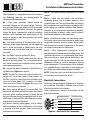
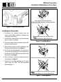
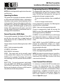
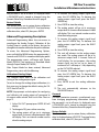
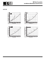
1
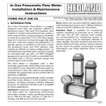
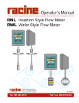
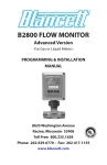
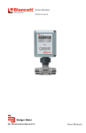
MR Flow Transmitter
Installation & Maintenance
Instructions
FORM #HLIT 306
DIVISION OF RACINE FEDERATED INC.
8635 Washington Avenue • Racine • Wisconsin 53406-3738
TEL 1-800-HEDLAND • FAX 1-800 CHK-FLOW
I. INTRODUCTION
The MR Flow Transmitter is a state-of-the-art,
microprocessor based variable area flow meter.
It combines the rugged proven technology of a
piston-type, variable area flow meter with solid state
circuitry including:
•
•
•
•
Non-contact sensor electronics
Electronic signal conditioning circuit
Digital flow rate and total indication
Proportional analog output
The product is sealed against industrial contamination
by a NEMA 12 and 13 (IP 52/54) rated enclosure and is
available for either liquid or gas service.
The MR Flow Transmitter is capable of calculating
and displaying both flow rate and total accumulated
flow. The flow rate and total flow can be displayed in
any of the user selectable measurement units. The
monitor’s large 8 digit numeric liquid crystal display
makes extended range viewing practical. The second
8 character alphanumeric display provides for
selectable units viewing in RUN mode and prompts
for variables in PROGRAM mode.
All MR Flow Transmitters come pre-calibrated from
the factory. However, the unit may be adjusted
by the user to meet specific system requirements.
Calibration parameters are included for:
• Specific gravity compensation (all fluids)
• Viscosity compensation (petroleum-based fluids)
• Pressure and temperature compensation
(pneumatic applications)
US Patent 7,130,750
Figure 1 - MR Flow Transmitter
All meters include an analog output that can be
configured for 0-5 Vdc, 0-10 Vdc, or 4-20 mA current
loop.
Applications for the MR Flow Transmitter include:
• Bearing lubrication
• Case drain verification
• Gun drill and machine cooling
• Pump flow outputs
Page 1
MR Flow Transmitter
Installation & Maintenance Instructions
II. SPECIFICATIONS
Enclosure Rating
• NEMA 12 & 13 (IP 52 & 54)
Operating Temperature
• Fluid: -20 °F to +240 °F (-29 °C to +116 °C)
• Ambient: -20 °F to +158 °F (-29 °C to +70 °C)
Environmental
• Humidity: 0-90% non-condensing
Pressure Rating Aluminum/Brass
• Liquids (¼” to 1-½”): 3500 psi (241 bar)
maximum with a 3:1 safety factor
• Gases (¼” to 1-½”): 1000 psi (69 bar)
maximum with a 10:1 safety factor
Pressure Rating Stainless Steel
• Liquids (¼” to ½”): 6000 psi (414 bar)
maximum with a 3:1 safety factor
• Liquids (¾” to 1-½”): 5000 psi (345 bar)
maximum with a 3:1 safety factor
• Gases (¼” to 1-½”): 1500 psi (103 bar)
maximum with a 10:1 safety factor
Accuracy
• ±2% of full scale
Repeatability
• ±0.5%
Pressure Drop
• See Appendix for specific meter information
Electrical
Power Requirement:
• 0-5 Vdc Output 10-30 Vdc @ 0.75W maximum
• 0-10 Vdc Output 12-30 Vdc @ 0.75W maximum
• 4-20 mA Output loop-powered, 30 Vdc maximum
Power Consumption:
• 25 mA maximum
Analog Outputs:
• 0-5 Vdc and 0-10 Vdc into 10,000 Ohms minimum
• 4-20 mA into 1000 Ohms maximum (see Figure 2)
Circuit Protection:
• Reverse polarity and current limiting
Transmission Distance:
• 4-20 mA limited by cable resistance
• 0-5 Vdc 1000 feet (300 m) maximum
• 0-10 Vdc 1000 feet (300 m) maximum
Isolation:
• Inherently isolated from the piping system
Rate and Totalization Display
• Fixed or toggle modes of operation for rate and
totalizer display
• 8 digit, .70” high numeric display for rate and total
• 8 digit, .34” high alphanumeric display for units
and setup
Temperature Drift
• 50 ppm / °C (maximum)
Analog Output
• Resolution - 1:4000
Compliance
• Meets the requirements of EN61000-6-4 for a
Class A product for emissions and EN61000-6-2
for immunity tests of an ISM product.
Dimensions
• See Appendix
Figure 2 - Load Limitations (4-20 mA only)
Page 2
Form #HLIT 306 10/10
MR Flow Transmitter
Installation & Maintenance Instructions
III. INSTALLATION
CAUTION
CAUTION
This product should be installed and serviced
by technically qualified personnel trained in
maintaining industrial class flow instrumentation
and processing equipment.
Air/gas meters are NOT oxygen cleaned. Use
with oxygen may cause hazardous or explosive
conditions that may cause serious personal injury
and/or damage to the equipment.
CAUTION
CAUTION
Read instructions thoroughly before installing the
unit. If you have any questions regarding product
installation or maintenance, call your local supplier
for more information.
This meter may contain residual amounts of test
fluid at the time of shipment. This fluid should be
removed prior to installation as the fluid may be
incompatible or hazardous with some liquids or
gases. Failure to follow these instructions could
result in damage to the equipment.
WARNING
Disconnect electrical power before opening wiring
enclosure. Failure to follow these instructions could
result in serious personal injury or death and/or
damage to the equipment.
WARNING
All wiring should be installed in accordance with the
National Electrical Code® and must conform to any
applicable state and local codes. Failure to follow
these instructions could result in serious personal
injury or death and/or damage to the equipment.
Form #HLIT 306 10/10
CAUTION
This standard meter is unidirectional. Attempts
to flow fluids in the opposite direction of the flow
arrow will result in the meter acting as a check valve,
creating a deadheading situation. If the differential
pressure magnitude is great enough, damage to
the internal parts of the meter will result.
Page 3
MR Flow Transmitter
Installation & Maintenance Instructions
Installation Recommendations
The transmitter is a simple device to install. However,
the following measures are recommended for
reliable, trouble-free operation:
Do - Align pipe accurately. Piping should be
accurately aligned and of correct length. The high
pressure body of the transmitter can withstand shock
and flow/pressure pulsation. However, the piping
should be firmly supported by external mounting
brackets, both upstream and downstream of the
meter, to avoid any pipe flexing actions that could
reduce meter life.
Do - Use rigid mounting. If the transmitter inlet or
outlet are to be rigidly mounted, and the opposing
port is to be connected to flexible hose, the end
connected with the flexible hose must be rigidly
mounted.
Do - Use Teflon® tape for sealing NPT fitting.
Do - Install unions. Install a union near the inlet or
outlet of the transmitter. This will facilitate quick,
easy meter removal and inspection during periodic
maintenance procedures.
Do - Ensure the fluid is traveling in the direction of
the flow arrow (Figure 5 on page 6).
NOTE: The MR Flow Transmitter display board can be
rotated 180° for optimal viewing. Simply remove the
MR Flow Transmitter cover, disconnect the ribbon cable,
rotate the display board 180°, reconnect the ribbon
cable, and reinstall cover. See Figure 8 on page 8 for
cover screw tightening sequence.
Do - Use at least a 200 mesh (74 micron) filter. The
transmitter will allow particulate to pass that would
jam most valves and flow controls. Systems that do
not have filtration should be equipped with at least
a 200 mesh (74 micron) filter. Most hydraulic systems
already have much finer filtration.
Dirt, ferrous metal or sealing agents, such as Teflon®
tape may lodge and cause malfunction. If the meter
is jammed at a fixed position, follow cleaning and
maintenance instructions.
Page 4
Don’t - Use thread locking compounds as thread
sealant.
Don’t - Install the transmitter near turbulence
producing fittings such as elbows, reducers, close
coupled valves, etc. The transmitter does not require
flow straighteners or special lengths of straight inlet/
outlet piping to stabilize turbulent flow patterns.
However, to assure maximum operational reliability,
avoid installation of elbows, valves and/or reducers
immediately adjacent to the meter inlet.
Don’t - Install the transmitter near fast-acting valves.
Fast-acting valves have the potential to create high
magnitude hydraulic pressure spikes. These spikes
can damage the internal components of the meter,
resulting in inaccuracies or malfunction.
Don’t - Allow unidirectional transmitters to be
operated against the direction of the flow arrow. The
standard transmitter is a unidirectional flow meter.
The piston acts as a check valve to block flow in the
reverse direction. This causes an excessive pressure
differential, which can result in damage to internal
meter components. The transmitter is also available
in a modified design, which offers a reverse flow bypass feature to accommodate bi-directional flow.
NOTE: Transmitters with a reverse flow by-pass feature
are available. Consult factory for details.
Electrical Connections
Cable may be shortened or lengthened as required
by installation. The cable is soldered directly to the
electrical connector at the factory.
Cable replacement requires disassembly of the
electrical connector.
DC Output Connection
Loop Power Connection
2 Black: No Connection
(-) 4-20 mA Out
3 Green: 0 VDC
No Connection
1
Red:
(+) DC Power
(+) 4-20 mA In
4 White: 0-5 VDC or 0-10 VDC Output No Connection
Figure 3 - Electrical 4-Pin Connection
Form #HLIT 306 10/10
MR Flow Transmitter
Installation & Maintenance Instructions
CAUTION
The flow transmitter is designed to operate only
one of its three outputs at a time (i.e., 0-5 Vdc or
0-10 Vdc or 4-20 mA). Connecting multiple outputs
simultaneously will result in inaccurate output
signal levels.
Schematics
The transmitter can be wired in various configurations
to allow interface with many different types of data
collection and control instrumentation.
Schematics 1 & 2 represent typical wiring for a target
powered by either AC power or DC supply.
Schematics 3 & 4 will be utilized when the flow
transmitter is operated with loop-powered process
indicators or data loggers that do not have external
sensor excitation available.
Black
External DC Sensor
Excitation
Green
4-20 mA Input
Red
White
Example: Chart Recorder
Schematic 1: 4-20 mA connection using target
power supply
Sensor Excitation
Black
0-5 VDC Input
Green
0-10 VDC Input
Red
Ground
White
Example: Chart Recorder
Schematic 2: 0-5 Vdc or 0-10 Vdc connection using
target power supply
Fuse: 0.05 A Fast
Black
Green
Red
Excitation
Voltage
4-20 mA Input (+)
4-20 mA Input (-)
White
Example: Chart Recorder
Schematic 3: 4-20 mA connection using target
external power supply
Fuse: 0.05 A Fast
Black
0-5 VDC Input
Green
0-10 VDC Input
Red
Ground
White
Excitation Voltage
Example: Chart Recorder
Schematic 4: 0-5 Vdc or 0-10 Vdc connection using
target external power supply
Figure 4 - Terminology
Form #HLIT 306 10/10
Page 5
MR Flow Transmitter
Installation & Maintenance Instructions
Place wrench on transmitter flats
on the same side plumbing is being tightened
Figure 5 - Flow Direction Arrow
Installing the Transmitter
1. Disconnect the electrical power from the
target system before making or changing any
transmitter connections.
2. Use 0.05A fast acting fuse if non-current limited
power sources are utilized.
Never place wrench on transmitter flats
opposite plumbing being tightened
Figure 6 - Installing Meter
3. Terminate cable shield connection at either DC
ground or earth ground.
4. Mount the transmitter so fluid is traveling in the
direction of the flow arrow. See Figure 5.
5. Install unit in desired location. Use wrench on
transmitter flats to hold the unit in place during
installation. DO NOT TURN the transmitter using
the wrench. See Figure 6.
6. After installation, rotate transmitter by hand to
view display. See Figure 7.
Rotate transmitter by hand to view flow display
7. Capture the zero flow position on the meter
cone using the ZERO CAPTURE procedure
found on page 9.
Never use wrench on transmitter flats to rotate
transmitter body when viewing flow display
Figure 7 - Rotating Meter
Page 6
Form #HLIT 306 10/10
MR Flow Transmitter
Installation & Maintenance Instructions
IV. OPERATION
Programming Operation (PROGRAM) Mode
NOTE: Refer to the Appendix for application information
and fluid charts.
The programming mode allows the user to change
the configuration and adjust the calibration of the
meter. The MR Flow Transmitter has two types of
configuration changes in program mode:
Operating the Meter
The monitor has two modes of operation, referred to
as RUN mode and PROGRAM mode as indicated on
the display screen readout. Normal operation will be
in the run mode. To access the program mode, press
the MENU key until the first programming screen
DISPLAY appears. (PROGRAM appears on left side of
display.) After programming the meter, a password
may be entered to prevent unauthorized access or
changing of the setup features.
Normal Operation (RUN) Mode
During normal operation, the display will show RUN
and the flow rate, total flow, or toggle back and
forth between the two as defined by the DISPLAY
configuration.
The four buttons have the following function in RUN
mode:
MENU - Selects programming mode.
UP ARROW - No function.
RIGHT ARROW - No function.
• To view or change selections from a predefined
list
• To view or change numeric entries
During programming operation, the following four
button functions are provided:
MENU - Enters and exits programming mode.
Change to programming mode by pressing the
MENU key once. The mode indicator on the display
will change from RUN to PROGRAM.
UP ARROW - Use the UP ARROW key to scroll through
the configuration choices in a bottom-to-top order.
For numeric setup, this button increments numeric
values.
RIGHT ARROW - Use the RIGHT ARROW key to scroll
through the configuration choices in a top-tobottom order. For numeric setup, this button moves
the active digit to the right.
ENTER - Used to enter menus, to change configurations
and to save programming information.
ENTER - The current total can be manually stored
in the monitor’s flash memory. Press and hold the
ENTER key for 2 seconds. The display will respond
with a flashing TOTALSVD and then will return to RUN
mode.
NOTE: If any input value exceeds the meter’s capabilities,
the LIMIT indicator will begin to flash indicating an
invalid entry. Press ENTER once to return to the entry
screen to reenter the value.
RESET TOTAL - To reset the monitor’s total display,
press the MENU and ENTER keys simultaneously
until TOTALRST starts to flash. The TOTALRST will stop
flashing and the display will return to RUN mode at
the conclusion of the reset procedure.
Cover Removal/Reinstallation
Form #HLIT 306 10/10
It is necessary to remove the MR Transmitter cover
to access the programming keys. Use a Phillips
screwdriver to remove the 4 screws that hold the
cover in place, turning them counterclockwise. When
programming is completed, reinstall the cover. To
properly seat the built-in cover gasket, tighten the
cover screws clockwise in a crisscross pattern as
shown in Figure 8 on page 8.
Page 7
MR Flow Transmitter
Installation & Maintenance Instructions
The unit will automatically advance.
4b. If current selection must change, press either
arrow key to scroll through the available choices.
Press ENTER to confirm your selection.
The unit will automatically advance.
5. To exit programming, press the MENU button.
The display will change to RUN mode.
Numeric Value Entry Procedure
Figure 8 - Cover Screw Tightening Sequence
Programming Procedures
The MR Transmitter has been programmed at
the factory according to the specifications that
were provided at the time of order. No further
programming is required unless a change has
occurred in the original specifications.
If programming is required, the MR Transmitter allows
two basic sets of programming procedures: List Item
Selection and Numeric Value Entry.
List Item Selection Procedure
NOTE: If you are already in PROGRAM mode and the
selection to be viewed or changed is already displayed,
proceed to step 3 below. If you are in PROGRAM mode
and the selection to be viewed or changed is not
displayed, press the UP or RIGHT ARROW key and repeat
pressing until the desired selection appears. Proceed to
step 3.
1. Press MENU.
PROGRAM appears in the lower left-hand corner and
DISPLAY appears.
2. Press the UP ARROW or RIGHT ARROW key to
move to the desired selection.
3. Press ENTER to view the current selection.
4a. If the current selection is desired, press ENTER to
confirm.
Page 8
NOTE: If you are already in PROGRAM mode and the
desired selection is displayed, proceed to step 3 below.
If you are in PROGRAM mode and the desired selection
is not displayed, press the UP or RIGHT ARROW key and
repeat pressing until the desired selection appears.
Proceed to step 3.
1. Press MENU.
PROGRAM appears in the lower left-hand corner and
DISPLAY appears.
2. Press the UP ARROW or RIGHT ARROW key to
move to the desired selection.
The current numeric value for this selection appears
in the upper section of the display.
3a. If the current displayed value is desired, press
ENTER. The left most programmable number
begins to flash. Press ENTER again to confirm and
keep the current setting.
The unit will automatically advance.
3b. If the current selection must change, press ENTER.
The left most programmable number begins to
flash. Use the UP ARROW key to scroll through
the digits 0-9 and change the flashing digit to
the desired value. Use the RIGHT ARROW key to
move the active digit to the right. Continue using
the UP and RIGHT ARROW keys until all desired
digits are selected.
4. Press ENTER to confirm your selection.
The unit will automatically advance.
5. To exit programming mode, press the MENU key.
The display will change to RUN mode.
Form #HLIT 306 10/10
MR Flow Transmitter
Installation & Maintenance Instructions
Programming Flow Chart
The programming flow chart on pages 12 and 13 will
aid understanding of the menu structure of the MR
Flow Transmitter. It will also help with understanding
the available configuration selections.
that would exceed the 8 digit display capacity. Table
2 lists the available selection choices. Its displayed
name is TOTL EXP and is viewed or changed using the
List Item Selection Procedure found on page 8.
E-2
Total display number indicates
increments of 0.01 unit
Display Mode
The meter can display RATE (flow rate) or TOTAL (total
accumulated flow) or alternate between BOTH rate
and total. Its displayed name is DISPLAY and is viewed
or changed using the List Item Selection Procedure
found on page 8.
E-1
Total display number indicates
increments of 0.1 unit
E0
Total display number indicates
increments of 1 unit (Factory Default)
E1
Total display number indicates
increments of 10 unit
Rate Units of Measure
The meter allows the selection of many common rate
units. Its displayed name is RATE UNT and is viewed
or changed using the List Item Selection Procedure
found on page 8.
E2
Total display number indicates
increments of 100 unit
E3
Total display number indicates
increments of 1,000 unit
E4
Total display number indicates
increments of 10,000 unit
E5
Total display number indicates
increments of 100,000 unit
E6
Total display number indicates
increments of 1,000,000 unit
Basic Programming Descriptions
Rate (Time) Interval
The meter allows selection of several intervals based
on time. Its displayed name is RATE INT and is viewed
or changed using the List Item Selection Procedure
found on page 8.
Total Units of Measure
If the total flow is being displayed, the units for
the total must first be chosen. The monitor allows
the choice of many common totalization units.
Its displayed name is TOTL UNT and is viewed or
changed using the List Item Selection Procedure
found on page 8.
Total Display Multiplier
The meter has the ability to accumulate the flow total
in multiples of ten. For example, if the most desirable
totalization unit is 1,000 gallons, the monitor can
easily be set up for this requirement. Once back in
RUN mode every time the total display increments by
one digit the actual total would be an additional 1,000
gallons. At 1,000 total gallons the total display would
read 1, at 3,000 gallons the total display would read 3,
etc. This feature allows the unit to accumulate totals
Form #HLIT 306 10/10
Table 2 - Total Flow Units
Full Flow Rate
The full flow rate is used to span the meter. Its
displayed name is FULL FLOW and is viewed or
changed using the Numeric Value Entry Procedure
found on page 8.
Zero Capture
The zero position of the meter cone must be set when
installing the meter. To capture the zero calibration
position, press ENTER at the ZERO CAP prompt. NO
will display. Press either arrow key to change to YES,
then press ENTER to capture zero.
Viscosity Units - Displayed for OIL meters only
Viscosity Units is used in conjunction with Viscosity to
perform viscosity correction for OIL applications. The
meter allows the selection of the viscosity units, SUS
Page 9
MR Flow Transmitter
Installation & Maintenance Instructions
or cSt. Its displayed name is VIS UNIT and is viewed
or changed using the List Item Selection Procedure
found on page 8.
Viscosity - Displayed for OIL meters only
Viscosity is used in conjunction with Viscosity Units
to perform viscosity correction for OIL applications.
Enter the viscosity in either SUS or cSt, depending
on the Viscosity Units selected, of the oil that will be
used. Its displayed name is VISCOSTY and is viewed
or changed using the Numeric Value Entry Procedure
found on page 8.
Operating Pressure Units - Displayed for GAS meters only
Operating Pressure Units is used in conjunction
with Operating Pressure in GAS applications to
compensate for the actual pressure being measured
at the meter. The meter allows the selection of the
operating pressure units, Bar or PSI. Its displayed
name is PRESUNIT and viewed or changed using the
List Item Selection Procedure found on page 8.
Operating Pressure - Displayed for GAS meters only
Operating Pressure is used in conjunction with
Operating Pressure Units in GAS applications to
compensate for the actual pressure being measured
at the meter. Enter the operating pressure in either
Bar or PSI units, depending on the Operating Pressure
Units selected. Its displayed name is OP PRES and is
viewed or changed using the Numeric Value Entry
Procedure found on page 8.
Operating Temperature Units - Displayed for GAS
meters only
Operating Temperature Units is used in conjunction
with Operating Temperature in GAS applications to
compensate for the actual temperature of the gas
being measured at the meter. The meter allows the
selection of the operating temperature units, °F or
°C. Its displayed name is TMP UNIT and is viewed
or changed using the List Item Selection Procedure
found on page 8.
Operating Temperature - Displayed for GAS meters only
Operating Temperature is used in conjunction with
Page 10
Operating Temperature Units in GAS applications to
compensate for the actual temperature of the gas
being measured at the meter. Enter the operating
temperature in either °F or °C, depending on the
Operating Temperature Units selected. Its displayed
name is OP TEMP and is viewed or changed using the
Numeric Value Entry Procedure found on page 8.
Specific Gravity Correction Factor
Specific Gravity is used to compensate for the specific
gravity of the LIQUID or GAS being measured with the
meter. Its displayed name is SP GRAV and is viewed or
changed using the Numeric Value Entry Procedure
found on page 8.
Damping
The Damping factor is increased to enhance the
stability of the flow readings. Damping values are
decreased to allow the flow meter to react faster to
changing values of flow. This parameter can range
from 0 to 99; factory default is 0. Its displayed name
is DAMPING and is viewed or changed using the
Numeric Value Entry Procedure found on page 8.
Output Mode
The MR Flow Transmitter offers three analog output
modes:
• 4-20 mA Output Signal
• 0-5 Volts DC Output Signal
• 0-10 Volts DC Output Signal
The output mode selected is determined by the type
of peripheral device being connected to the MR Flow
Transmitter.
The displayed name is OUT MODE and is viewed or
changed using the List Item Selection Procedure
found on page 8.
NOTE: Setup prompts and descriptors for configuring
and calibrating the analog output will correspond to
the output mode selected. Refer to the Flow Chart on
pages 12 and 13.
Password
Password protection prevents unauthorized users
from changing programming information. Initially
Form #HLIT 306 10/10
MR Flow Transmitter
Installation & Maintenance Instructions
the password is set to all zeros. Its displayed name
is PASSWORD and is viewed or changed using the
Numeric Value Entry Procedure found on page 8.
Restore Defaults
This feature allows you to restore factory calibration
data. Its displayed name is RES DFLT. To restore factory
calibration data, select YES, then press ENTER.
Advanced Programming Descriptions
Advanced Programming allows the user access to
reconfigure the Analog Output. Calibration of the
Analog Output is preset at the factory, but can be
changed to customize calibration for your installation.
To access the Advanced Programming Options,
press and hold the MENU button for approximately 3
seconds until DISPLAY is viewed on the display panel.
The programming menus will begin with Display
Mode (DISPLAY) and continue as described above
through Output Mode (OUT MODE).
After Output Mode has been entered, Advanced
Programming starts with the following:
Calibration of Analog Output
This selection allows access to the calibration and
testing of the analog output signal.
To test or change the analog output calibration, it is
first necessary to change the default setting for CAL
OUT? from NO to YES.
NOTE: Setup prompts and descriptors for configuring
and calibrating the analog output will correspond to
the output mode selected. Refer to the Flow Chart on
page 13.
1. At the CAL OUT? prompt press ENTER. NO will
display.
2. To change to YES, press either arrow key.
3. The analog output will go to its minimum
output level. A numeric value between 0-4000
will display. This is an internal number used to
drive the analog output.
Form #HLIT 306 10/10
4. To increase the analog output signal level,
press the UP ARROW key. To decrease the
analog output signal level, press the RIGHT
ARROW key.
5. Press ENTER to store the setting.
6. The analog output will go to its maximum
output level. A numeric value between 0-4000
will display. This is an internal number used to
drive the analog output.
7. To increase the analog output signal level,
press the UP ARROW key. To decrease the
analog output signal level, press the RIGHT
ARROW key.
8. Press ENTER to store the setting.
9. The unit will advance to the analog output
test mode. The analog output will go to its
minimum output level. A numeric value of
0 will display. For test purposes, the analog
output signal can be run up or down in
increments of 1 milliamp or 1 volt, depending
on the OUT MODE selected.
10. To increase the analog output signal level,
press the UP ARROW key. To decrease the
analog output signal level, press the RIGHT
ARROW key.
11. Press ENTER to exit the analog calibration
mode.
12. The unit automatically advances to the
PASSWORD feature.
Password
Password protection prevents unauthorized users
from changing programming information. Initially
the password is set to all zeros. Its displayed name
is PASSWORD and is viewed or changed using the
Numeric Value Entry Procedure found on page 8.
Restore Defaults
This feature allows you to restore factory calibration
data. Its displayed name is RES DFLT. To restore factory
calibration data, select YES, then press ENTER.
Page 11
Page 12
NOTE:
Shaded boxes indicate Numeric Value Entries
Unshaded boxes indicate List Item Entries
TOTL UNT (Flow Totalizer Units)
GALLONS
LITERS
MGAL (Million Gallons)
CUBIC FT (Cubic Feet)
CUBIC ME (Cubic Meters)
MEGLTRS (Million Liters)
ACRE FT
OIL BARR (42 Gallons)
LIQ BARR (31.5 Gallons)
LBS (Pounds—Requires Specific Gravity)
KGS (Kilograms—Requires Specific Gravity)
RATE INT (Flow Rate Interval)
SEC
MIN
HOUR
DAY
RATE UNT (Flow Rate Units)
GALLONS
LITERS
MGAL (Million Gallons)
CUBIC FT (Cubic Feet)
CUBIC ME (Cubic Meters)
MEGLTRS (Million Liters)
ACRE FT
OIL BARR (42 Gallons)
LIQ BARR (31.5 Gallons)
LBS (Pounds—Requires Specific Gravity)
KGS (Kilograms—Requires Specific Gravity)
DISPLAY (Run Display Mode)
RATE (Flow Rate Only)
TOTAL (Totalizer Flow Only)
BOTH (Alternate between Rate and Total)
TEST (Diagnostic Display)
- Only displayed for oil meters
- Only displayed for oil meters
BAR
PSI
- Only displayed for gas meters
PRESUNIT (Pressure Unit)
8888
VISCOSTY (Viscosity)
VISC SUS
VISC CST
VIS UNIT (Viscosity Unit)
ZERO CAP (Zero Capture)
NO
YES
FULL FLOW (Analog Out Span)
8888888.8
TOTL EXP (Totalizer Exponent)
E-2 (Totalizer Resolution X.XX)
E-1 (Totalizer Resolution X.X)
E0 (Totalizer Resolution X - Factory Default)
E1 (Totalizer Resolution X x10)
E2 (Totalizer Resolution X x100)
E3 (Totalizer Resolution X x1,000)
E4 (Totalizer Resolution X x10,000)
E5 (Totalizer Resolution X x100,000)
E6 (Totalizer Resolution X x1,000,000)
- Only displayed for gas meters
- Only displayed for gas meters
- Only displayed for gas meters
RES DFLT (Restore factory defaults)
NO
YES
PASSWORD (Locks Keypad)
XXXX (Other than 0000—Locks Keypad)
0000 (Keypad Unlocked)
OUT MODE (Output Mode Type)
4-20MA
0-5VDC
0-10VDC
DAMPING
88 (Higher values increase damping)
SP GRAV (Specific Gravity)
8.88
888.8
OP TEMP (Operating Temperature)
DEGREE F
DEGREE C
TMP UNIT (Temperature Unit)
8888.8
OP PRES (Operating Pressure)
General Operations - Basic Programming For Software Version 10.1
MR Flow Transmitter
Installation & Maintenance Instructions
Form #HLIT 306 10/10
MR Flow Transmitter
Installation & Maintenance Instructions
Form #HLIT 306 10/10
Page 13
MR Flow Transmitter
Installation & Maintenance Instructions
V. MAINTENANCE
WARNING
Disconnect electrical power before removing
meter cover. Failure to follow these instructions
could result in serious personal injury or death and/
or damage to the equipment.
WARNING
Before attempting to remove the transmitter from
the line, check the system to confirm that line
pressure has been reduced to zero PSI. Failure to
follow these instructions could result in serious
personal injury or death and/or damage to the
equipment.
Cartridge Cleaning (Figure 4 on page 5
and Figure 9 on page 15)
1. Disconnect the transmitter cable.
2. Remove the meter from the line. Remove
excess piping from the transmitter.
NOTE: It is not necessary to remove the aluminum
housing from the transmitter to remove it from the line.
3. Thoroughly wipe off the entire transmitter
surface using mild detergent or isopropyl
alcohol.
CAUTION
D o n o t u s e a ro m a t i c hyd ro c a r b o n s,
halogenated hydrocarbons, ketones or ester based
fluids on polycarbonate lens. Failure to follow
these instructions could result in damage to the
transmitter.
4. Remove the inlet port cap, wave spring,
retaining ring, and cone assembly from the
transmitter body (Figure 9 on page 15).
5. Gently push the body towards the outlet port.
Page 14
6. The piston, inner magnet and transmitter
spring are secured within the transmitter body
with a retaining ring. Remove the retaining
ring with a small screwdriver, then the internal
components can be removed from the body
(Figure 9 on page 15).
NOTE: If internal parts do not slide freely from cartridge,
use a wooden dowel inserted into the outlet port of the
meter to push parts out.
7. Place all parts on a clean work surface. Clean
and inspect all parts. Replace any that appear
worn or damaged.
Check inlet port O-ring for damage and replace
if required.
CAUTION
Fi e l d re p l a ce m e n t o f t h e s p r i n g, m e te r i n g
cone and/or piston/magent assembly may
result in changes to the calibration of the
flow meter.
8.
Reassemble the transmitter by inserting the
transmitter spring into the body, followed by
the piston/inner magnet assembly. A slight
compression of the piston against the spring
is required during installation of the retaining
ring.
9.
Gently push body assembly into the outlet end
of the transmitter enclosure. The flat surface of
the body output port should be flush with the
transmitter enclosure opening.
10. With the transmitter positioned vertically on
a flat surface, inlet port facing up, install the
transmitter cone assembly and wave spring
into the body and secure with the inlet port
end cap.
11. Reinstall transmitter to the line. Reconnect
electrical power.
Inspection
1. Frequent inspection should be made. The
environment and frequency of use should
Form #HLIT 306 10/10
MR Flow Transmitter
Installation & Maintenance Instructions
determine a schedule for maintenance checks.
It is recommended that it should be at least
once a year.
2. Perform visual, electrical, and mechanical
checks on all components on a regular basis.
3. Visually check for undue heating evidence such
as discoloration of wires or other components,
damaged or worn parts, or leakage evidence
such as water or corrosion in the interior.
4. Electrically check to made sure that all
connections are clean and tight and that the
device is wired properly.
VI. TROUBLESHOOTING
No LCD display
• For 4-20 mA operation, check for current flow in
the loop.
• Check polarity of the current loop connections
for proper orientation.
• For 0-5 V or 0-10 V operation, check for proper
voltage being supplied to the unit.
• Check polarity of the supply voltage.
No rate or total displayed
• Check flow meter body and internal components
for debris. Piston should move inside the tube
freely.
• Check setup programming of flow meter.
Unstable Flow Reading
• This usually indicates pulsing or oscillation in the
actual flow. Increase the DAMPING parameter to
increase the filtering in order to provide a more
stable display reading.
VI. APPENDIX
Application Information - Liquid
Viscosity Effect (SUS/cSt)
The design utilizes a precision machined, sharpedged orifice and biasing calibration spring that
assures operating stability and accuracy over the wide
viscosity range common to many fluids. Generally,
high flow models of each meter size provide good
accuracy over a viscosity range of 40 to 500 SUS (4.2
to 109 cSt).
Density Effect (specific gravity)
Any fluid density change from stated standards has
a proportional effect on meter accuracy. Corrections
for more or less dense fluids can be made to standard
scales using the following correction factor:
√
1.0
Specific Gravity
for water/water-based meters
√
0.876
Specific Gravity
for petroleum-based meters
Figure 9 - Cartridge Components
Form #HLIT 306 10/10
Page 15
MR Flow Transmitter
Installation & Maintenance Instructions
Application Information - Pneumatic
NOTE: Pressure and temperature readings must
be taken at the flow meter inlet to ensure accurate
correction factors.
The pneumatic flow meter is calibrated for air in
standard cubic feet per minute (scfm) at 1.0 s.g.
(70 °F @ 100 psi), and liter per second (lps) at 1.0
s.g. (21 °C @ 6.9 bar).
Table 5 - Fluid Selection Chart
Figure 10 - System Schematic
Table 4 - Conversion Factors
Page 16
NOTE: Table 4 is included to show the
correction algorithms include in the
program to perform pressure, temperature,
and specific gravity corrections. When
configuring the MR Flow Transmitter, enter
the actual operating pressure, temperature,
and specific gravity values, not the correction
factors.
Form #HLIT 306 10/10
MR Flow Transmitter
Installation & Maintenance Instructions
Flow vs. Pressure Drop *
Petroleum Fluids
1/2"
PRESSURE DROP, PSI
PRESSURE DROP, PSI
1-15
.20-2.0
1/4"
.10-1.0
.02-.20 .05-.50
1-10
0.5-5.0
0.1-1.0 0.2-2.0
FLOW, GPM
FLOW, GPM
4-40
3-30
10
2-20
1-10
0.5-5.0
5
0.2-2.0
0
0
10
10-100
10-75
5-50
3-30
FLOW, GPM
1/2" Reverse Flow
10-150
1-1/4"/1-1/2"
5-50
PRESSURE DROP, PSI
PRESSURE DROP, PSI
3/4"/ 1"
FLOW, GPM
1-1/4"/1-1/2" Reverse Flow
3/4"/1" Reverse Flow
1-15
10-150
0.2-2.0
0.5-5.0
0.1-1.0
3-30
2-20
0.2-2.0
FLOW, GPM
0.5-5.0
1-10
PRESSURE DROP, PSI
1-10
PRESSURE DROP, PSI
PRESSURE DROP, PSI
4-40
10-100
10-75
5-50
3-30
FLOW, GPM
FLOW, GPM
* 1.
The pressure drop curves are valid for fluids with density and viscosity similar to factory test fluids.
Fluids, especially with higher viscosity than theses test fluids, will yield a higher pressure drop through
the flow meter and piping system per a given flow volume.
2. A system must have adequate fluidic horsepower available to move the system fluid at a prescribed
rate at a pressure adequate to overcome all pressure reducing devices – including the flow meter.
Form #HLIT 306 10/10
Page 17
MR Flow Transmitter
Installation & Maintenance Instructions
Phosphate Ester
.20-2.0
1/4"
1-15
1/2"
6
PRESSURE DROP, PSI
PRESSURE DROP, PSI
.10-1.0
.02-.20
.05-.5O
4
2
0
0.0
0.5
1-10
0.5-5.0
2
0
FLOW, GPM
5-50
1
2 2.5
4-40
3-30
0.5-5.0
6
2-20
4
1-10
2
0
10-150
1-1/4" / 1-1/2"
PRESSURE DROP, PSI
PRESSURE DROP, PSI
0
FLOW, GPM
3/4"/ 1"
0.2-2.0
10-100
10-75
5-50
3-30
0 1 2 3 4 5
FLOW, GPM
FLOW, GPM
1/2" Reverse Flow
0.2-2.0
0.1-1.0
4
1-1/4"/1-1/2" Reverse Flow
3/4"/1" Reverse Flow
1-15
10-150
0.2-2.0
0.5-5.0
0.1-1.0
2-20
0.2-2.0
FLOW, GPM
Page 18
3-30
0.5-5.0
1-10
PRESSURE DROP, PSI
1-10
PRESSURE DROP, PSI
PRESSURE DROP, PSI
4-40
10-100
10-75
5-50
3-30
FLOW, GPM
FLOW, GPM
Form #HLIT 306 10/10
MR Flow Transmitter
Installation & Maintenance Instructions
A.P.I. Oil
1/2"
.20-2.0
PRESSURE DROP, PSI
PRESSURE DROP, PSI
1/4"
.10-1.0
Form #HLIT 306 10/10
0.5-5.0
0.2-2.0
1-1/4"/ 1-1/2"
4-40
3-30
PRESSURE DROP, PSI
PRESSURE DROP, PSI
3/4" / 1"
FLOW, GPM
1-10
FLOW, GPM
FLOW, GPM
2-20
1-15
10-100
10-75
5-50
3-30
FLOW, GPM
Page 19
MR Flow Transmitter
Installation & Maintenance Instructions
Water-based Fluids
PRESSURE DROP, PSI
PRESSURE DROP, PSI
.10-1.0
.02-.20
.05-.50
1-10
0.5-5.0
1-1/4"/ 1-1/2"
5-50
3/4" / 1"
10-150
PRESSURE DROP, PSI
PRESSURE DROP, PSI
0.1-1.0 0.2-2.0
FLOW, GPM
FLOW, GPM
10-100
10-75
5-50
3-30
4-40
3-30
0.5-5.0
2-20
1-10
0.2-2.0
FLOW, GPM
1/2" Reverse Flow
1-15
1/2"
.20-2.0
1/4"
FLOW, GPM
1-1/4"/1-1/2" Reverse Flow
3/4"/1" Reverse Flow
1-15
10-150
0.2-2.0
0.5-5.0
0.1-1.0
2-20
0.2-2.0
FLOW, GPM
Page 20
3-30
0.5-5.0
1-10
PRESSURE DROP, PSI
1-10
PRESSURE DROP, PSI
PRESSURE DROP, PSI
4-40
10-100
10-75
5-50
3-30
FLOW, GPM
FLOW, GPM
Form #HLIT 306 10/10
MR Flow Transmitter
Installation & Maintenance Instructions
Water
.20-2.0
PRESSURE DROP, PSI
.10-1.0
.02-.20
.05-.50
1-10
0.5-5.0
FLOW, GPM
0.1-1.0 0.2-2.0
FLOW, GPM
1-1/4"/ 1-1/2"
10-100
10-75
5-50
3-30
5-50
3/4" / 1"
10-150
PRESSURE DROP, PSI
PRESSURE DROP, PSI
1-15
1/2"
PRESSURE DROP, PSI
1/4"
4-40
3-30
0.5-5.0
2-20
1-10
0.2-2.0
FLOW, GPM
FLOW, GPM
Caustic and Corrosive Liquids
.20-2.0
1/4"
1-10
0.5-5.0
0.2-2.0
FLOW, GPM
FLOW, GPM
1-1/4"/ 1-1/2"
4-40
3-30
2-20
0.5-5.0
1-10
0.1-2.0
FLOW, GPM
PRESSURE DROP, PSI
PRESSURE DROP, PSI
3/4" / 1"
Form #HLIT 306 10/10
1-15
1/2"
PRESSURE DROP, PSI
PRESSURE DROP, PSI
.10-1.0
10-100
10-75
5-50
3-30
FLOW, GPM
Page 21
MR Flow Transmitter
Installation & Maintenance Instructions
Air / Compressed Gases
3-30
1/4"
PRESSURE DROP, PSI
2-20
PRESSURE DROP, PSI
15-150
1/2"
1-10
0.5-5
10-100
5-50
3-25
FLOW, SCFM
FLOW, SCFM
100-1000
1-1/4"/1-1/2"
25-250
10-100
15-150
3-25
PRESSURE DROP, PSI
PRESSURE DROP, PSI
3/4"/1"
80-800
60-600
40-400
20-200
5-50
FLOW, SCFM
FLOW, SCFM
Air / Caustic and Corrosive Gases
3-30
1/4"
15-150
1/2"
PRESSURE DROP, PSI
PRESSURE DROP, PSI
2-20
10-100
5-50
3-25
FLOW, SCFM
FLOW, SCFM
100-1000
1-1/4"/1-1/2"
25-250
10-100
15-150
3-25
PRESSURE DROP, PSI
PRESSURE DROP, PSI
3/4"/1"
80-800
60-600
40-400
20-200
5-50
FLOW, SCFM
Page 22
FLOW, SCFM
Form #HLIT 306 10/10
MR Flow Transmitter
Installation & Maintenance Instructions
Dimemsions
A
Nominal
Port Size
B
Length
in. (mm)
C
Length
in. (mm)
D
Length
in. (mm)
E
Width
in. (mm)
F
Width
in. (mm)
G
Width
in. (mm)
H
Width
in. (mm)
I
Depth
in. (mm)
J
Offset
in. (mm)
K
Hole Dia.
in. (mm)
¼ (SAE 6)
6.60 (168)
5.27 (134)
6.41 (163)
6.00 (152)
3.23 (82)
3.00 (76)
4.20 (107)
2.94 (75)
1.51 (38)
.31 (8)
½ (SAE 10)
6.60 (168)
5.27 (134)
6.41 (163)
6.00 (152)
3.23 (82)
3.00 (76)
4.20 (107)
2.94 (75)
1.51 (38)
.31 (8)
¾ (SAE 12)
7.20 (183)
5.27 (134)
7.04 (179)
6.00 (152)
3.60 (91)
3.00 (76)
4.20 (107)
2.94 (75)
1.27 (32)
.31 (8)
1 (SAE 16)
7.20 (183)
5.27 (134)
7.04 (179)
6.00 (152)
3.60 (91)
3.00 (76)
4.20 (107)
2.94 (75)
1.27 (32)
.31 (8)
1-¼ (SAE 20)
12.20 (310)
10.68 (271)
11.65 (296)
7.63 (194)
4.84 (123)
3.82 (97)
5.02 (128)
4.50 (114)
2.20 (56)
.31 (8)
1-½ (SAE 24)
12.20 (310)
10.68 (271)
11.65 (296)
7.63 (194)
4.84 (123)
3.82 (97)
5.02 (128)
4.50 (114)
2.20 (56)
.31 (8)
Return Goods Authorization
When returning equipment for service, a Returned Goods Authorization (RGA) number must be
obtained from our Service Department. Please contact them by phone at 800-433-5263 or 262639-6770 or by e-mail to [email protected].
All returns go to the following address and must include the RGA number on the outside of the box:
Hedland
Division of Racine Federated Inc.
8635 Washington Avenue
Racine, WI 53406-3738 USA
Attn: RGA # xxx-xxxx
Waste Electrical and Electronic Equipment (WEEE) Directive
In the European Union, this label indicates that this product should not be disposed of with
household waste. It should be deposited at an appropriate facility to enable recovery and
recycling.
For information on how to recycle this product responsibly in your country, please visit:
www.racinefed.com/recycle/
Form #HLIT 306 10/10
Page 23
MR Flow Transmitter
Installation & Maintenance Instructions
LIMITED WARRANTY and DISCLAIMER
Hedland, Division of Racine Federated Inc. warrants to the end purchaser, for a period of one year from
the date of shipment from the factory, that all flow meters manufactured by it are free from defects in
materials and workmanship. This warranty does not cover products that have been damaged due to
misapplication, abuse, lack of maintenance, or improper installation. Hedland’s obligation under this
warranty is limited to the repair or replacement of a defective product, at no charge to the end purchaser,
if the product is inspected by Hedland and found to be defective. Repair or replacement is at Hedland’s
discretion. A returned goods authorization (RGA) number must be obtained from Hedland before any
product may be returned for warranty repair or replacement. The product must be thoroughly cleaned
and any process chemicals removed before it will be accepted for return.
The purchaser must determine the applicability of the product for its desired use and assumes all risks
in connection therewith. Hedland assumes no responsibility or liability for any omissions or errors in
connection with the use of its products. Hedland will under no circumstances be liable for any incidental,
consequential, contingent or special damages or loss to any person or property arising out of the failure of
any product, component or accessory.
All expressed or implied warranties, including the implied warranty of merchantability and the implied
warranty of fitness for a particular purpose or application are expressly disclaimed and shall not
apply to any products sold or services rendered by Hedland.
The above warranty supersedes and is in lieu of all other warranties, either expressed or implied and all
other obligations or liabilities. No agent or representative has any authority to alter the terms of this
warranty in any way.
8635 Washington Avenue, Racine, WI 53406-3738
Telephone: 262-639-6770 or 800-HEDLAND
Fax: 262-639-2267 or 800-CHK-FLOW
www.hedland.com [email protected]
DIVISION OF RACINE FEDERATED INC.
Materials & specifications are subject to change without notice.
HEDLAND is a registered trademark of Racine Federated Inc.
VITON is a registered trademark of DuPont Dow Elastomers.
TEFLON is a registered trademark of E.I. du Pont de Nemours and Company.
PYREX is a registered trademark of Corning Glass Works Corporation.
LOCTITE is a registered trademark of Henkel Loctite Corporation.
NATIONAL ELECTRICAL CODE is a registered trademark of NFPA.
UL is a registered trademark of Underwriters Laboratories.
Form # HLIT 306 10/10
© 2010 Racine Federated Inc. Printed in USA