1
Chapter 2 - Specifications
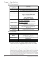
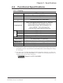
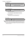
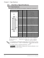
2.4
Part Names and Functions
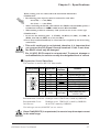
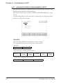
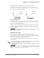
A:Display Panel
The GLC monitor screen displays the
screen setup and corresponding host (PLC)
data.
(All units)
B: Touch Panel
A,B
C
Front
(all units)
Performs any screen change operations and
sends data to the PLC.
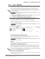
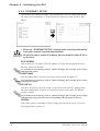
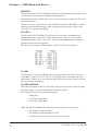
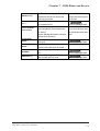
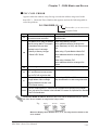
C: Status LED
Iindicates the GLC's current condition.
Color
Green
E
Red
D
Operation
Mode
Controller
Operation
Mode
ON
OFFLINE
ON
In operation
Flashing In operation
ON
In operation
--RUN
STOP
Major Error
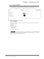
Indicator
F
Color
Indicator
Meaning
Orange
ON
Backlight burnout has occurred.
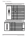
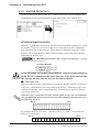
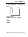
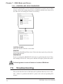
D: Expansion Unit I/F *1
Connects a data communication expansion
unit to the GLC. (currently disabled)
Rear
(GLC2400T)
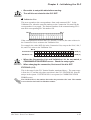
E: CF Card I/F
Insertion slot for CF Card.
F: CF Card Cover
Protects the CF Card interface and the CF Card
from contamination. When opened, the GLC
unit’s Dip Switches can be seen.
*1 Interface units for this interface are currently under development.
GLC2000 Series User Manual
2-9