1
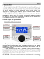
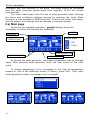
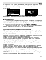
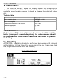
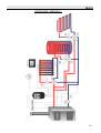
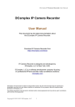
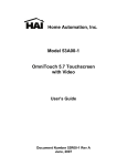
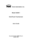
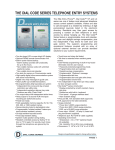
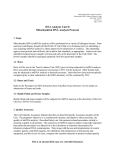
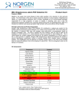
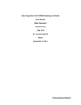
tech
-1-
ST-431 – user manual
Declaration of Conformity No. 42/2010
Hereby, we declare under sole responsibility that the ST-431
230V 50Hz thermoregulator manufactured by TECH, ul. St.
Batorego
14,
34-120
Andrychów,
is
compliant
with
the
Regulation by the Ministry of Economy. (Journal of Laws Dz.U.
155 Item 1089) of July 21, 2007 implementing provisions of
the Low Voltage Directive (LVD) 2006/95/EC of January 16,
2007.
The ST-431 controller has been tested for electromagnetic
compatibility (EMC) with optimal loads applied.
For compliance assessment, harmonized standards were
used:
PN-EN 60730-2-9:2006.
Paweł Jura, Janusz Master
-2-
tech
ATTENTION!
High voltage!
Make sure the regulator is disconnected from
the mains before working on the power
supply (cable connections, device
installation, etc.)!
All connection works must only be carried
out by qualified electricians.
Before activating the controller, measure the
motor resetting efficiency and inspect wire
insulation.
-3-
ST-431 – user manual
-4-
tech
I. Application
Thermoregulator type ST-431 is intended for operation of three- or
four-way mixing valve with a possibility of connecting additional valve
pump. Optionally, the controller may cooperate with two modules ST61, which enables to control altogether three mixing valves. The
controller is equipped with weather control function,1-week program
and may cooperate with the room regulator.
An additional advantage of the device is the protection of return
temperature, which fulfils the function of protection against boiling of
the water in the short boiler circulation or against too low temperature
of the water returning to the water boiler.
II. Principle of operation
Description of the control panel
PRESET
TEMPERATURE
VELVE
TEMPERATURE
STANDBY
MODE
(STANDBY)
OPENING
PERCENTAGE
EXIT
PULSE
GENERATOR
The principle of operation of the controller to valve servomotor is based
on mixing feed circulating warm water with water returning from the heating
circulation, in order to set the desired temperature and maintain it all the
time at the same level.
A pump connected to each valve is supposed to help to distribute water in
the system that is not based on gravitation circulation. The pump should be
installed behind the mixing valve, while the temperature sensor should be
placed behind the valve and the pump, for the purpose of the most accurate
control of the temperature at the valve outlet.
ATTENTION: if the valve controller operates simultaneously in a common
-5-
ST-431 – user manual
circulation with the controller of the boiler, the pump should be connected
from the boiler controller (pump outlet from regulator TS-431 will remain
disconnected).
The control takes place with the use of pulse generator knob. Entering
the menu and confirming settings proceed by pressing the knob. When
turning it, a user operates in MENU functions. To go to the higher level menu,
use exit button. Any settings may be changed in a similar manner.
II.a) Main page
During normal regulator operation , graphic display shows the
homepage, on which the following are displayed:
HOUR
WORKING
BOILER
PROTECTION
Valve type:
- CH
- Floor
PUMP OPERATION
ACTIVE MODULES
ACTIVE VALVE
By turning the pulse generator, the preset temperature may be changed
easily. After pressing pulse generator knob, the user moves to the main
menu.
To change appearance of the homepage to the view of temperature
sensors or one of the additional valves (if active), press EXIT. Then, after
choosing another screen, homepage view is changed.
-6-
tech
III. Main menu
III.a) Set temperature
With this option, the requested temperature the valve is supposed to
maintain, is set. In the course of correct operation, the temperature of water
behind the valve will be approaching the preset valve temperature.
III.b) Activated
This option is used to activate the mixing valve. When the valve is
deactivated, then the pump does not operate, either. In spite of the fact that
valve is deactivated, calibration always takes place after switching the
controller to the network. It prevents remaining of the valve in a position
dangerous (see chapter III.d) for the circulation.
III.c) Screen view
Using this function, appearance of the homepage may be changed
between the views of the basic valve, the view of the sensors' temperatures
or the view of parameters of one of additional valves (only when the valves
are active). After selecting the view sensors' temperatures, on the homepage
the following temperatures are visible: of the valve (set and current), return
temperature and external temperature. On the contrary, selection of the view
valve 1 or valve 2 results in displaying on the homepage parameters of the
closed valve: preset and current temperatures, external temperature and
return temperature, and the percentage of opening of the chosen valve.
III.d) Valve calibration
-7-
ST-431 – user manual
Using this function, initial setting of the valve is controlled. During
calibration, the valve is set to a safe position, that is, for CO valve, to a fully
open position, while for floor valve - to a closed position. During calibration, at
the bottom of the screen, the following symbol is displayed:
.
III.e) Manual operation
After selecting the option manual operation, the user has the possibility
of manually opening/closing the valve (and additional valves, if active) and
switching on or off the pump for the purpose of inspection of the correct
operation of the device.
III.f) Installer menu
Functions included in installer menu will be described in detail in
subsequent chapters of this manual.
III.g) Servicing menu
Functions included in the servicing menu are protected by code and are
not available for the user.
III.h) Language selection
A user can select the language version of the controller.
-8-
tech
III.i) Factory settings
The regulator is pre-configured for operation. However, it should be
adjusted for own needs. Return to the factory settings is possible at any
moment. By activating the factory settings option, all own adjustments are
replaced by the settings saved by the manufacturer. From that moment, the
own parameters may be set once again.
III.j) About the program
After activating this option, the display shows the boiler manufacturer's
logo along with software version of the regulator.
IV. Installer menu
IV.a) Summer mode
In this mode the regulator closes CO valve, so as not to heat house
unnecessarily, but in the case of achieving, too high temperature of the boiler
(requires activation of the return protection!) the valve will be open in
emergency mode. This mode is not active in the case of controlling floor
valve.
IV.b) Pump anti-stop
After activating this option, pump valve will activate every 10 days for
2 minutes. It prevents too long water stagnation in the assembly beyond the
heating season.
-9-
ST-431 – user manual
IV.c) Boiler sensor
In this submenu, the user determines basic boiler protection parameters
and pump activation.
IV.c.1) Return protection
This function permits setting the boiler protection against too cool water
returning from the main circulation, which could cause low-temperature boiler
corrosion. The return protection operates in the way that when the
temperature is too low, valve is closed, until the short circulation of the boiler
reaches the appropriate temperature. After activating it, user presets the
minimum acceptable return temperature.
IV.c.2) Boiler protection
The protection against too high return temperature serves to prevent
the hazardous growth in boiler temperature. The user sets the maximum
acceptable return temperature. In the case of the hazardous growth in
temperature, the valve begins to open to house installation in order to cool
the boiler down. This function is activated permanently (the possibility of
deactivation only in the service menu).
IV.c.3) Pump activation
This option allows to select the working mode of a pump. A pump shall
be activated: always (pump operates all the time, regardless of
temperatures), never (pump is permanently deactivated and the regulator
controls only operation of the valve, above the threshold (the pump is
activated above the set activation temperature ). In the case when the
circulation pump is connected with the boiler controller, it is recommended to
- 10 -
tech
deactivate its operation in the driver of valve ST-431.
IV.d) Temperature control
This parameter determines water temperature measurement (control)
frequency behind the CH or HWT installation valve. If the sensor indicates a
change in temperature (deviation from the set value), then the electric valve
will open or close by the set stroke, in order to return to the preset
temperature.
IV.e) Reduction in room control
This function is active only in the case when the valve cooperates with
the room regulator. In this setting, one should preset the temperature by
which the valve decreases its preset temperature, at the moment of achieving
the preset temperature at the room regulator (room heat-up).
NOTE: If in function Room regulator (see IV.e) option Closing is set, then
function Reduction in room control is inactive.
IV.f) Room regulator
This option is used to set the manner in which the valve will react to a
signal about room heat-up (from the room regulator). If option Reduction in
room control is selected, then the valve, after a signal about heating-up (from
the regulator room) will lower temperature behind the valve – according to
the set parameter Reduction in room control (see IV.e). In the event when
option Closing is selected, the valve will react to the signal about heat-up
room with maximum closing (see item IV.m) and deactivation of the pump.
IV.g) Proportionality coefficient
- 11 -
ST-431 – user manual
Proportionality coefficient is used for defining valve stroke. The closer
the preset temperature, the smaller the stroke. If this coefficient is high, the
valve will faster achieve the opening close to the relevant. However, the
opening will not be accurate. Single opening percentage is calculated on the
basis of a formula:
(SET_TEMP - SENSOR_TEMP) * (PROP_COEFF /10)
IV.h) Maximum floor temperature
This is the maximum temperature, which does not damage floor
installation. Setting this temperature is used, when valve type is set as the
floor type. After reaching this temperature, a complete valve closure takes
place, and a user is informed about that by means of a relevant alarm. If the
maximum floor temperature is reached, the boiler protection function is
deactivated. In this case, the floor installation protection will have a higher
priority.
IV.i) Opening direction
If after connection of the valve to the controller it turns out that it was
to be connected the other way round, then the power supply cables do not
have to be switched, it is enough change the opening direction in this
parameter.
LEFT *
RIGHT *
IV.j) Operation modes
In this function, user selects the working mode between:
STANDARD - the controller maintains the preset temperature at the valve
exit level.
ROOM CONTROL - the controller maintains the temperature of the valve till
the moment in which room the regulator gives the signal about heating-up of
the room (contact opening). Then the preset temperature will be reduced by
the temperature value set for parameter REDUCTION IN ROOM CONTROL
- 12 -
tech
(see chapter: IV.e). The reduced preset temperature will not be displayed on
the main screen of the controller. The information that the room regulator
indicated that the room is heated up is signalled by room regulator
symbol<p>(continuous display, not pulsating).
WEATHER CONTROL - the preset valve temperature depends on the
temperature outside. It is calculated on the basis of parameters saved in
functions Weather-based control (see chapter IV.s).
ROOM AND WEATHER CONTROL – in this mode, when the room regulator
does not reach the set temperature, valve operates just as in weather control.
At the time when the room is heated up to the set temperature of the
regulator , the valve starts to operate in mode room control (at achieved
room control). While this mode is active, on the display the symbols of
weather control and room control pulsate alternately. After reaching the
temperature preset by the controller, the symbol<p>(room regulator heated
up) will be displayed permanently.
WEEKLY CONTROL - the preset valve temperature depends on the
deviations defined for particular weekdays in Chapter Weekly control (see
item IV.t). In this mode room control or weather control are disabled. The
information on active weekly control is pulsating on the main screen value of
the current temperature deviation (at the place of text "preset").
IV.k) Opening time
Parameter specifying the time needed for the servomotor valve to open
from 0% to 100% position. This time should be selected according to the
owned valve servomotor (stated on the rating plate).
IV.l) Unit step
This is a maximum single stroke (opening or closing) that the valve may
make during one temperature sampling. If it is near the preset temperature,
the stroke calculated on the basis of WSP PROPORCJON parameter position.
The smaller the single stroke, the more precisely the set temperature can be
achieved. However, the preset temperature is being fixed for a longer time.
- 13 -
ST-431 – user manual
IV.m) Minimum opening
The parameter determines, which valve opening may be the smallest
Thanks to that parameter, the valve may be opened minimally, to maintain
the smallest flow.
IV.n) Valve type
By means of this setting, the user selects the type of the controlled
valve between:
CH - it is set to adjust CH circulation temperature.
FLOOR - it is set to adjust floor heating circulation temperature. Floor
type protects the installation from dangerous temperatures. If the valve
type is set as CH and it will be connected to floor system, this may
result in the destruction of fragile floor installation.
IV.o) Valve 1
NOTE
Controlling additional valve is possible after purchasing and connecting to the
controller control module ST-61, which is not provided in the standard version
of the controller. To control two valves two modules ST-61 should be
connected.
This option is used to set operation
valve. To make sure that the valve works
expectation, is should be registered by
number of the valve in accordance with
parameters should be set.
of an additional module of the mixing
properly in accordance with the user's
entering the module number (this is
the documentation) and then several
1. Activated
So that the selected valve would be active, select option >
Activated> Yes. When it is necessary to deactivate the valve for some time,
the user selects: Activated>> No.
- 14 -
tech
2. Temperature control
This parameter determines the sampling (control) frequency of the
water temperature behind the valve for the CH or the HUW system. If the
sensor indicates a change in temperature (deviation from the set value), then
the electric valve will open or close by the set stroke in order to return to the
set temperature.
3. Opening time
In this function the time of full opening of the valve is set, in other
words, time in which the valve is open to the value of 100%. This time should
be selected according to the owned valve servomotor (stated on the rating
plate).
4. Unit step
In this function, per cent unit stroke of valve opening is set, namely
which maximum opening or closing percent may each time be performed by
the mixing valve (maximum valve movement in one measurement cycle).
5. Minimum opening
In this function, the minimum value of the valve opening is set. Below
this value, the mixing valve will not close any further.
6. Valve type
With the use of this option, the user selects the type of the valve: CH or
floor.
7. Weather-based control
By means of this parameter, it is possible to adjust the temperature set
for valve 1, for respective values of external temperatures. On the basis of
agreed points, values for intermediate points are calculated.
TEMP.
TEMP.
TEMP.
TEMP.
FOR
FOR
FOR
FOR
-20
-10
0
10
A detailed description of this function is included in Chapter IV.s).
8. Return protection
This function permits setting the boiler protection against too cool water
returning from the main circulation, which could cause low-temperature boiler
corrosion. The return protection operates in the way that when the
temperature is too low, valve is closed, until the short circulation of the boiler
reaches the appropriate temperature. This function protects also the boiler
against dangerously high temperature of return in order to prevent boiling of
water.
After enabling this function, the user sets the minimum and maximum
acceptable temperature of return:
9. Additional sensors
After selecting this function, the user has the possibility of selecting
sensors from which the data on temperatures for the valve will be collected.
Temperatures can be collected from module sensors (own) or according to the
- 15 -
ST-431 – user manual
sensors of the main controller.
10. Valve removal
This function is used for a complete removal of the valve from the
controller memory. Valve removal is used e.g. at disassembling the valve or
module replacement (re-registration of a new module is necessary).
IV.p) Valve 2
If the user wants to control the second optional valve, they should, like
in the previous case, register valve 2 (additional) and configure adequately all
settings in the same manner as in the case of valve 1.
IV.r) Communication mode
The user may set the communication mode as main (independent) or
subordinate (in cooperation with the with primary controller mounted on the
boiler). If the communication mode is selected as subordinate, the valve
controller operates as a module and all its settings are made from the boiler
controller.
IV.s) Weather-based control
By means of this parameter, it is possible to adjust the set valve
temperature for relevant values of external temperatures. On the basis of
agreed points, values for intermediate points are calculated.
TEMP.
TEMP.
TEMP.
TEMP.
FOR
FOR
FOR
FOR
-20
-10
0
10
Heating curve – it is a curve, according to which the set controller
temperature is determined, on the basis of external temperature. In our
controller, this curve, is constructed on the basis of four points of set
temperatures for respective values of external temperatures. Set
temperatures must be determined for external temperatures - 20ºC, - 10ºC,
- 16 -
tech
0ºC and 10ºC.
The more points constructing the curve, the greater its accuracy, which
allows its flexible shaping. In our case, four points seem a very good
compromise for large accuracy and for easiness of setting of the course of this
curve.
Where, in our controller:
XA = -20ºC,
XB = -10ºC,
XC = 0ºC,
XD = 10ºC,
YA, YB, YC, YD – preset valve temperatures for respective external
temperatures: XA, XB, XC, XD
IV.t) Weekly control
This function is used for programming daily temperature changes behind
the valve. The set temperature deviations are in the range of +/-10 0 C.
Step one:
A user must first set the current time and date (Installer menu> Timer).
Step two:
The user sets temperatures for particular weekdays (Set mode 1):
Monday – Sunday
- 17 -
ST-431 – user manual
In this mode, specific hours and the requested deviations from the
preset temperature should be marked (by how many degrees the
temperature is supposed to raise or drop in a given hour) for each day of
the week. Additionally, to facilitate the service, there is a possibility to
copy the settings.
Example
Monday
set: 300 AM, TEMP -100 C (temperature change – 100 C)
set: 400 AM, TEMP -100 C (temperature change – 100 C)
set: 500 AM, TEMP -100 C (temperature change – 100 C)
In this case, if the set valve temperature is 60 0 C, on Monday from 300 to
600, the preset valve temperature shall drop by 10 0 C, so it will be 500 C.
Instead of setting the temperatures for different days, the temperatures in
the second mode may be set collectively for working days (Monday to Friday)
and weekend (Saturday and Sunday) – Set mode 2.
Monday – Friday; Saturday – Sunday
In this mode, like in the previous one, specific hours and requested
deviations from the temperature preset for business days (MondayFriday) and on weekend (Saturday, Sunday) should be indicated.
Example
Monday-Friday
set: 300 AM, TEMP -100 C (temperature change – 100 C)
set: 400 AM, TEMP -100 C (temperature change – 100 C)
set: 500 AM, TEMP -100 C (temperature change – 100 C)
Saturday-Sunday
set: 4 00 PM, temperature 5 0 C (temperature change + 5 0 C)
set: 500 PM, temperature 5 0 C (temperature change + 50 C)
set: 600 PM, temperature 5 0 C (temperature change + 50 C)
In this case, if the temperature preset in the boiler is 60 0 C, than from
3 00 a.m. to 6 00 a.m. every day, from Monday to Friday, the preset
temperature of the valve will drop by 10 0 C, namely it will be 50 0 C.
In turn, during weekend (Saturday, Sunday) from 4 00 p.m.to 7 .00 p.m,
the preset temperature of the valve will increase by 5 0 C namely it will
be 65 0 C.
Step three (Mode):
A user activates one of the two previously set modes (Mode1, Mode2),
or deactivates the weekly control option completely.
After activating one of the modes, on the controller homepage, in the place
- 18 -
tech
of preset text (the preset temperature), the digit with the value of the
currently preset deviation shall be pulsating (informing at the same time
about the weekly control activity).
IV.u) Timer
By setting the timer, a user defines the current time and weekday. Without
setting the time, correct operation of the weekly control is not possible.
VI. Protections
To ensure the maximally safe and reliable operation , the regulator
has several protections. In the case of alarm, a sound signal is activated
and a relevant message is shown on the display.
To make the controller return to work, press pulse generator.
In the alarm, manual work is possible, but it should be completely
ensured whether our activities will not result in damages.
The controller has the following alarm protections:
1. Temperature alarm - stops the valve temperature regulation and sets the
valve in the safest position. For floor valve - it is closing, and for CH valve it is
opening.
2. Alarm - VALVE SENSOR - means an incorrect connection or lack of
connection of the valve sensor or its damage. It is a sensor strategic for valve
operation, therefore it should be replaced immediately.
3. Alarm - RETURN SENSOR – alarm occurs, when the return protection
function is activated and the damage of this sensor takes place. The return
sensor should be then corrected or replaced.
There is a possibility of deactivating this alarm by switching off the return
protection function, but if a circulation does not have the protection against
boiling of water at the boiler, it may cause a permanent damage of the boiler
or a part of circulation.
4. Alarm - WEATHER SENSOR - occurs, when external temperature sensor is
damaged. The alarm may be cancelled, when an undamaged sensor is
installed correctly. The alarm shall be activated, when valve operation mode is
different than "weather control " or "room control with weather control".
The regulator is equipped with WT 1.6A tubular fuse cartridge,
protecting the network.
ATTENTION: The fuse of higher value should not be used. Assembling the
fuse with a higher value may cause damage to the controller.
- 19 -
ST-431 – user manual
V. Maintenance
In controller TS-431, before the heating season and throughout its
duration, technical condition of wires should be checked. Fastening of the
controller should be also checked, it should be cleaned from dust and other
dirt.
Technical data
Temperature control range
8oC : 90oC
Power supply voltage
230V/50Hz +/- 10%
Power consumption
max. 4W
Temperature endurance of the sensors
-25oC : 95oC
Ambient temperature
5oC : 50oC
Load at each outlet
0,5A
Fuse insert
1,6A
! ATTENTION !
In the case of the lack of flow in the short circulation of the
boiler (improperly mounted system), the return sensor should
be placed at the outlet of hot water from the boiler, to prevent
its boiling.
VI. Mounting
ATTENTION: Installation should be performed by a person with relevant
authorizations! At that time, the device cannot be live (make sure that
the plug is disconnected from the network)!
Connection of wires
- 20 -
tech
Schematic diagram
- 21 -
ST-431 – user manual
Contents
I. Application.........................................................................................5
II. Principle of operation..........................................................................5
II. a) Main page..................................................................................6
III. Main menu....................................................................................... 7
III. a) Set temperature........................................................................7
III. b) Activated..................................................................................7
III. c) Screen view..............................................................................7
III. d) Valve calibration........................................................................7
III. e) Manual operation.......................................................................8
III. f) Installer menu............................................................................8
III. g) Servicing menu.........................................................................8
III. h) Language selection....................................................................8
III. i) Factory settings..........................................................................9
III. j) About the program.....................................................................9
IV. Installer menu.................................................................................... 9
IV. a) Summer mode...........................................................................9
IV. b) Pump anti-stop..........................................................................9
IV. c) Boiler sensor............................................................................10
IV. c.1) Return protection................................................................10
IV. c.2) Boiler protection..................................................................10
IV. c.3) Pump activation..................................................................10
IV. d) Temperature control.................................................................11
IV. e) Reduction in room control..........................................................11
IV. f) Room regulator.........................................................................11
IV. g) Proportionality coefficient...........................................................11
IV. h) Maximum floor temperature.......................................................12
IV. i) Opening direction......................................................................12
IV. j) Operation modes.......................................................................12
IV. k) Opening time...........................................................................13
IV. l) Unit step..................................................................................13
IV. m) Minimum opening....................................................................13
IV. n) Valve type...............................................................................14
IV. o) Valve 1...................................................................................14
IV. p) Valve 2...................................................................................16
IV. r) Communication mode................................................................16
IV. s) Weather-based control..............................................................16
IV. t) Weekly control..........................................................................17
IV. u) Timer......................................................................................19
VI. Protections...................................................................................... 19
VII. Maintenance................................................................................... 20
VIII. Mounting...................................................................................... 20
- 22 -
tech
- 23 -
tech
- 24 -