1
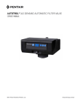
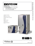
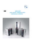
User’s Manual Can Open DSP402 attachment INDEX 1. INTRODUCTION .......................................................................................................... 2 1.1 1.2 1.3 1.4 2. ABOUT THIS MANUAL ..................................................................................................................... 2 COMMON SYMBOLS AND ABBREVIATIONS ................................................................................. 2 INTENDED AUDIENCE ..................................................................................................................... 2 UNIT MEASURING SYSTEM ............................................................................................................ 2 CAN OPEN DSP402 PROFILES .................................................................................. 3 2.1 2.2 CAN OPEN DS402 PROFILES SUPPORTED.................................................................................. 3 DEVICE CONTROL ........................................................................................................................... 3 2.2.1 2.3 2.4 2.5 2.6 2.6.1 2.6.2 2.7 2.8 2.9 2.10 SECOND SENSOR .................................................................................................................................. 4 PROFILE VELOCITY MODE ............................................................................................................. 5 PROFILE POSITION MODE ............................................................................................................. 6 INTERPOLATE POSITION MODE .................................................................................................... 7 HOMING MODE ................................................................................................................................ 8 HOMING SWITCHES ............................................................................................................................... 9 HOMING WITH TOUCH PROBE .............................................................................................................. 9 PROFILE SYNC VELOCITY MODE ................................................................................................. 11 PROFILE SYNC POSITION MODE ................................................................................................ 12 OTHER MAPPED OBJECTS .......................................................................................................... 13 ALARMS ...................................................................................................................................... 14 MB00201E00 V_1.2 1 FIRMWARE VERSIONS: 12.0 / 22.0 1. INTRODUCTION 1.1 ABOUT THIS MANUAL This manual is meant as a brief explanation of OPDE CAN OPEN DSP402. The manual contains the following chapters: 1.2 1.3 Revision Table contains the history revision of the manual; Introduction provides information background about the manual; CAN OPEN DSP402 Profiles contains the DSP402 Profiles cabling instruction and general information about EtherCAT connections; COMMON SYMBOLS AND ABBREVIATIONS Abbreviations Explanations CAN Controller Area Network CiA CAN in Automation EMCY Emergency Object or Service OPDE Open Drive Exp or OPDExp OPD Explorer OPD Explorer Supervisory Software SDO Service Data Object INTENDED AUDIENCE The manual is intended for those persons who are responsible for commissioning and using an OPDE CAN Module. The reader should have some basic knowledge of networking, electrical fundamentals, electrical wiring practices and how to work the OPDE drive and OPD Explorer. 1.4 UNIT MEASURING SYSTEM The units of measurement used by CAN Open DSP 402 are the following: o o o 2 Positions are expressed in “ie” (encoder pulse). One mechanical motor revolution is 65536 ie (or encoder pulses); Speed are expressed in “ie/s”. One revolutions-per-second is 65536 ie/s; Accelerations are expressed in “ie/s2”. One revolutions-per-second2 is 65536 ie/s2 MB00201E00 V_1.2 2. CAN OPEN DSP402 PROFILES 2.1 CAN OPEN DS402 PROFILES SUPPORTED In OPDE drive are implemented the following CAN Open DSP 402 profiles: - Device Control; - Profile Velocity Mode; - Profile Position Mode; - Interpolation Position Mode; - Homing Mode; - Cyclic synchronous velocity mode; - Cyclic synchronous position mode. For more information, see CiA Draft Standard Proposal 402 specifications. 2.2 DEVICE CONTROL Device controls is a profile that define the behaviour of the control device. The master controls like the slave works with the following objects: Control Word; Status word; Modes of operation; Modes of operation display; Quick stop option code; - Quick stop deceleration; The object descriptions are in Tab. 1: Index (hex) Obje ct Type Name 6040 VAR UNSIGNED16 Control word 6041 VAR UNSIGNED16 Status word Description This object controls Machine of DSP 402. the Finite PDO Mapping Access Yes Reading/ writing Yes reading Yes Reading /writing Yes reading State OPD Explorer Parameter: E100 This object provides the status of Finite State Machine of DSP 402. OPD Explorer Parameter: D64 This object indicates the requested operation modes. OPDE drive supports the following modes: 6060 6061 VAR VAR MB00201E00 V_1.2 INTEGER8 INTEGER8 Modes of operation Modes of operation display 1. 3. 6. 7. 8. 9. Profile position mode; Profile velocity mode; Homing mode; Interpolation position mode; Cyclicsync position mode; Cyclic sync velocity mode. OPD Explorer Parameter: E01 This object provides the actual operation mode OPD Explorer Parameter: D65 3 This object indicates what action is performed when the quick stop function is executed. OPDE drive supports the following codes: 605A VAR INTEGER16 Quick stop option code Slow down on quick stop ramp and transit into Switch On Disabled; Slow down on quick stop ramp and stay in Quick Stop Active; No Reading Yes Reading Note: if the inserted code is not expected, the quick stop option code executes the code 1. 6085 VAR UNSIGNED32 Quick stop decelerat ion OPD Explorer Parameter: E38 This object configures the deceleration used to stop the motor when the quick stop function is activated. OPD Explorer Parameters: E08-E09 Tab. 1- Device Control Objects 2.2.1 SECOND SENSOR The parameter E51, pENSECONDSENS = Yes allows to select the second sensor and close the position loop on this. There is the possibility to set a gear ratio between motor revolution and driving shaft revolution parameters E60-E61 pNUM_GEAR_BOX, and parameters E62-E63 - pDEN_GEAR_BOX). Tab. 2 shows second sensor function parameters. Name Value UM Default Min Max pENSECONDSENS No pNUM_GEAR_BOX 1 Rev 1 1 2147483647 pDEN_GEAR_BOX 1 Rev 1 1 2147483647 pENMULTICORRECT No No Description E51 – Enable second sensor No E60-E61– Gear box numerator E62-E63 – Gear box numerator E64 Enable correction for absolute multi-turn sensor Tab. 2- Second sensor device control Fig. 1-Second sensor graphic interface The example shown in Fig. 1 regards a system with a reduction ratio 10:1 between the motor shaft and the driving shaft, with a revolution of the driving shaft. The second sensor is an encoder with 4096 pulses/revolution set in the parameter P17-ENC2_PPR. This parameter is located in the directory: All Parameters > Application I/O Parameters > Input > Second Sensor 4 MB00201E00 V_1.2 The internal software realizes a possible “correction” for incremental sensor’s which have zero pulse. In these kind of sensor when comes the zero pulse signal the position goes to zero. For the homing method’s without index pulses (metods 17---30) take place the correction when the zero pulse comes and the position doesn’t go to zero. The “correction” is allowed for both sensors (first or second). If the second sensor is enabled, the value of position, velocity and acceleration in all the operation mode available al referred to the motor shaft side. For example if the gear ratio is 10:1 (1 turn of the motor shaft = 10 turns of the driving shaft) and the position target pTARGETPOS – E10 – E11 is 655360 i.e., the motor turns for 10 revolutions and the driving shaft for 1 revolution. For each PWM period a pulses difference is calculated (delta pulses), depending on the second sensor mechanical position read. This value is reported to motor side by relationship: pNUM_GEAR_BOX E60-E61 · pDEN_GEAR_BOX E62-E63 motor side delta pulses = · · delta pulses sec. Sensor The parameter E64- pENMULTICORRECT (if enabled) consent to correct the overflow for absolute sensor multi-turn when the high mechanical position (number of turns) reach the maximum number of turn. For example for ENDAT-BISS 12bit after 4095 turns high position goes to zero value, this could be a problem. 2.3 PROFILE VELOCITY MODE The profile velocity mode covers the following sub-functions: Demand value input via trajectory generator; Velocity capture using position sensor or velocity sensor; Velocity control function with appropriate input and output signals; Monitoring of the profile velocity using a window-function; Monitoring of velocity actual value using a threshold. OPDE drive supports the following Profile Velocity Mode objects (Tab. 3): Index (hex) 606C 606D 606E Object VAR VAR VAR Type Name INTEGER32 Velocity actual value UNSIGNED16 UNSIGNED16 Velocity window Velocity window time UNSIGNED32 606F 6070 6083 VAR VAR VAR MB00201E00 V_1.2 UNSIGNED16 ** UNSIGNED16 UNSIGNED32 Velocity threshold Velocity threshold time Profile accelerati on Description PDO Mapping Access Yes Reading Yes Reading/ writing Yes Reading/ writing Yes Reading/ writing Yes Reading/ writing Yes Reading/ writing This object provides the actual velocity. OPD Explorer Parameters: D68D69 This object indicates the configured velocity window. OPD Explorer Parameter: E22 – E23 This object indicates the configured velocity window time. OPD Explorer Parameter: E24 This object indicates the configured velocity threshold. OPD Explorer Parameter: E18-E19 This object indicates the configured velocity threshold time. OPD Explorer Parameter: E20 This object indicates the configured acceleration. OPD Explorer Parameter: E04-E05 5 6084 60FF VAR VAR UNSIGNED32 Profile decelerat ion Target velocity INTEGER32 This object indicates configured deceleration the OPD Explorer Parameter: E06-E07 This object indicates the configured target velocity. Yes Reading/ writing Yes Reading/ writing OPD Explorer Parameter: E02-E03 Tab. 3- Profile Velocity Mode Objects 2.4 PROFILE POSITION MODE In profile position mode a target position is applied to the trajectory generator. The trajectory generator produces a position demand value for the position control loop. OPDE drive supports the following Profile Position Mode objects (Tab. 4): Index (hex) 6064 6065 6067 606F 607A Object VAR VAR VAR VAR VAR Type Name INTEGER 32 Position actual value UNSIGNED 32 Following error window UNSIGNED 32 UNSIGNED 16 INTEGER32 Position window Velocity threshold Target position Description PDO Mapping Access This object provides the actual position. Yes Reading OPD Explorer Parameters: D66D67 This object indicates the configured range of tolerant position values symmetrically to the position demand value. Yes Reading/writing OPD Explorer Parameters: E16 – E17 This object indicates the configured symmetrical range of accepted positions relative to the target position. Yes Reading/writing Yes Reading/writing Yes Reading/writing No Reading Yes Reading/writing OPD Explorer Parameter: E14E15 This object indicates the configured velocity threshold. OPD Explorer Parameter: E18E19 This object indicates the commanded position that the drive should move to in position profile mode. OPD Explorer Parameter: E10E11 607D 6 UNSIGNED 8 Highest subindex supported (Sub-index 0) INTEGER 32 Min position limit (Sub-index 1) ARRAY Highest sub-index supported This object indicates the maximal software position limit. OPD Explorer Parameter: E40– E41 MB00201E00 V_1.2 6081 VAR 6083 VAR 6084 VAR INTEGER 32 Max position limit (Sub-index 2) UNSIGNED 32 Profile velocity UNSIGNED 32 Profile acceleration UNSIGNED 32 Profile deceleration This object indicates the maximal software position limit. OPD Explorer Parameter: E42E43 This object indicates the configured velocity normally attained at the end of the acceleration ramp during a profiled motion. Yes Reading/writing Yes Reading/writing Yes Reading/writing Yes Reading/writing OPD Explorer Parameter: E12E13 This object indicates the configured acceleration. OPD Explorer Parameter: E04E05 This object indicates the configured deceleration OPD Explorer Parameter: E06E07 Tab. 4 - Profile Position Mode Objects 2.5 INTERPOLATE POSITION MODE Interpolated position mode is used to control multiple coordinated axes or a single axis with the need for timeinterpolation of set-point data. The interpolated position mode normally uses time synchronisation mechanisms for a time coordination of the related drive units (e.g. Distributed Clock in EtherCAT protocol). OPDE drive supports the following Interpolated Position Mode objects (Tab. 5): Index (hex) 6064 606F 60C1 Object VAR VAR Type Name INTEGER 32 Position actual value UNSIGNED 16 Velocity threshold UNSIGNED 8 Highest sub-index supported (Sub-index 0) INTEGER 32 Interpolate d data – 1st set-point (Subindex 1) ARRAY Description PDO Mapping Access Yes Reading Yes Reading/writing No Reading Yes Reading/writing This object provides the actual position. OPD Explorer Parameters: D66D67 This object indicates the configured velocity threshold. OPD Explorer Parameter: E18E19 Highest sub-index supported This object indicates data words, which are necessary to perform the interpolation algorithm. OPD Explorer Parameter: E24E25 Tab. 5 - Interpolated Position Mode Objects MB00201E00 V_1.2 7 2.6 HOMING MODE Homing Mode implements the methods which a drive seeks the home position, or initial reference point (also called, the datum or zero point). There are various methods of achieving this using limit switches at the ends of travel or a home switch (zero point switch) in mid-travel, most of the methods also use the index (zero) pulse train from an incremental encoder. OPDE drive supports the following methods: 1. Homing on negative limit switch and index pulse; 2. Homing on positive limit switch and index pulse; 3. Homing on positive home switch and index pulse. The home position is at the left of the point where the home switch changes state; 4. Homing on positive home switch and index pulse. The home position is at the right of the point where the home switch changes state; 5. Homing on negative home switch and index pulse. The home position is at the right of the point where the home switch changes state; 6. Homing on negative home switch and index pulse. The home position is at the left of the point where the home switch changes state; 7. Homing on home switch and index pulse with positive limit switch. The home position is at the left of the point where the home switch has falling edge; 8. Homing on home switch and index pulse with positive limit switch. The home position is at the right of the point where the home switch has rising edge; 9. Homing on home switch and index pulse with positive limit switch. The home position is at the left of the point where the home switch has rising edge; 10. Homing on home switch and index pulse with positive limit switch. The home position is at the right of the point where the home switch has falling edge; 11. Homing on home switch and index pulse with negative limit switch. The home position is at the right of the point where the home switch has falling edge; 12. Homing on home switch and index pulse with negative limit switch. The home position is at the left of the point where the home switch has rising edge; 13. Homing on home switch and index pulse with negative limit switch. The home position is at the right of the point where the home switch has rising edge; 14. Homing on home switch and index pulse with negative limit switch. The home position is at the left of the point where the home switch has falling edge; 17. Homing on negative limit switch without index pulse; 18. Homing on positive limit switch without index pulse; 19. Homing on positive home switch without index pulse. The home position is at the left of the point where the home switch changes state; 21. Homing on negative home switch without index pulse. The home position is at the right of the point where the home switch changes state; 23. Homing on home switch and index pulse without positive limit switch. The home position is at the left of the point where the home switch has falling edge; 26. Homing on home switch without index pulse with positive limit switch. The home position is at the right of the point where the home switch has falling edge; 27. Homing on home switch without index pulse with negative limit switch. The home position is at the right of the point where the home switch has falling edge; 30. Homing on home switch without index pulse with negative limit switch. The home position is at the left of the point where the home switch has falling edge; 33. Homing on index pulse. The home position is at first index pulse found on the left; 34. Homing on index pulse. The home position is at first index pulse found on the right; 35. Homing on index pulse. The home position is the current position. 8 MB00201E00 V_1.2 OPDE drive supports the following Homing Mode objects ( Tab. 6). Index (hex) Object Type UNSIGNED 16 Name Velocity threshold 606F VAR 607C VAR INTEGER 32 Home offset 6098 VAR INTEGER 8 Homing method UNSIGNED 8 6099 ARRAY UNSIGNED 32 UNSIGNED 32 609A VAR UNSIGNED 32 Highest sub-index supported (Sub-index 0) Speed during search for switch (Subindex 1) Speed during search for zero (Subindex 2) Homing acceleratio n PDO Mapping Access Yes Reading/writing Yes Reading/writing Yes Reading/writing Highest sub-index supported No Reading This object indicates the configured speed during search for switch. OPD Explorer Parameter: E30E31 Yes Reading/writing This object indicates the configured speed during search for zero. OPD Explorer Parameter: E32E33 Yes Reading/writing This object indicates the configured acceleration and deceleration to be used during homing operation. OPD Explorer Parameters: E34E35 Yes Reading/writing Description This object indicates the configured velocity threshold. OPD Explorer Parameter: E18E19 This object indicates the configured difference between the zero position for the application and the machine home position. OPD Explorer Parameters: E28E29 This object indicates the configured homing method The supported methods are those descripted above. OPD Explorer Parameters: E26 Tab. 6 - Homing Mode Objects 2.6.1 HOMING SWITCHES The homing switches are implemented with the following Logic Input Functions: positive limit switch is the input logic function I28; negative limit switch is the input logic function I29; home switch is the input logic function I30. For more information about input logic functions, see OPDE manual. 2.6.2 HOMING WITH TOUCH PROBE In this method, the position is not sampled by control device, but by the drive device itself. When the switch is triggered, the corresponding actual position together will the switch signal shall be reported. MB00201E00 V_1.2 9 Index (hex) Obje ct Type 60B8 VAR UNSIGNED 16 60B9 VAR UNSIGNED 16 60BA VAR INTEGER 32 Touch probe pos1 pos value 60BB VAR INTEGER 32 Touch probe pos1 negative value VAR INTEGER 32 Touch probe pos2 positive value VAR INTEGER 32 Touch probe pos2 negative value 60BC 60BD Name Description Touch probe function Touch probe status This object indicates the configured function of touch probe. OPD Explorer Parameter: E104 This object indicates the status of touch probe. OPD Explorer Parameters: E105 This object indicates the position values of touch probe 1 at positive edge. The value shall be given in user-defined position units. OPD Explorer Parameters: E106E107 This object indicates the position values of touch probe 1 at negative edge. The value shall be given in user-defined position units. OPD Explorer Parameters: E108E109 This object indicates the position values of touch probe 2 at positive edge. The value shall be given in user-defined position units. OPD Explorer Parameters: E110E111 This object indicates the position values of touch probe 2 at positive edge. The value shall be given in user-defined position units. OPD Explorer Parameters: E112E113 PDO Mapping Access Yes Reading/writi ng Yes Reading Yes Reading Yes Reading Yes Reading Yes Reading Tab. 7- Touch probe objects For touch probe function, the setting is: bit value definition 0 Switch off touch probe 1 1 Enable touch probe 1 0 Trigger first event 1 continuous 0 Trigger with touch probe 1 input 1 Trigger with zero impulse signal or position encoder 0 1 2 3 0 Reserved 0 Switch off sampling at positive edge of touch probe 1 1 Enable sampling at positive edge of touch probe 1 0 Switch off sampling at negative edge of touch probe 1 1 Enable sampling at negative edge of touch probe 1 - User-defined 0 Switch off touch probe 2 1 Enable touch probe 2 0 Trigger first event 1 continuous 0 Trigger with touch probe 2 input 4 5 6,7 8 9 10 10 MB00201E00 V_1.2 11 1 Trigger with zero impulse signal or position encoder 0 Reserved 0 Switch off sampling at positive edge of touch probe 2 1 Enable sampling at positive edge of touch probe 2 0 Switch off sampling at negative edge of touch probe 2 1 Enable sampling at negative edge of touch probe 2 - User-defined 12 13 14,15 Tab. 8- Touch probe function bits And for touch probe status: bit value definition 0 Touch probe 1 is switched off 1 Touch probe 1 is enabled 0 Touch probe 1 no positive edge value stored 1 Touch probe 1 positive edge value stored 0 Touch probe 1 no negative edge value stored 1 Touch probe 1 negative edge value stored 0 Reserved 0 1 2 3 to 5 6,7 - User-defined (e.g. for testing) 0 Touch probe 2 is Switched off 1 Touch probe 2 is Enabled 0 Touch probe 2 no positive edge value stored 1 Touch probe 2 positive edge value stored 0 Touch probe 2 no negative edge value stored 1 Touch probe 2 negative edge value stored 11 to 13 - Reserved 14, 15 - User-defined (e.g. for testing) 8 9 10 Tab. 9- Touch probe status bits 2.7 PROFILE SYNC VELOCITY MODE The cyclic synchronous velocity mode covers the following sub-functions: Demand value input Velocity capture using position sensor or velocity sensor Velocity control function with appropriate input and output signals Limitation of torque demand Various sensors may be used for velocity capture. In particular, the aim is that costs are reduced and the drive power system is simplified by evaluating position and velocity using a common sensor, such as is optional using a resolver or an encoder. The behavior of the control function is influenced by control parameters such as limit functions, which are externally applicable. The drive internal control function is not specified more precisely in this part of profile specification as it is highly manufacturer-specific, but the format and content of the control parameters are provided. The input (from the control device point of view) are the target velocity. The drive device may support limitation of motor speed and a quick stop function for emergency reasons. The interpolation time period defines the time period between two updates of the target velocity and shall be used for intercycle interpolation. The velocity actual value is used as mandatory output to the control device. MB00201E00 V_1.2 11 Index (hex) Object Type Name Description PDO Mapping Access No Reading Yes Reading Yes Reading/writing Yes Reading Yes Reading/writing This object indicates what action is performed when the quick stop function is executed. OPDE drive supports the following codes: 605A 606C 606D VAR VAR VAR UNSIGNED 16 SIGNED 32 UNSIGNED 16 Slow down on quick stop ramp and transit into Switch On Disabled; Slow down on quick stop ramp and stay in Quick Stop Active; Quick stop option code Velocity actual value Velocity window 6085 VAR UNSIGNED 32 Quick stop deceler ation 60FF VAR SIGNED32 Target Velocity Note: if the inserted code is not expected, the quick stop option code executes the code 1. OPD Explorer Parameter: E38 This object provides the actual velocity. OPD Explorer Parameters: D68-D69 This object indicates the configured velocity window. OPD Explorer Parameter: E22-E23 This object configures the deceleration used to stop the motor when the quick stop function is activated. OPD Explorer Parameters: E08-E09 This object indicates the configured target velocity. OPD Explorer Parameter: E02-E03 Tab. 10 Profile sync velocity mode 2.8 PROFILE SYNC POSITION MODE With this mode, the trajectory generator is located in the control device, not in the drive device. In cyclic synchronous manner, it provides a target position to the drive device, which performs position control, velocity control and torque control. Optionally, additive velocity and torque values can be provided by the control system in order to allow for velocity and/or torque feedforward. Measured by sensors, the drive device may provide actual values for position, velocity and torque to the control device. The behavior of the control function is influenced by control parameters like limit functions, which are externally applicable. The drive internal control function is not specified more precisely in this part of profile specification as it is highly manufacturer-specific, but the format and content of the control parameters are provided. Index (hex) Object Type Name Description PDO Mapping Access No Reading Yes Reading This object indicates what action is performed when the quick stop function is executed. OPDE drive supports the following codes: 605A 6064 12 VAR VAR UNSIGNED 16 INTEGER32 Quick stop option code Position actual value Slow down on quick stop ramp and transit into Switch On Disabled; Slow down on quick stop ramp and stay in Quick Stop Active; Note: if the inserted code is not expected, the quick stop option code executes the code 1. OPD Explorer Parameter: E38 This object provides the actual position. OPD Explorer Parameters: D66-D67 MB00201E00 V_1.2 6065 607A 60F4 VAR VAR VAR UNSIGNED 32 INTEGER32 INTEGER32 Following error window Target position Following error actual value This object indicates the configured range of tolerant position values symmetrically to the position demand value. Yes Reading/ writing OPD Explorer Parameters: E16-E17 This object indicates the commanded position that the drive should move to in position profile mode. Yes Reading/ writing OPD Explorer Parameter: E10-E11 This object shall provide the actual value of the following error. The value is given in user-defined position units. Yes Reading OPD Explorer Parameter: d70-d71 Tab. 11 Profile sync position mode **These parameters are available from Dsp402_06 software release (see Errore. L'origine riferimento non è stata trovata.). 2.9 OTHER MAPPED OBJECTS Index (hex) Object Type Name 6075 VAR UNSIGNED 32 Motor rated current 6076 VAR UNSIGNED 32 6077 VAR 6078 6079 60F4 PDO Mapping Access This object indicates the configured motor rated current. It is taken from the motor’s name-plate. The value is given in mA. Yes Reading Motor rated torque This object indicates the configured motor rated torque. It is taken from the motor’s name-plate. The value is given in mNm (milli Newton metre) Yes Reading INTEGER16 Torque actual value This object indicates the actual value of the torque. It corresponds to the instantaneous torque in the motor. The value is given per thousand of rated torque. Yes Reading VAR INTEGER16 Current actual value This object indicates the actual value of the current. It correspond to the current in the motor. The value is given per thousand of rated current. Yes Reading VAR UNSIGNED 32 DC link circuit voltage This object indicates the instantaneous DC link current voltage at the drive device. The value is given in mV. Yes Reading INTEGER32 Following error actual value Yes Reading Yes Reading VAR Description This objects indicates the actual value of the following error. The value is given in userdefined position units. OPD Explorer Internal Value: d70-d71 60FD VAR MB00201E00 V_1.2 UNSIGNED 32 Digital inputs This object shall provide digital inputs. The object structure is: bit 0: Negative Limit Switch bit 1: Positive Limit Switch bit 2: Home Switch bit 3: Interlock bit 4 – bit 15: Reserved bit 16: Run command (Manufacturer specific) bit 17: External enable (Manufacturer specific) bit 18: Reset alarms (Manufacturer specific) bit 19: Motor thermo-switch (Manufacturer specific) bit 20: Touch Probe 1 (Manufacturer specific) bit 21: Touch Probe 2 (Manufacturer specific) 13 2.10 ALARMS ALARM HEX DEC A.4.0.H A4.0 A.4.1.H A4.1 A.4.2.H 14 A4.2 DESCRIPTION CORRECTION TYPE Life guarding alarm SYNC Period too much different from theoretical value Following error alarm Master’s time out Check the correct time setting of the master Time difference between two sync is greater than the value set in E65 Check the correct time setting of the master Following error (between reference and real position) is greater than maximum admitted error Verify the drive’s correct functioning, check the speed and current loop. Verify the position control. Increase, if possible, the maximum admitted error. MB00201E00 V_1.2