1
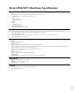
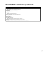
4510-MTS Modular Test System Mainframe
User’s Manual
A GREATER MEASURE OF CONFIDENCE
WARRANTY
Keithley Instruments, Inc. warrants this product to be free from defects in material and workmanship for a period of 1 year
from date of shipment.
Keithley Instruments, Inc. warrants the following items for 90 days from the date of shipment: probes, cables, rechargeable
batteries, diskettes, and documentation.
During the warranty period, we will, at our option, either repair or replace any product that proves to be defective.
To exercise this warranty, write or call your local Keithley representative, or contact Keithley headquarters in Cleveland, Ohio.
You will be given prompt assistance and return instructions. Send the product, transportation prepaid, to the indicated service
facility. Repairs will be made and the product returned, transportation prepaid. Repaired or replaced products are warranted for
the balance of the original warranty period, or at least 90 days.
LIMITATION OF WARRANTY
This warranty does not apply to defects resulting from product modification without Keithley’s express written consent, or
misuse of any product or part. This warranty also does not apply to fuses, software, non-rechargeable batteries, damage from
battery leakage, or problems arising from normal wear or failure to follow instructions.
THIS WARRANTY IS IN LIEU OF ALL OTHER WARRANTIES, EXPRESSED OR IMPLIED, INCLUDING ANY
IMPLIED WARRANTY OF MERCHANTABILITY OR FITNESS FOR A PARTICULAR USE. THE REMEDIES PROVIDED HEREIN ARE BUYER’S SOLE AND EXCLUSIVE REMEDIES.
NEITHER KEITHLEY INSTRUMENTS, INC. NOR ANY OF ITS EMPLOYEES SHALL BE LIABLE FOR ANY
DIRECT, INDIRECT, SPECIAL, INCIDENTAL OR CONSEQUENTIAL DAMAGES ARISING OUT OF THE USE OF
ITS INSTRUMENTS AND SOFTWARE EVEN IF KEITHLEY INSTRUMENTS, INC., HAS BEEN ADVISED IN
ADVANCE OF THE POSSIBILITY OF SUCH DAMAGES. SUCH EXCLUDED DAMAGES SHALL INCLUDE, BUT
ARE NOT LIMITED TO: COSTS OF REMOVAL AND INSTALLATION, LOSSES SUSTAINED AS THE RESULT OF
INJURY TO ANY PERSON, OR DAMAGE TO PROPERTY.
A
G R E A T E R
M E A S U R E
O F
C O N F I D E N C E
Keithley Instruments, Inc.
Corporate Headquarters • 28775 Aurora Road • Cleveland, Ohio 44139 • 440-248-0400 • Fax: 440-248-6168 • 1-888-KEITHLEY (534-8453) • www.keithley.com
Belgium: Sint-Pieters-Leeuw • 02-363 00 40 • Fax: 02-363 00 64 • www.keithley.nl
Italy: Milano • 02-48 39 16 01 • Fax: 02- 48 39 16 28 • www.keithley.it
China: Beijing • 8610-82251886 • Fax: 8610-82251892 • www.keithley.com.cn
Japan: Tokyo • 81-3-5733-7555 • Fax: 81-3-5733-7556 • www.keithley.jp
Finland: Helsinki • 09-5306-6560 • Fax: 09-5306-6565 • www.keithley.com
Korea: Seoul • 82-2-574-7778 • Fax: 82-2-574-7838 • www.keithley.com
France: Saint-Aubin • 01-64 53 20 20 • Fax: 01-60 11 77 26 • www.keithley.fr
Netherlands: Gorinchem • 0183-635333 • Fax: 0183-630821 • www.keithley.nl
Germany: Germering • 089/84 93 07-40 • Fax: 089/84 93 07-34 • www.keithley.de
Singapore: Singapore • 65-6747-9077 • Fax: 65-6747-2991 • www.keithley.com
Great Britain: Theale • 0118 929 7500 • Fax: 0118 929 7519 • www.keithley.co.uk
Sweden: Solna • 08-509 04 600 • Fax: 08-655 26 10 • www.keithley.com
India: Bangalore • 080 212 8027 • Fax: 080 212 8005 • www.keithley.com
Taiwan: Hsinchu • 886-3-572-9077 • Fax: 886-3-572-9031 • www.keithley.com.tw
2/04
4500-MTS Modular Test System
Mainframe User’s Manual
Microsoft® Windows, Microsoft® Excel, and Visual Basic®
are either registered trademarks or trademarks of
Microsoft® Corporation in the United States and/or other countries.
©2003, Keithley Instruments, Inc.
All rights reserved.
Cleveland, Ohio, U.S.A.
Second Printing, December 2003
Document Number: 4500MTS-900-01 Rev. B
Manual Print History
The print history shown below lists the printing dates of all Revisions and Addenda created for this manual. The
Revision Level letter increases alphabetically as the manual undergoes subsequent updates. Addenda, which are
released between Revisions, contain important change information that the user should incorporate immediately into
the manual. Addenda are numbered sequentially. When a new Revision is created, all Addenda associated with the
previous Revision of the manual are incorporated into the new Revision of the manual. Each new Revision includes a
revised copy of this print history page.
Revision A (Document Number 4500MTS-900-01) ............................................................................ March 2003
Revision B (Document Number 4500MTS-900-01) ...................................................................... December 2003
All Keithley product names are trademarks or registered trademarks of Keithley Instruments, Inc.
Other brand and product names are trademarks or registered trademarks of their respective holders.
Safety Precautions
The following safety precautions should be observed before using
this product and any associated instrumentation. Although some instruments and accessories would normally be used with non-hazardous voltages, there are situations where hazardous conditions
may be present.
This product is intended for use by qualified personnel who recognize shock hazards and are familiar with the safety precautions required to avoid possible injury. Read and follow all installation,
operation, and maintenance information carefully before using the
product. Refer to the manual for complete product specifications.
If the product is used in a manner not specified, the protection provided by the product may be impaired.
The types of product users are:
Responsible body is the individual or group responsible for the use
and maintenance of equipment, for ensuring that the equipment is
operated within its specifications and operating limits, and for ensuring that operators are adequately trained.
Operators use the product for its intended function. They must be
trained in electrical safety procedures and proper use of the instrument. They must be protected from electric shock and contact with
hazardous live circuits.
Maintenance personnel perform routine procedures on the product to keep it operating properly, for example, setting the line voltage or replacing consumable materials. Maintenance procedures
are described in the manual. The procedures explicitly state if the
operator may perform them. Otherwise, they should be performed
only by service personnel.
Service personnel are trained to work on live circuits, and perform
safe installations and repairs of products. Only properly trained service personnel may perform installation and service procedures.
Keithley products are designed for use with electrical signals that
are rated Measurement Category I and Measurement Category II, as
described in the International Electrotechnical Commission (IEC)
Standard IEC 60664. Most measurement, control, and data I/O signals are Measurement Category I and must not be directly connected to mains voltage or to voltage sources with high transient overvoltages. Measurement Category II connections require protection
for high transient over-voltages often associated with local AC
mains connections. Assume all measurement, control, and data I/O
connections are for connection to Category I sources unless otherwise marked or described in the Manual.
Exercise extreme caution when a shock hazard is present. Lethal
voltage may be present on cable connector jacks or test fixtures.
The American National Standards Institute (ANSI) states that a
shock hazard exists when voltage levels greater than 30V RMS,
42.4V peak, or 60VDC are present. A good safety practice is to expect that hazardous voltage is present in any unknown circuit
before measuring.
Operators of this product must be protected from electric shock at
all times. The responsible body must ensure that operators are prevented access and/or insulated from every connection point. In
some cases, connections must be exposed to potential human contact. Product operators in these circumstances must be trained to
protect themselves from the risk of electric shock. If the circuit is
capable of operating at or above 1000 volts, no conductive part of
the circuit may be exposed.
Do not connect switching cards directly to unlimited power circuits.
They are intended to be used with impedance limited sources.
NEVER connect switching cards directly to AC mains. When connecting sources to switching cards, install protective devices to limit fault current and voltage to the card.
Before operating an instrument, make sure the line cord is connected to a properly grounded power receptacle. Inspect the connecting
cables, test leads, and jumpers for possible wear, cracks, or breaks
before each use.
When installing equipment where access to the main power cord is
restricted, such as rack mounting, a separate main input power disconnect device must be provided, in close proximity to the equipment and within easy reach of the operator.
For maximum safety, do not touch the product, test cables, or any
other instruments while power is applied to the circuit under test.
ALWAYS remove power from the entire test system and discharge
any capacitors before: connecting or disconnecting cables or jumpers, installing or removing switching cards, or making internal
changes, such as installing or removing jumpers.
Do not touch any object that could provide a current path to the common side of the circuit under test or power line (earth) ground. Always
make measurements with dry hands while standing on a dry, insulated
surface capable of withstanding the voltage being measured.
The instrument and accessories must be used in accordance with its
specifications and operating instructions or the safety of the equipment may be impaired.
Do not exceed the maximum signal levels of the instruments and
accessories, as defined in the specifications and operating information, and as shown on the instrument or test fixture panels, or
switching card.
When fuses are used in a product, replace with same type and rating
for continued protection against fire hazard.
Chassis connections must only be used as shield connections for
measuring circuits, NOT as safety earth ground connections.
If you are using a test fixture, keep the lid closed while power is applied to the device under test. Safe operation requires the use of a
lid interlock.
5/03
If a
screw is present, connect it to safety earth ground using the
wire recommended in the user documentation.
The ! symbol on an instrument indicates that the user should refer to the operating instructions located in the manual.
The
symbol on an instrument shows that it can source or measure 1000 volts or more, including the combined effect of normal
and common mode voltages. Use standard safety precautions to
avoid personal contact with these voltages.
The
frame.
symbol indicates a connection terminal to the equipment
The WARNING heading in a manual explains dangers that might
result in personal injury or death. Always read the associated information very carefully before performing the indicated procedure.
The CAUTION heading in a manual explains hazards that could
damage the instrument. Such damage may invalidate the warranty.
Instrumentation and accessories shall not be connected to humans.
Before performing any maintenance, disconnect the line cord and
all test cables.
To maintain protection from electric shock and fire, replacement
components in mains circuits, including the power transformer, test
leads, and input jacks, must be purchased from Keithley Instruments. Standard fuses, with applicable national safety approvals,
may be used if the rating and type are the same. Other components
that are not safety related may be purchased from other suppliers as
long as they are equivalent to the original component. (Note that selected parts should be purchased only through Keithley Instruments
to maintain accuracy and functionality of the product.) If you are
unsure about the applicability of a replacement component, call a
Keithley Instruments office for information.
To clean an instrument, use a damp cloth or mild, water based
cleaner. Clean the exterior of the instrument only. Do not apply
cleaner directly to the instrument or allow liquids to enter or spill
on the instrument. Products that consist of a circuit board with no
case or chassis (e.g., data acquisition board for installation into a
computer) should never require cleaning if handled according to instructions. If the board becomes contaminated and operation is affected, the board should be returned to the factory for proper
cleaning/servicing.
Table of Contents
1
Getting Started
Introduction ........................................................................................................................................................
General information ...........................................................................................................................................
Feature overview ........................................................................................................................................
Specifications .............................................................................................................................................
Warranty information .................................................................................................................................
Contact information ...................................................................................................................................
Safety symbols and terms ..........................................................................................................................
Unpacking and Inspection ..........................................................................................................................
Optional accessories ...................................................................................................................................
Front panel familiarization .................................................................................................................................
Rear panel familiarization ..................................................................................................................................
2
1-2
1-2
1-2
1-2
1-3
1-3
1-3
1-3
1-4
1-5
1-6
Installation
Introduction ........................................................................................................................................................
Keyboard and mouse connections ......................................................................................................................
Card installation .................................................................................................................................................
Cover removal ............................................................................................................................................
Installation procedure .................................................................................................................................
Card removal ..............................................................................................................................................
Card configuration .....................................................................................................................................
Internal configuration .........................................................................................................................................
ISA bus .......................................................................................................................................................
PCI bus .......................................................................................................................................................
Trigger bus .................................................................................................................................................
Analog power bus ......................................................................................................................................
Mainframe installation considerations ...............................................................................................................
Line power connection ...............................................................................................................................
Ventilation ..................................................................................................................................................
Handling and lifting precautions ................................................................................................................
2-2
2-2
2-2
2-3
2-4
2-6
2-6
2-6
2-6
2-6
2-6
2-6
2-8
2-8
2-8
2-8
i
3
Operation
Introduction ........................................................................................................................................................ 3-2
Installed software ................................................................................................................................................ 3-2
Card software .............................................................................................................................................. 3-2
Operating system ........................................................................................................................................ 3-2
Software re-installation .............................................................................................................................. 3-2
Line power .......................................................................................................................................................... 3-3
Power requirements .................................................................................................................................... 3-3
Connecting to line power ............................................................................................................................ 3-3
Power-up procedure .................................................................................................................................... 3-3
Basic software operation .................................................................................................................................... 3-4
Main desktop .............................................................................................................................................. 3-4
4500-MTS folder ........................................................................................................................................ 3-4
Control panel ...................................................................................................................................................... 3-5
System settings ........................................................................................................................................... 3-5
Performing firmware upgrades ................................................................................................................... 3-6
Ethernet connections .......................................................................................................................................... 3-7
Connections ................................................................................................................................................ 3-7
Software configuration ............................................................................................................................... 3-7
Connecting peripherals ....................................................................................................................................... 3-8
Peripheral driver configuration ................................................................................................................... 3-8
Parallel port connections ............................................................................................................................ 3-8
Serial port connections ............................................................................................................................... 3-8
USB port connections ................................................................................................................................. 3-9
External monitor connections ..................................................................................................................... 3-9
Card connections .............................................................................................................................................. 3-10
A
ii
Specifications
List of Illustrations
1
Getting Started
Figure 1-1
Figure 1-2
4500-MTS/F mainframe front panel .......................................................................................................... 1-5
4500-MTS mainframe rear panel ............................................................................................................... 1-6
2
Installation
Figure 2-1
Figure 2-2
Figure 2-3
Figure 2-4
Figure 2-5
Keyboard/mouse connector ........................................................................................................................
Case cover removal ....................................................................................................................................
Top plate removal ......................................................................................................................................
Card installation .........................................................................................................................................
Internal mainframe configuration ..............................................................................................................
3
Operation
Figure 3-1
Figure 3-2
Figure 3-3
Figure 3-4
Figure 3-5
Figure 3-6
Figure 3-7
Figure 3-8
Typical 4500-MTS folder contents ............................................................................................................ 3-4
Control panel 4500-MTS configuration window ....................................................................................... 3-5
4500-MTS control panel Firmware Upgrade window ............................................................................... 3-6
Ethernet connections .................................................................................................................................. 3-7
Typical parallel port connections ............................................................................................................... 3-8
Typical serial port connections .................................................................................................................. 3-9
Typical USB port connections ................................................................................................................... 3-9
Typical external monitor connections ...................................................................................................... 3-10
2-2
2-4
2-5
2-5
2-7
1
List of Tables
2
Installation
Table 2-1
Analog power bus pin definitions .............................................................................................................. 2-6
1
1
Getting Started
1-2
Getting Started
4500-MTS Mainframe User’s Manual
Introduction
This user’s manual describes the mainframe used with the 4500 Modular Test System
(4500-MTS). After reading this document, the user should be able to perform the following
tasks.
•
•
•
•
Open up the mainframe (only if necessary to add cards; the unit will be shipped with any
ordered card(s) already installed).
Connect the hardware necessary to operate the mainframe.
Plug in the mainframe to a power outlet.
Turn on the power, and operate the mainframe.
General information
Feature overview
The 4500-MTS Modular Test System is intended to provide manufacturers of tunable laser
diodes, vertical cavity surface emitting lasers, edge emitting lasers, and Erbium Doped Fiber
Amplifiers, with a modular, compact, and cost-effective test platform for current and emerging
DC and optical production test requirements. The 4500 mainframe provides for space savings
(slot density), reduced cost of test (level of test integration), scalability (flexibility and future
test adaptability), and ease of use (configuration, less IEEE address overhead).
Key mainframe features include:
•
•
•
•
•
•
•
•
•
•
•
•
Ten PCI expansion slots (nine PCI instrumentations slots), one ISA slot, and one PICMG
CPU slot.
Sideband/trigger bus for cross-card measurement synchronization. Dedicated internal connector on each instrument slot.
Flat panel (FPD) color display (4500-MTS/F only).
Built in hard drive, CD-R/W, and floppy disk drives.
High-power, low-noise instrument grade power supply. Dedicated internal connector on each
instrument slot.
Serial, parallel, and USB ports.
10/100BaseT Ethernet port.
SVGA interface for driving an external monitor.
Keyboard with integrated pointing device (track-ball).
PC-based architecture.
Windows® 2000 operating system.
Stand-alone or remote operation via the ethernet port.
Specifications
Detailed specifications are located in Appendix A. For the latest specifications, check
www.keithley.com.
4500-MTS Mainframe User’s Manual
Getting Started
1-3
Warranty information
Warranty information is located at the front of this manual. Should your Model 4500-MTS
require warranty service, contact the Keithley representative or authorized repair facility in your
area for further information. When returning the instrument for repair, be sure to fill out and
include the service form at the back of this manual to provide the repair facility with the
necessary information.
Contact information
Worldwide phone numbers are listed at the front of this manual. If you have any questions,
please contact your local Keithley representative or call one of our Application Engineers at
1-800-348-3735 (U.S. and Canada only).
Safety symbols and terms
The following symbols and terms may be found on the instrument or used in this manual:
If a
screw is present, connect it to safety earth ground using the wire recommended in the
user documentation.
The ! symbol on an instrument indicates that the user should refer to the operating instructions located in the manual.
The
symbol on an instrument shows that it can source or measure 1000 volts or more,
including the combined effect of normal and common mode voltages. Use standard safety precautions to avoid personal contact with these voltages.
The
symbol indicates a connection terminal to the equipment frame.
The WARNING heading in a manual explains dangers that might result in personal injury or
death. Always read the associated information very carefully before performing the indicated
procedure.
The CAUTION heading in a manual explains hazards that could damage the instrument. Such
damage may invalidate the warranty.
Unpacking and Inspection
Inspection for damage
The Model 4500-MTS was carefully inspected electrically and mechanically before shipment.
After unpacking all items from the shipping carton, check for any obvious signs of physical
damage that may have occurred during transit. Report any damage to the shipping agent immediately. Save the original packing carton for possible future shipment.
Package content
The following items are included with every Model 4500-MTS order:
•
•
•
•
•
•
Model 4500-MTS with line cord
Ordered measurement cards already installed and configured
Software disk
Product Information CD-ROM that contains PDFs of the 4500-MTS Mainframe and Card
Manuals
Model 4500-MTS Quick Setup Guide
Additional accessories as ordered
1-4
Getting Started
4500-MTS Mainframe User’s Manual
Optional accessories
4500 measurement cards
4500 measurement cards are installed when ordered with the mainframe and can be installed in
the field (see Section 2 for installation instructions). Check www.keithley.com for updated lists
of all available cards and accessories.
Currently, the following cards are available.
4510-QIVC
•
•
Programmable three-range (30mA, 100mA, 500mA) current source with programmable
voltage clamp, source read-back, and precision voltage measurement (±6V maximum).
Programmable ±10V voltage source with source read-back and precision three-range (10µA,
500µA, 10mA) current measurement.
4511-QIVC
•
•
Programmable three-range (100mA, 300mA, 1A) current source with programmable voltage
clamp, source read-back, and precision voltage measurement (±6V maximum).
Programmable ±10V voltage source with source read-back and precision three-range (10µA,
500µA, 10mA) current measurement.
Other supported test cards
The following is a list of Keithley products that have been validated with the 4500-MTS:
•
•
•
•
•
•
KPCI-PIO32IOA and KPCI-PDISO8A (16I/16O and 8I/8O isolated digital IO)
KPCI-3130 and KPCI-3132 (8 and 2 channel analog output)
KPCI-3110 (1.25MHz multi-function AIO PCI card)
KPCI-3116 (250kHz low gain AIO PCI card)
KPCI-3108 and KPCI-3107 (100kHz multi-function AIO (3108) AI (3107))
KPCI-488.2 GPBI PCI card
Other Keithley PCI and ISA cards could be used with the 4500-MTS but have not been validated at the time of this printing.
Rack mount kit
The 4200-RM-050 rack mount kit can be used to mount the 4500-MTS in a standard 19-inch
rack.
4500-MTS Mainframe User’s Manual
Getting Started
1-5
Front panel familiarization
Figure 1-1 shows the front panel of the 4500-MTS/F mainframe. The 4500-MTS/C is similar
except it has no display.
Figure 1-1
4500-MTS/F mainframe front panel
ACTIVE
4500
MODULAR TEST SYSTEM
POWER
HARD DISK
POWER 0
1
1
2 3
I
4 5 6 7 8
Display
Displays graphical user interface, data, graphs, and system operation information
(Model 4500-MTS/F only).
2
CD-ROM R/W disk drive
Provides a way to install or update system software, manuals, and utilities. Note that
the 4500-MTS provides two IDE ports for support for hard disk and CD-ROM
R/W drives.
3
Floppy disk drive
Stores user data.
4
Display brightness
Adjust the display to the desired brightness.
5
POWER switch
Turns main system power on or off (0 = off; 1 = on).
6
HARD DISK indicator
Turns on when the internal hard disk is being accessed.
7
POWER indicator
Turns on when unit power is on.
8
ACTIVE indicator
For future use.
1-6
Getting Started
4500-MTS Mainframe User’s Manual
Rear panel familiarization
Figure 1-2 shows the rear panel of the 4500-MTS mainframe. See Section 2 for details on card
installation and Section 3 for comprehensive operation information, including peripheral connections and configuration.
Figure 1-2
4500-MTS mainframe rear panel
2
3
KEITHLEY
4500
MODULAR TEST SYSTEM
MADE IN
U.S.A.
COM 1
LPT 1
SLOT 12
1
1
4
5
6
SLOT 11
7
SLOT 10
SLOT 9
SLOT 6
SLOT 5
SLOT 4
SLOT 3
SLOT 2
SLOT 1
KEITHLEY
KEITHLEY
KEITHLEY
KEITHLEY
KEITHLEY
KEITHLEY
KEITHLEY
KEITHLEY
KEITHLEY
4510
QIVC
SLOT 8
4510
QIVC
SLOT 7
4510
QIVC
4510
QIVC
4510
QIVC
4510
QIVC
4510
QIVC
4510
QIVC
4510
QIVC
DUT
DUT
DUT
DUT
DUT
DUT
DUT
DUT
DUT
INTLK
INTLK
INTLK
INTLK
INTLK
INTLK
INTLK
INTLK
INTLK
8
Line power connection
Connects the 4500-MTS mainframe to line power (100-240V AC, 50 or 60Hz).
Connect only to a grounded outlet using the supplied line cord or the equivalent.
2
Parallel port (LPT1)
Connects the 4500-MTS to the parallel port of a printer and is assigned as LPT1.
3
Serial port (COM1)
Connects the 4500-MTS to the serial port of a printer or other peripheral and is
assigned as COM1.
4
Ethernet connector
Connects the mainframe to 10/100BaseT Ethernet and is especially useful with the
Model 4500-MTS/C.
5
USB port
Use this high-speed USB port to connect the unit to a USB device such as a printer.
6
External video connector
Connects the 4500-MTS to an external computer monitor and is especially useful
with the Model 4500-MTS/C, which has no standard display.
4500-MTS Mainframe User’s Manual
7
Getting Started
1-7
Keyboard/mouse connector
This PS/2 style connector connects the keyboard and mouse to the mainframe. Use
the supplied Y-cable to connect both keyboard and mouse to the same connector.
8
Measurement card slots
The 4500-MTS mainframe is equipped with ten PCI expansion slots (SLOT 1 to
SLOT 10). SLOT 1 through SLOT 9 are intended primarily for use with measurement
cards (451x-QIVC cards are shown in illustration). Standard PCI cards can also be
installed. Section 2 covers card installation; detailed information pertaining to specific cards can be found in documentation included with those cards.
2
Installation
2-2
Installation
4500-MTS Mainframe User’s Manual
Introduction
This section includes information on installation, including mouse and keyboard connections,
internal mainframe configuration, and card installation.
Keyboard and mouse connections
Before using the 4500-MTS, connect the keyboard and mouse to the corresponding PS/2-style
connector on the rear panel of the mainframe. Use the supplied Y-cable to connect both at the
same time. Figure 2-1 shows the connector location.
Figure 2-1
Keyboard/mouse connector
KEITHLEY
4500
MODULAR TEST SYSTEM
MADE IN
U.S.A.
COM 1
LPT 1
SLOT 12
SLOT 11
SLOT 10
SLOT 9
SLOT 6
SLOT 5
SLOT 4
SLOT 3
SLOT 2
SLOT 1
KEITHLEY
KEITHLEY
KEITHLEY
KEITHLEY
KEITHLEY
KEITHLEY
KEITHLEY
KEITHLEY
KEITHLEY
4510
QIVC
SLOT 8
4510
QIVC
SLOT 7
4510
QIVC
4510
QIVC
4510
QIVC
4510
QIVC
4510
QIVC
4510
QIVC
4510
QIVC
DUT
DUT
DUT
DUT
DUT
DUT
DUT
DUT
DUT
INTLK
INTLK
INTLK
INTLK
INTLK
INTLK
INTLK
INTLK
INTLK
Keyboard/mouse connector
Card installation
WARNING
The following information is intended only for qualified service
personnel. Do not attempt these procedures unless you are qualified
to do so. Some of these procedures may subject you to electric
shock, possibly causing personal injury or death.
NOTE
The 4500-MTS mainframe is shipped from the factory with ordered measurement cards already installed. The following procedure is intended
for those who wish to install additional cards in the field.
4500-MTS Mainframe User’s Manual
Installation
2-3
Cover removal
WARNING
Disconnect the line cord and all other cables from the mainframe
before removing the cover.
Tools Required
#1 Tip Phillips Screwdriver
Wrist ground strap
Procedure
1. Remove the six (6) screws that secure the cover to the case located on the bottom side of
chassis (Figure 2-2 on page 2-4).
2. Carefully remove the cover from the case by sliding it off the top of the chassis.
3. Loosen the twelve (12) screws that secure the flat cover plate to the chassis, slide the plate
forward (toward rear of chassis) about 0.25" and lift off (Figure 2-3).
WARNING
The safety shield that covers the fan and front area should not be
removed for card installation/removal or cover removal, and it
should be removed only for servicing. Hazardous voltages will be
exposed when the shield is removed. Rotating fan blades can cause
minor cuts or injury. Keep hands clear when servicing.
4. To re-install, install the flat cover plate and tighten the twelve (12) screws, place the cover on
the case, then attach it with the six (6) screws.
2-4
Installation
4500-MTS Mainframe User’s Manual
Installation procedure
Install a 4500 card using the procedure below and Figure 2-4 on page 2-5 as a guide. This
procedure assumes that the case cover is already removed as previously discussed.
CAUTION
Handle the card only by the edges to avoid contamination that
could affect measurement quality. Do not touch PC board traces or
edge connector contacts. Use a ground strap and proper grounding
techniques to avoid damage caused by static discharge.
1. Remove the desired slot cover plate from the rear panel by removing the securing screw (1)
and bracket.
2. Remove the PCI card retainer by loosening the three (3) retaining screws and sliding the
bracket off.
3. Carefully remove the card from its antistatic (shipping) bag.
4. Position the card above the appropriate PCI slot, aligning the card with the card edge rails
and rear slot opening. Line up the edge connectors with the slot connectors on the backplane,
and then carefully insert the card into those connectors. Make sure the card is properly seated
in all connectors by applying firm, even pressure to the top edge of the card.
5. Install the screw (1) at the rear panel location to secure the card.
6. Re-install the PCI card retainer; retighten the three (3) screws.
7. Replace the mainframe top cover plate and cover.
Figure 2-2
Case cover removal
Case Cover
Slide Cover Off Carefully
Remove Six (6) Screws
4500-MTS Mainframe User’s Manual
Installation
2-5
Figure 2-3
Top plate removal
Loosen Twelve (12) Screws
Flat Cover Plate
Slide Cover Toward Rear of Chassis 0.25”.
Lift Flat Cover Plate Off.
Figure 2-4
Card installation
4500 Card
PCI Retainer Bracket
Remove Securing Screw and Bracket.
Reuse Screw to Secure Card.
Install Card in Desired
PCI Slot.
Loosen Three (3) Screws
2-6
Installation
4500-MTS Mainframe User’s Manual
Card removal
To remove a card, first disconnect all cables connected to the card, remove the rear plate screw,
and then remove the card from the slot.
Card configuration
The operating system software will automatically recognize and configure the card the next time
the mainframe power is turned on. Card operation is covered in Section 3.
Internal configuration
Figure 2-5 shows the internal configuration of the mainframe. The major components are outlined below.
NOTE
The exact internal configuration may be slightly different depending on
hardware revision level.
ISA bus
Two ISA bus slots are included, one of which is a shared ISA/PCI slot, while the other slot is
ISA-only.
PCI bus
Nine slots are 5V, 33MHz, PCI 2.1 – 2.3 local bus interface slots, and they are intended
primarily for use with 4500 measurement cards but standard 5V PCI cards for other purposes
can also be installed.
NOTE
3.3V PCI cards can also be used. 3.3V PCI cards must be placed in
opposite direction, and the entire bridge (4 slots) will be 3.3V powered.
3.3V operation cannot be configured on an individual slot basis.
Trigger bus
This bus is available only for use with 4500 PCI cards. It synchronizes the 4500 PCI cards by
using a triggering protocol.
Analog power bus
Each of the nine PCI expansion slots also has an analog power bus that is used to supply power
to the 4500 measurement cards. The connection pin layout of the analog power bus is shown in
Table 2-1.
Table 2-1
Analog power bus pin definitions
Pin
1
2
3
4
5
6
7
8
9
Description
NC
NC
NC
NC
NC
NC
NC
NC
NC
Pin
10
11
12
13
14
15
16
17
18
Description Pin Description
GND
19
NC
GND
20
NC
GND
21
+48V
+48V
22
+48V
+48V
23
NC
NC
24
NC
NC
25
+48V
+48V
26
+48V
+48V
—
—
4500-MTS Mainframe User’s Manual
Installation
2-7
Figure 2-5
Internal mainframe configuration
Measurement
card slots
(trigger bus)
Measurement
card slots
(PCI bus)
Power
supply
Backplane
Memory
Measurement
card slots
(analog bus)
Hard
drive
PCI card
retainer
!
WARNING:
HAZARDOUS VOLTAGE EXPOSED
WHEN COVER OPENED
Safety shield
(do not remove)
! CAUTION
Rotating Fan blades.
Can cause serious injury
or cut.
Keep hands clear when
servicing.
Disk
drives
2-8
Installation
4500-MTS Mainframe User’s Manual
Mainframe installation considerations
The 4500-MTS mainframe can be operated in various locations such as on a desktop or workbench, or it can be installed in a rack using the optional rack mount kit. However, the following
considerations should be taken into account.
Line power connection
To avoid problems caused by fluctuating power, the 4500-MTS should be connected to a dedicated 100-240V, 50 to 60Hz line power source. In particular, avoid connecting the unit to the
same circuit as transient-generating loads, such as large electric motors.
Ventilation
The 4500-MTS mainframe should be operated in a location that provides sufficient ventilation
to assure adequate cooling. Be especially sure not to block the screened covered air input vents
and vertical vents on the rear panel. Avoid installing the unit in the same rack with other equipment that generates excessive heat, and allow sufficient clearance above and below heat-generating equipment. In some cases, it may be necessary to install additional forced air rack
ventilation.
CAUTION
Operating the 4500-MTS without adequate ventilation may cause
damage due to overheating, possibly voiding the warranty.
Handling and lifting precautions
WARNING
To avoid possible personal injury when moving or lifting the
4500-MTS mainframe, it is recommended that the following precautions be observed:
•
Any handling or lifting of the mainframe should be performed
by a minimum of two persons.
•
The 4500-MTS should be properly supported while it is being
secured in a rack. Install the 4500-MTS on a work surface or in a
rack with optional rack mount kit.
•
Lift the 4500-MTS from the bottom.
•
Do not lift from the front bezel.
3
Operation
3-2
Operation
4500-MTS Mainframe User’s Manual
Introduction
This section contains information on connecting the mainframe to line power, ethernet connections, and connecting peripherals. Basic software information is also included.
Installed software
Card software
The necessary software for any measurement cards that were purchased with the mainframe will
already be installed. Software includes:
•
•
•
Card driver — provides the necessary interface between user test programs and the card.
Example program — provides a basic graphical interface to measurement cards to demonstrate their capabilities.
Application program examples — example programs for typical applications intended as a
starting point for users to write their own application programs.
Consult the documentation supplied with the measurement card(s) for details.
Operating system
The 4500-MTS mainframe is shipped from the factory with Windows® 2000 already installed.
For detailed information on using the operating system, consult the supplied documentation or
Windows® 2000 online help.
Software re-installation
Should it become necessary, both card software and operating system can be re-installed from
the supplied CD-ROM. Consult the pertinent printed or electronic documentation for installation
procedures.
4500-MTS Mainframe User’s Manual
Operation
3-3
Line power
Power requirements
The 4500-MTS is designed to operate from line power sources in the range of 100 to 240V AC
at a line frequency of 50 to 60Hz.
CAUTION
Operating the mainframe on line voltages outside this range may
result in damage, voiding the warranty.
Connecting to line power
Connect the mainframe to line power as follows:
1. Connect one end of the supplied line cord or the equivalent to the rear panel line power
receptacle on the rear panel of the mainframe.
2. Connect the other end of the line cord to a grounded outlet.
WARNING
To avoid a possible shock hazard, connect the mainframe only to a
grounded outlet using the supplied line cord or the equivalent that
has an integral ground wire.
Power-up procedure
Follow these steps to turn on the power:
1. Turn on the power by pressing in on the front panel POWER switch.
2. When the unit is first turned on, the operating system will go through its boot-up sequence in
the usual manner.
3. If this is the first time the unit has been powered up since installing a new measurement card,
Windows® plug-and-play will automatically configure the new hardware, and you may be
prompted to click OK to continue, or to insert the appropriate disk if the operating system
cannot locate the necessary driver. In either case, follow the instructions on the screen to
complete installation.
4. Log into Windows® 2000: “User: kiuser”, “Password:” <Enter>.
5. Once boot-up and installation are complete, the typical start-up desktop will be displayed.
3-4
Operation
4500-MTS Mainframe User’s Manual
Basic software operation
A basic overview of supplied software is given below. For complete details on using the software, refer to the User’s Manual supplied with the card.
Main desktop
The 4500-MTS icon on the main startup desktop allows access to system facilities such as disk
drives, while the 4500-MTS folder accesses the supplied software files.
4500-MTS folder
Figure 3-1 shows the typical contents of the 4500-MTS folder (actual contents may vary,
depending on installed cards and software version). Contents include:
•
•
•
•
•
Release notes — includes information on this particular version of 4500-MTS software.
Help files — Contains detailed information for using card driver function calls for the
software platforms supported by the 4500-MTS. For example, the C Help File covers using
the 4500 software with C-based platforms, while the VB Help File has details for use with
Visual Basic®.
4500-MTS Real-Time Manager — The real-time manager, which runs in the background,
is launched when the system boots and the user logs in. Note that the real-time manager task
will automatically execute when the system boots.
Reset 4500 — Resets the mainframe to default conditions.
VB Embedded Sweep Example — A Visual Basic® application that demonstrates basic
card capabilities, included embedded sweeps.
Figure 3-1
Typical 4500-MTS folder contents
4500-MTS Mainframe User’s Manual
Operation
3-5
Control panel
To access the control panel, click on 4500-MTS icon in the Windows® Control Panel.
Figure 3-2 shows the control panel. The System Settings tab allows you to set line frequency,
generate system information, and enable/disable the emulation mode. The Firmware Upgrade
tab allows you to perform system firmware upgrades.
Figure 3-2
Control panel 4500-MTS configuration window
System settings
To change or review system settings, click on the System Settings tab in the 4500-MTS
Configuration window (see Figure 3-2).
Enabling/disabling the emulation mode
There are two basic operating modes for the 4500-MTS system: emulation mode and real mode.
The emulation mode provides pretend cards for running existing 4500 programs or developing
new ones. The Real mode (Emulation mode disabled) lets programs control 4500 cards in the
system.
To select the operating mode, double-click on the 4500-MTS icon in the Windows Control
Panel, click on the System Settings tab, and then Enable or Disable the emulation mode as
desired. Click OK to select.
NOTE
Emulation mode provides basic card functionality but may not provide a
complete emulation of a card.
Generating system information
To generate information files on system details or for technical support, click on the corresponding button (Generate System Info File or Generate Tech Support Files). The corresponding
information files will be stored on the hard drive in standard ASCII text format for later review.
Setting line frequency
The line frequency setting should be the same as the power line frequency for optimum
measurement noise performance. To set the line frequency, click on the Line Frequency tab in
the 4500-MTS Configuration window, and then set line frequency to the correct setting and
click OK.
3-6
Operation
4500-MTS Mainframe User’s Manual
Setting defaults
Set Defaults will bring up a window to allow you to set up default settings for the selected card.
The settings include: Current Source Range, Current Source Voltage Compensation, Current
Measurement Range, Current Source Readback State, Voltage Measure State, Voltage Readback
State, Current Measure State, and Measurement Speed (NPLC).
Performing firmware upgrades
Firmware upgrades can be performed by clicking on the Firmware Upgrade tab (see
Figure 3-3). Follow the instructions included with the upgrade software to complete the upgrade
process.
Figure 3-3
4500-MTS control panel Firmware Upgrade window
4500-MTS Mainframe User’s Manual
Operation
3-7
Ethernet connections
Connections
When making Ethernet connections, use only Category 5 UTP cable. Use a straight-through
cable for connections to a network wall plate jack, hub, or patch panel. Use a cross-over cable
for connections directly to another computer. Figure 3-4 shows typical network connections to
the 4500-MTS Ethernet jack, which is a standard RJ-45 connector.
Figure 3-4
Ethernet connections
4500-MTS Mainframe
KEITHLEY
4500
MODULAR TEST SYSTEM
MADE IN
U.S.A.
COM 1
LPT 1
SLOT 12
SLOT 11
SLOT 10
SLOT 9
SLOT 6
SLOT 5
SLOT 4
SLOT 3
SLOT 2
SLOT 1
KEITHLEY
KEITHLEY
KEITHLEY
KEITHLEY
KEITHLEY
KEITHLEY
KEITHLEY
KEITHLEY
KEITHLEY
4510
QIVC
SLOT 8
4510
QIVC
SLOT 7
4510
QIVC
4510
QIVC
4510
QIVC
4510
QIVC
4510
QIVC
4510
QIVC
4510
QIVC
DUT
DUT
DUT
DUT
DUT
DUT
DUT
DUT
DUT
INTLK
INTLK
INTLK
INTLK
INTLK
INTLK
INTLK
INTLK
INTLK
To network
connection
Category 5
UTP cable
Ethernet
connector
Software configuration
NOTE
The 4500-MTS software should be installed on the external computer on
the network prior to software configuration.
To configure the 4500-MTS for use on a network:
1.
2.
3.
4.
Open the Windows® Control Panel.
Double-click on the Network and Dial-up Connections icon.
Enter the required IP address, as well as DNS and Gateway (router) information.
Click OK to complete the process.
3-8
Operation
4500-MTS Mainframe User’s Manual
Connecting peripherals
Peripheral driver configuration
In most instances, Windows® plug-and-play will automatically install the necessary drivers for
peripherals connected to the parallel, serial, or USB ports. However, some cases may require
user configuration. In general, peripherals can be manually configured as follows:
•
•
For printers, use the Add Printer icon in the Printers folder.
For other hardware use the Add/Remove Hardware icon in the Control Panel.
See the Windows® and peripheral documentation for details.
Parallel port connections
Typical connections to the parallel port are shown in Figure 3-5. Be sure to use shielded parallel
cables to avoid electrical interference that could have detrimental affects on measurement
quality.
Figure 3-5
Typical parallel port connections
4500-MTS Mainframe
Parallel port
(LPT1)
KEITHLEY
4500
MODULAR TEST SYSTEM
MADE IN
U.S.A.
COM 1
LPT 1
Printer
SLOT 12
Parallel port
SLOT 11
SLOT 10
SLOT 9
SLOT 6
SLOT 5
SLOT 4
SLOT 3
SLOT 2
SLOT 1
KEITHLEY
KEITHLEY
KEITHLEY
KEITHLEY
KEITHLEY
KEITHLEY
KEITHLEY
KEITHLEY
KEITHLEY
4510
QIVC
SLOT 8
4510
QIVC
SLOT 7
4510
QIVC
4510
QIVC
4510
QIVC
4510
QIVC
4510
QIVC
4510
QIVC
4510
QIVC
DUT
DUT
DUT
DUT
DUT
DUT
DUT
DUT
DUT
INTLK
INTLK
INTLK
INTLK
INTLK
INTLK
INTLK
INTLK
INTLK
Shielded parallel cable
Serial port connections
Typical connections to the serial port are shown in Figure 3-6. Be sure to use a shielded parallel
cable such as the Keithley Model 7009 to avoid electrical interference that could have detrimental affects on measurement quality. Note that it may be necessary to set up port parameters such
as baud rate, parity, and stop bits under Properties for your serial port device.
4500-MTS Mainframe User’s Manual
Operation
3-9
Figure 3-6
Typical serial port connections
4500-MTS Mainframe
KEITHLEY
Serial port
(COM1)
4500
MODULAR TEST SYSTEM
MADE IN
U.S.A.
COM 1
Printer or other
serial device
LPT 1
SLOT 12
SLOT 11
Serial port
SLOT 10
SLOT 9
SLOT 6
SLOT 5
SLOT 4
SLOT 3
SLOT 2
SLOT 1
KEITHLEY
KEITHLEY
KEITHLEY
KEITHLEY
KEITHLEY
KEITHLEY
KEITHLEY
KEITHLEY
KEITHLEY
4510
QIVC
SLOT 8
4510
QIVC
SLOT 7
4510
QIVC
4510
QIVC
4510
QIVC
4510
QIVC
4510
QIVC
4510
QIVC
4510
QIVC
DUT
DUT
DUT
DUT
DUT
DUT
DUT
DUT
DUT
INTLK
INTLK
INTLK
INTLK
INTLK
INTLK
INTLK
INTLK
INTLK
Shielded serial cable
USB port connections
Typical connections to the USB port are shown in Figure 3-7. Use a type A male USB connector
to make connections to the 4500-MTS. Use the appropriate connector (A or B) to make connections to the USB peripheral device.
Figure 3-7
Typical USB port connections
4500-MTS Mainframe
KEITHLEY
4500
MODULAR TEST SYSTEM
MADE IN
U.S.A.
COM 1
Printer or other
USB device
USB
port
LPT 1
SLOT 12
USB port
SLOT 11
SLOT 10
SLOT 9
SLOT 6
SLOT 5
SLOT 4
SLOT 3
SLOT 2
SLOT 1
KEITHLEY
KEITHLEY
KEITHLEY
KEITHLEY
KEITHLEY
KEITHLEY
KEITHLEY
KEITHLEY
KEITHLEY
4510
QIVC
SLOT 8
4510
QIVC
SLOT 7
4510
QIVC
4510
QIVC
4510
QIVC
4510
QIVC
4510
QIVC
4510
QIVC
4510
QIVC
DUT
DUT
DUT
DUT
DUT
DUT
DUT
DUT
DUT
INTLK
INTLK
INTLK
INTLK
INTLK
INTLK
INTLK
INTLK
INTLK
USB cable
External monitor connections
Typical connections to an external monitor are shown in Figure 3-8. You can set up necessary
display properties using the Control Panel Display icon or by right-clicking on the main
Desktop and then selecting Properties.
NOTE
The minimum display resolution for the supplied 4500 example program
is 600 × 800.
3-10
Operation
4500-MTS Mainframe User’s Manual
Figure 3-8
Typical external monitor connections
4500-MTS Mainframe
External monitor
connector
KEITHLEY
4500
MODULAR TEST SYSTEM
MADE IN
U.S.A.
External monitor
COM 1
LPT 1
SLOT 12
Monitor connection
on rear
SLOT 11
SLOT 10
SLOT 9
SLOT 6
SLOT 5
SLOT 4
SLOT 3
SLOT 2
SLOT 1
KEITHLEY
KEITHLEY
KEITHLEY
KEITHLEY
KEITHLEY
KEITHLEY
KEITHLEY
KEITHLEY
KEITHLEY
4510
QIVC
SLOT 8
4510
QIVC
SLOT 7
4510
QIVC
4510
QIVC
4510
QIVC
4510
QIVC
4510
QIVC
4510
QIVC
4510
QIVC
DUT
DUT
DUT
DUT
DUT
DUT
DUT
DUT
DUT
INTLK
INTLK
INTLK
INTLK
INTLK
INTLK
INTLK
INTLK
INTLK
Monitor cable
Card connections
Refer to the card documentation for detailed information on card connections. For the
4510-QIVC and 4511-QIVC cards, refer to Section 2 of the 4510-QIVC User’s Manual for
connection information.
A
Specifications
Model 4500-MTS Mainframe Specifications
DESCRIPTION
The 4500-MTS is a fully integrated, instrument grade industrial computer with the following features:
• Total of 10 PCI slots, 9 PCI instrument slots available to user. 1 ISA instrument slot. 1 PICMG CPU slot.
• Sideband/trigger bus for cross-card measurement synchronization. Dedicated connector on each instrument slot.
• High-power, low-noise instrument grade power supply. Dedicated connector on each instrument slot.
• Embedded PC with Windows operating system.
• SVGA interface for driving an external monitor.
• 10/100 Base-T LAN interface.
• USB interface.
• RS-232 interface.
• Printer interface.
• Hard disk drive.
• CD-RW disk drive.
• Floppy disk drive.
• Steel chassis with enhanced cooling, painted cover, and plastic front bezel.
• Optional integrated Flat Panel Display.
• Full size keyboard with integrated pointing device.
4500-MTS/C
4500-MTS/F
ACCESSORIES:
The following instruments were specifically designed for use with the 4500-MTS mainframe:
• 4511-QIVC – 1A, Quad IV instrument card.
• 4510-QIVC – 500mA, Quad IV instrument card.
The following is a current list of Keithley products that have been validated with the 4500-MTS:
• KPCI-PIO32IOA and KPCI-PDISO8A (16I/16O and 8I/8O Isolated Digital IO)
• KPCI-3130 and KPCI–3132 (8 and 2 channel Analog Output)
• KPCI-3110 (1.25MHz Multi function AIO PCI Card)
• KPCI-3116 (250kHz Low Gain AIO PCI Card)
• KPCI-3108 and KPCI-3107 (100kHz Multi function AIO (3108) AI (3107))
• KPCI-488.2 GPIB PCI Card
Other Keithley PCI and ISA cards could be used with the 4500-MTS but have not been verified at the time of this printing.
HW 1/28/04
Rev. C
Page 1 of 3
Model 4500-MTS Mainframe Specifications
SYSTEM BACKPLANE:
PCI
Slots: Ten total. Nine slots are available for PCI instrumentation. One slot reserved.
Compliance: PCI 2.1 – 2.3 (Determined by embedded PC).
ISA
Slots: 1, 16 bit slot.
Compliance: PICMG 2.0
PCI/ISA
Slots: 1
Compliance: PICMG 2.0
SIDEBAND/TRIGGER BUS
Reserved for use by 45XX instrument cards.
SYSTEM POWER SUPPLIES:
The 4500-MTS mainframe utilizes 2 power supplies. The ATX power supply provides power to the computer components (e.g. embedded PC, disk drives, etc…) and
PCI bus. The Analog power supply provides 48V power to 45XX instrument card output stages.
ATX Power Supply: 70Watts Max.
Output Voltage (Max Current): +3.3V (14 Amps), +5V (20 Amps), -5V (0.3 Amps), +12V (6 Amps), -12V (0.8 Amps).
Analog Power Supply: +48V (16 Amps max).
EMBEDDED SINGLE BOARD COMPUTER (SBC):
FEATURES:
Processor: Intel Pentium 4, 2 GHz.
Chipset: Intel 845.
Memory: Up to 2 GB, 200/266 MHz DDR SDRAM on two 184-pin DIMM sockets.
Video: ATI Mobility M6 graphics controller, 16 Mbytes 200 MHz DDR SDRAM display cache. Flat panel LVDS support and simultaneous SVGA support.
LAN: 10/100 Base-T. RJ-45 connector on SBC retaining bracket.
USB: One port on SBC retaining bracket. Two ports on 4500-MTS front panel.
Serial: One port, 9 pin, COM1.
Parallel: One port, 25 pin.
IDE: Two EIDE ports with ULTRA DMA 33/66/100 support.
Floppy: One port.
Keyboard/Mouse: One 9-pin DIN connector on SBC retaining bracket. Y-cable provided.
DISK DRIVES:
Hard drive: Interface - EIDE; Capacity - 40 GB.
Floppy disk: Size - 3.5”; Capacity - 1.44 MB.
CD-RW: Interface - ATAPI, EIDE.
CHASSIS:
Material: Stainless steel inner chassis and rear panel. Painted steel cover.
Fan: High reliability cooling fan.
HW 1/28/04
Rev. C
Page 2 of 3
Model 4500-MTS Mainframe Specifications
GENERAL SPECIFICATIONS
POWER SUPPLY:
Power Per Slot Max: 96W for 48V; 8.75W for ATX.
Mains: Push Button ON/OFF switch/fuse/power module combo.
TEMPERATURE:
Operating: 0° to +40°C (with no accessory cards)
Storage: -15° to 60°C
HUMIDITY:
Operating: 5% to 70% RH, non-condensing
ALTITUDE: Maximum 2000m above sea level. For Indoor Use Only.
POWER REQUIREMENTS: 100-240VAC, 50/60Hz.
INPUT POWER RATING: 1kVA max.
WARM UP TIME: 1 hour
REGULATORY COMPLIANCE:
Safety: Conforms to European Union Directive 73/23/EEC, EN61010-1, CAT I.
EMC: Conforms to European Union Directive 89/336/EEC, EN61326-1.
DIMENSIONS: 22.3cm high x 43.6cm wide x 56.5cm deep (8.75in. x 2.17in. x 22.25in.).
WEIGHT (approx.): 26.3kg (58lbs) for base system (excluding multi-channel cards, cables, keyboard, etc).
HW 1/28/04
Rev. C
Page 3 of 3
Index
Numerics
4500 1-4
4500 measurement cards 1-4
4500-MTS folder 3-4
4510 1-4
4511 1-4
G
General information 1-2
Generating system information 3-5
Getting Started 1-1
H
B
Handling and lifting precautions 2-8
Basic software operation 3-4
I
C
Card configuration 2-6
Card connections 3-10
Card installation 2-2
Card removal 2-6
Card software 3-2
Connecting peripherals 3-8
Connecting to line power 3-3
Contact information 1-3
Phone number 1-3
Control panel 3-5
Cover removal 2-3
Inspection for damage 1-3
Installation 2-1
Installation procedure 2-4
Installed software 3-2
Internal configuration 2-6
Analog power bus 2-6
ISA bus 2-6
PCI bus 2-6
Trigger bus 2-6
Introduction 1-2, 2-2, 3-2
K
Keyboard and mouse connections 2-2
E
Enabling/disabling the demo mode 3-5
Ethernet connections 3-7
External monitor connections 3-9
F
L
Line power 3-3
Line power connection 2-8
M
Feature overview 1-2
firmware upgrades 3-6
Front panel familiarization 1-5
Main desktop 3-4
Mainframe installation considerations 2-8
i-1
O
S
Operating system 3-2
Operation 3-1
Optional accessories 1-4
Other supported test cards 1-4
Safety symbols and terms 1-3
Serial port connections 3-8
Setting defaults 3-6
Setting line frequency 3-5
Software configuration 3-7
Software re-installation 3-2
Specifications 1-2, A-1
System settings 3-5
P
Package content 1-3
Parallel port connections 3-8
Performing firmware upgrades 3-6
Peripheral driver configuration 3-8
Power requirements 3-3
Power-up procedure 3-3
R
U
Unpacking and Inspection 1-3
USB port connections 3-9
V
Rack mount kit 1-4
Rear panel familiarization 1-6
Ventilation 2-8
W
Warranty information 1-3
i-2
Service Form
Model No.
Serial No.
Date
Name and Telephone No.
Company
List all control settings, describe problem and check boxes that apply to problem.
❏
Intermittent
❏
Analog output follows display
❏
Particular range or function bad; specify
❏
❏
IEEE failure
Front panel operational
❏
❏
Obvious problem on power-up
All ranges or functions are bad
❏
❏
Batteries and fuses are OK
Checked all cables
Display or output (check one)
❏
❏
❏
Drifts
Unstable
Overload
❏
❏
Unable to zero
Will not read applied input
❏
❏
Calibration only
❏
Certificate of calibration required
Data required
(attach any additional sheets as necessary)
Show a block diagram of your measurement system including all instruments connected (whether power is turned on or not). Also, describe
signal source.
Where is the measurement being performed? (factory, controlled laboratory, out-of-doors, etc.)
What power line voltage is used?
Relative humidity?
Ambient temperature?
Other?
Any additional information. (If special modifications have been made by the user, please describe.)
Be sure to include your name and phone number on this service form.
°F
Specifications are subject to change without notice.
All Keithley trademarks and trade names are the property of Keithley Instruments, Inc.
All other trademarks and trade names are the property of their respective companies.
A
G R E A T E R
M E A S U R E
O F
C O N F I D E N C E
Keithley Instruments, Inc.
Corporate Headquarters • 28775 Aurora Road • Cleveland, Ohio 44139 • 440-248-0400 • Fax: 440-248-6168 • 1-888-KEITHLEY (534-8453) • www.keithley.com
Belgium: Sint-Pieters-Leeuw • 02-363 00 40 • Fax: 02-363 00 64 • www.keithley.nl
Italy: Milano • 02-48 39 16 01 • Fax: 02-48 39 16 28 • www.keithley.it
China: Beijing • 8610-82251886 • Fax: 8610-82251892 • www.keithley.com.cn
Japan: Tokyo • 81-3-5733-7555 • Fax: 81-3-5733-7556 • www.keithley.jp
Finland: Helsinki • 09-5306-6560 • Fax: 09-5306-6565 • www.keithley.com
Korea: Seoul • 82-2-574-7778 • Fax: 82-2-574-7838 • www.keithley.com
France: Saint-Aubin • 01-64 53 20 20 • Fax: 01-60 11 77 26 • www.keithley.fr
Netherlands: Gorinchem • 0183-635333 • Fax: 0183-630821 • www.keithley.nl
Germany: Germering • 089/84 93 07-40 • Fax: 089/84 93 07-34 • www.keithley.de
Singapore: Singapore • 65-6747-9077 • Fax: 65-6747-2991 • www.keithley.com
Great Britain: Theale • 0118 929 7500 • Fax: 0118 929 7519 • www.keithley.co.uk
Sweden: Solna • 08-509 04 600 • Fax: 08-655 26 10 • www.keithley.com
India: Bangalore • 080 212 8027 • Fax : 080 212 8005 • www.keithley.com
Taiwan: Hsinchu • 886-3-572-9077 • Fax: 886-3-572-9031 • www.keithley.com.tw
© Copyright 2004 Keithley Instruments, Inc.
Printed in U.S.A
2/04