1
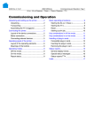
12/08 Rev. 5.01-01
USER MANUAL
64-xx
Commissioning & Operation
Mounting the Printer ...................................... 2
Unpacking the 64-xx ................................. 2
Carrying the 64-xx ..................................... 3
Mounting the 64-xx .................................... 4
Printer connections ................................... 5
Operator panel .......................................... 7
Operating modes ....................................... 9
Basic Operating Procedures ....................... 10
Connecting the printer ............................. 10
Setting the interface ................................ 11
Offline operation ...................................... 11
Online operation ...................................... 12
Creating a print job ..................................13
Transferring a print job .............................13
Using CompactFlash cards ......................15
Setting the realtime clock .........................16
Outputting the realtime clock value using
Easy Plug .................................................16
Starting to print ............................................17
Settings for the material type ...................17
Printing the status report ..........................17
2
12/08 Rev. 5.01-01
USER MANUAL
Commissioning & Operation
64-xx
Mounting the Printer
Unpacking the 64-xx
A
1. Lift off the lid of the shipping box [1].
2. Take out the plastic bag containing the
accessories [1B].
3. Lift off the styrofoam support [1A].
4. Part the plastic cover [2].
B
WARNING!
Printers with mounted cutter: The
cutter may cause cut injuries.
« Do not grasp the cutter [4A] as a
handle.
« Use the cutter motor [4B] as a
handle.
[1]
Shipping box without lid:
A Styrofoam support
B Accessories
[2]
Open the plastic bag...
A
B
[4]
D o n ´t use the cutter as a handle!
5. Grab the printer from underneath and lift it
out. The material feed slot in the back wall
of the printer [3A] can be used as a
handle.
A
B
¯ Printers with mounted cutter: The motor
[4B], but not the cutter [4A] may be used as
a handle!
C
CAUTION! - Do not lift the printer by
the front cover [4B]. The front cover is
a movable part not designed for
handling stress.
6. Place the printer on a level surface in its
usual operating position (rubber feet [4C]
at the bottom).
¯ The original packaging should always be
used for transporting the printer!
[3]
Lift the printer out of the box.
A Back wall of printer (not visible)
B Front cover (do not use for lifting)
C Rubber feet
3
12/08 Rev. 5.01-01
USER MANUAL
Commissioning & Operation
64-xx
Carrying the 64-xx
WARNING!
The 64-xx is a heavy printer. The weight depends on the printer type and
equipement and can vary from 20 kg (64-04/05) up to 29.5 kg (64-08 Dispenser).
A bad carrying technique can cause back injury.
« Try to lift the printer in a safe way, for example by
– carrying it close to your body, and by
– bending your knees, not your back.
« To carry the printer, put one hand under the base plate and the other into the
feed slot at the back of the printer.
CAUTION! - Do not lift the printer by the front cover (window side), as this
can damage it!
A
[5]
B
Carrying the 64-xx safely (A: back – grab by the feed slot, B: front – grab by the base plate).
4
12/08 Rev. 5.01-01
USER MANUAL
Commissioning & Operation
64-xx
Mounting the 64-xx
The 64-xx has been designed as a desktop printer, which means that it is
normally mounted in an upright position on a table [2]. Other sufficiently large,
level and sturdy surfaces can also be used as a base.
WARNING!
When choosing a base for the printer, observe the following guidelines to
avoid dangerous operating conditions:
« The base needs to be at least as deep and wide as the printer itself.
« The surface needs to be level, solid and dry.
« The printer’s fan and ventilation slits must not be obstructed, as the device
may overheat otherwise.
« The printer must not be mounted in the immediate vicinity of other heat
sources.
« The environmental conditions specified (temperature, air humidity, etc.)
need to be complied with.
« The power cable should be run to the printer so that
– nobody will trip on it, and that
– the power plug can easily be pulled out if necessary.
[6]
The correct orientation of the 64-04.
5
12/08 Rev. 5.01-01
USER MANUAL
Commissioning & Operation
64-xx
Printer connections
CAUTION!
Add-on devices of an inferior quality may damage the printer!
« Connect the printer only to devices that fulfil SELV (safety extra-low voltage) circuit requirements acc. to EN 60950!
« Only connect OEM devices.
I
H
A
J
B
C
L
M
K
D
E
F
G
[7]
Back of the 64-xx with the following options installed: USI board (H), connector for remote
operator panel (I) and start/stop signal input (J).
A Card slot
For SD/MMC cards; is not yet supported
B Card slot
For CompactFlash cards; used for storing fonts, logos, graphics, etc.
C USB interface type B (device)
For transfer of print data
D 2x USB interface type A (host)
To connect devices (e.g. keyboard, scanner)
E RS232 interface
For serial transfer of print data
F Status-LED/Ethernet
G Ethernet interface
To connect to an „Ethernet 10/100 Base T“ network
6
12/08 Rev. 5.01-01
USER MANUAL
Commissioning & Operation
64-xx
H Optional: Signal interface USI
y 4 inputs / 8 outputs
y Standard at „64-xx Dispenser A“
I
Optional: Mini-DIN connector
To connect a remote operator panel
J Optional: start/stop signal input
y Standard at 64-xx Dispenser
y To connect a foot switch (signal starts printer) or a stacker (signal stops
printer)
K Centronics interface
For parallel transfer of print data (cable is inclusive)
L Power switch
Turns the printer on/off
M Mains power supply connector
Connection to a mains socket using the provided power cable
7
12/08 Rev. 5.01-01
USER MANUAL
Commissioning & Operation
64-xx
Operator panel
Display
Prog button
Feed button
Online button
Cut button
[8]
Operator panel of the 64-xx.
Display
With 32 digits and two lines, the display shows the operating conditions (modes) for parameters, values, status and errors. You can select the language
you want to use for the display. Backlighting ensures good legibility.
Button functions
The buttons offer a multitude of operating functions. A logical menu structure
is used for operation. The meaning of each button varies according to the
operating mode and the menu item. Additionally, special functions have been
programmed for certain button combinations.
Depending on the modes and menu levels, the following functions apply for
each button:
Online button
y For switching between online and offline mode.
y For confirming entries, menu items and messages.
y For selecting print jobs and for entering values in standalone mode.
Cut button
y Triggers a cut. Requirements:
– Cutter fitted and activated.
– Printer offline.
y Also for accessing deeper levels within the menu structure and selecting
menu items.
y For decrementing values.
Feed button
y For feeding in material when the device is offline.
y For starting the printing process once the feed has been stopped (in online
mode).
y Also for accessing deeper levels within the menu structure and selecting
menu items.
y Increments values.
Prog button
y For accessing the parameter menu when offline.
y For stepping back through the parameter menu and/or exiting it.
8
12/08 Rev. 5.01-01
USER MANUAL
Commissioning & Operation
64-xx
y For more detailed descriptions of the button functions, please see
– Chapter Offline operation on page 12 and
Chapter Online operation on page 13
– In topic section Info-Printouts and Parameter Remote operator
panel
64-0x Gen. 3 (or higher) machines can be equipped with a remote operator
panel. For this, the printer must provide the appropriate - optional - connector,
see chapter Printer connections on page 5. The connection can be retrofitted (see service manual).
The button functions are the same as those on the standard operator panel.
Exception: The on/off switch is not available at the remote control panel.
With the remote control panel connected, both panels are active and show
the same information.
CAUTION!
Manipulating both operator panels simultaneously can cause malfunctions.
« Always use only one operator panel at a time to operate the printer. (Using
both operator panels alternately is admissible).
CAUTION!
If the connection cable is longer than 2.5 m, EMC-caused disturbances can
occur.
« Only use the factory-installed cable.
« Don´t extend the cable.
[9]
Remote operator panel (article number A8293)
9
12/08 Rev. 5.01-01
USER MANUAL
Commissioning & Operation
64-xx
Operating modes
Offline mode
Printer settings can be made when the device is offline. The offline mode is
normally active when the printer is switched on. Print jobs are received via
the selected interface but not processed.
OFFLINE 0 JOBS
No jobs are waiting to be processed.
To configure the printer so that it goes directly into online mode when switched on, set the parameter SYSTEM PARAMETER > Active Mode to “Online”.
Online mode
In online mode, print jobs are received and processed immediately. Possible
messages:
ONLINE
0 JOBS No jobs are waiting to be processed.
ONLINE
0: JOBS The current data transfer to the printer is shown on
the display. This is indicated by the dot on the bottom
right next to the number of loaded jobs.
Another point on half line height above the first
shows the interpreter status:
y No point: No data to interpete.
y Solid point: The interpreter is busy (still data left
in the spooler).
y Flashing point: The interpreter is waiting for data
required to complete a command (no data in the
spooler).
ONLINE 13 JOBS During printing, the display also shows the number
Restcount: 25
of print jobs read (13) and the remaining number of
labels (25) to be printed in the current job.
ONLINE 13 JOBS If a print job recognises an endless number of labels
Restcount: endless to be printed, then the remaining number for this job
is also shown as endless.
¯ To stop printing, press the online button.
Message mode
The printer uses status reports to signal an error or a particular operating status. This message mode indicates that the printer is waiting to quit or for fault
clearance. When quitting, the printer switches from message mode to offline
mode (depending on the error and the progress of the last active process).
Status
5001 Messages are made up of the status number and a
No gap found
brief descriptive text.
The status message 5001 (shown above) occurs when for example the printer is set for punched label material, but continuous form material without
punches has been inserted. In this case, the printer will continue to feed the
material for a few seconds before it generates an error message.
Status Reports: see topic section „Status Reports“.
10
12/08 Rev. 5.01-01
USER MANUAL
Commissioning & Operation
64-xx
Standalone mode
In standalone mode, print jobs are not transferred but saved on a plugin card.
They are started directly from the printer’s operator panel or via a connected
keyboard.
Standalone mode: see topic section „Advanced Applications“.
11
12/08 Rev. 5.01-01
USER MANUAL
Commissioning & Operation
64-xx
Basic Operating Procedures
Connecting the printer
WARNING!
The printer operates using mains voltage! Touching electrically live parts
can cause exposure to hazardous electrical currents and may lead to
burns.
« Make sure that the printer is switched off before connecting the power cable.
« Only operate the printer using the system voltage indicated on the nameplate.
« Only connect the printer to a grounded power socket fitted to authorised
standards.
« The power cable should be run to the printer so that
– nobody will trip on it, and that
– the power plug can easily be pulled out if necessary.
1. Ensure that the printer power switch is set to “0” (off).
2. Connect the printer to the power supply using the cable [9B] provided.
3. Using the data cable supplied, connect the Centronics interface [9A] on the
printer to the host computer.
A
B
[10] Sockets for the Centronics cable (A) and power cable (B) on a 64-04
4. Turn on the printer using the power switch (set to position “1”). The following
sequence of messages is displayed:
System start...
The boot loader is starting.
System start...
Start user prog
Valid firmware recognised, program is starting.
64-05
V 4.10
Printer type
Version number of the printer firmware
12
12/08 Rev. 5.01-01
USER MANUAL
Commissioning & Operation
64-xx
Memory: 64 MB
Flashcard: 32 MB
Internal RAM (here: 64 MB)
Optional RAM on the CompactFlash card (here:
32 MB) – only displayed when a CompactFlash card
is in use.
OFFLINE 0 JOBS
Initialisation
Offline mode
ONLINE
JOBS
Online mode. The unit is ready for printing.
0
¯ When the parameter SYSTEM PARAMETER > Active Mode is set to “Offline”, the printer switches directly to offline mode when turned on.
¯ CAUTION! - Wait at least 10 seconds between switching the device off and
on again, otherwise any modified parameter settings are not saved.
Setting the interface
By factory default, the 64-xx is set for data transfer via the Centronics
interface. Print data can also be transferred via the RS232, USB or Ethernet
interface.
« The interface type is selected with the following parameter:
INTERF. PARAM. > EASYPLUGINTERPR > Interface
Setting parameters: see topic section „Info-Printouts and Parameters“,
chapter “Using the Parameter Menu”.
Data cables: Ordering nubers can be found in topic section „Accessories“.
Ethernet interface: Information about using it can be found in topic section
„Advanced Applications“.
13
12/08 Rev. 5.01-01
USER MANUAL
Commissioning & Operation
64-xx
Offline operation
y Switching from offline mode to online mode:
Online
OFFLINE x JOBS
ONLINE
x JOBS
y Switch to online mode when the print job is stopped:
Online
OFFLINE x JOBS
ONLINE
Stopped
xx
Stopped
x JOBS
xx
y Slow material and ribbon feed:
OFFLINE x JOBS
Online Feed
y Material travels backwards under the printhead:
OFFLINE x JOBS
Cut Online
y Reset:
OFFLINE
x JOBS
Cut
Online Feed
OFFLINE
feeding…
x JOBS
OFFLINE
feeding…
x JOBS
OFFLINE
x JOBS
y Access the parameter menu, see topic section Info-Printouts & Parameters OFFLINE x JOBS
PRINT INFO
Prog
y Feed material until the next punch is reached or as long as the button is held
down:
OFFLINE x JOBS
OFFLINE x JOBS
Feed
feeding…
y Standalone operation: Selecting a print job stored on a CF card (e.g.,
Testdat.FOR), see topic section Advanced Applications , chapter
„Standalone Operation“:
OFFLINE x JOBS
Choose a file
Online
Prog
Testdat.FOR
14
12/08 Rev. 5.01-01
USER MANUAL
Commissioning & Operation
64-xx
Online operation
y Switching to offline mode:
ONLINE x JOBS
OFFLINE
Online
x JOBS
y Setting the print contrast: Press the Feed button to increase and the Cut
button to decrease the print contrast.
ONLINE x JOBS
Print contrast
Prog
xxx%
y Interrupting the print job: The device will finish printing the current label.
ONLINE X JOBS
ONLINE X JOBS
Online
Restcount
XXX
Stopped
XXX a
a) The message “Stopped
xxx” alternates with “Press Feed”.
y Switching to offline mode while the print job is stopped:
ONLINE X JOBS
OFFLINE
Online
Stopped
XXX
y Continuing the print job:
ONLINE X JOBS
Stopped
XXX
Feed
x JOBS
ONLINE X JOBS
Restcount
XXX
y Standalone operation: Selecting a print job stored on a CF card (e.g.,
Testdat.FOR), see topic section Advanced Applications , chapter
„Standalone Operation“:
ONLINE x JOBS
Choose a file
Online
Prog
Testdat.FOR
15
12/08 Rev. 5.01-01
USER MANUAL
Commissioning & Operation
64-xx
Creating a print job
Essentially, there are two ways of creating a print job: Either by using the
64-xx Windows printer driver, or by creating a text file using print commands.
Windows printer
driver
64-xx printer drivers are available for different versions of Windows. You can
print from nearly every Windows application using the printer drivers. However, functionality is strongly dependent on the choice of software. Special label layout programs are best suited, for example NiceLabel (a demo version
is included with the printer shipment).
¯ The driver’s help function explains how to use the printer driver. The help
function of your Windows operating system will tell you how to install the
driver.
Printer drivers for the different versions of Windows can be found on the
Internet at (http://www.machines.averydennison.com/printersystems_gb.nsf/
wview/L4L3?OpenDocument)
Command file
You can write a sequence of commands in a text file and send it to the printer.
To do this, you can use any text editor and the MS-DOS Copy command.
Easy Plug provides a special command language to program print jobs.
However, writing a print job in text file format does require some programming knowledge. Furthermore, you will not be able to preview the resulting printout on the screen. Instead, you have to run a test print to see a copy
of the finished result.
Easy Plug Manual: here you can find a practice example of a print job
together with instructions in the section “Program Example” in topic section
“General, Definitions Commands Overview”.
Transferring a print job
The printer can only carry out a print job once this job has been transferred
into the printer’s RAM. This can be accomplished in two ways: via a direct
transfer from your computer via a data cable or by saving it to a CompactFlash (CF) card.
Data cable
The print job can be transferred
y via the serial interface,
y via the parallel interface, or
y via the Ethernet connection.
To transfer data via the serial or parallel interface, connect the corresponding
ports on the host computer and the printer. Use the DOS window to send the
print job file to the interface:
y Serial interface (COM1): copy testjob.txt com1
y Parallel interface (LPT1): copy testjob.txt lpt1
y USB interface / Ethernet interface:
copy testjob.txt \\computername\sharename.
– computername = Name of the computer (e.g., “DM-ECH-0990”). In
Windows XP this can be found under START > SETTINGS > CONTROL
PANEL > SYSTEM > COMPUTER NAME.
– sharename = enter the name found under START > SETTINGS >
PRINTERS AND FAXES after clicking on a printer symbol and right-
16
12/08 Rev. 5.01-01
USER MANUAL
Commissioning & Operation
64-xx
clicking PROPERTIES > SHARE (in Windows XP). The sharename stands
for a printer, which is connected to a certain port. This is the USB port for
tranferring via USB and the TCP/IP port for transferring by Ethernet.
A few hints on using the USB interface:
¯ The method described here does not work in Windows 98, Windows ME or
Windows NT 4.0.
¯ The sharename has to comply with the MS-DOS formatting conventions (no
more than 8 characters, no symbols or spaces).
Ethernet interface: Information about using it can be found in topic section
„Advanced Applications“.
¯ Before sending a print job from a text program, you need to ensure that the
correct printer driver has been installed.
¯ Special label layout programs, such as NiceLabel, make this much easier.
These programs also require a driver to be installed.
CF card
You require the following items to load a print job from a CF card:
y CF card (copy the print job to the directory \FORMATS)
y CF card reader (to connect to your computer)
Transferring print jobs via CF card: A detailed description can be found in
topic section „Advanced Applications“, chapter “Standalone Mode”.
17
12/08 Rev. 5.01-01
USER MANUAL
Commissioning & Operation
64-xx
Using CompactFlash cards
CF = CompactFlash
CAUTION! - Observe the following guidelines to avoid damaging the printer
or the CF card.
« Only use CF -cards approved by the manufacturer.
« Always wait at least 5seconds after switching off the printer before removing or inserting the CF card.
« When inserting or removing the CF card, never use force.
¯ The printer firmware cannot utilise more than 128
MB of card storage capa-
city.
Slim guide notch
Wide guide notch
Contacts
[11] Example: A 32 MB CF card
Suitable CF cards: see Plugin-card manual, topic section „Card types“,
chapter „CompactFlash card“.
Applying CF cards: see Plugin-card manual, topic section „Application“,
chapter „CompactFlash card“.
Inserting a CF card
1. Switch off the printer. Wait for 5 seconds.
2. Insert the CF card [11A] completely into the card slot, contact side first. The
card’s label is on the right side.
¯ Push the CF card into the slot until the release button [11B] comes out. The
inserted card will sit flush with the back wall of the housing.
¯ The differently sized guide notches [10] of the CF card prevent the card from
being inserted wrongly. For the card to be inserted correctly, the wider guide
notch needs to be on top.
Removing a CF
card
« Press the release button [11B] to remove the CF card.
A
B
[12] Inserting the CF card. If the CF card has been inserted correctly, it will sit flush with the
printer’s back wall (right).
18
12/08 Rev. 5.01-01
USER MANUAL
Commissioning & Operation
64-xx
Setting the realtime clock
The realtime clock in the 64-xx printers can be used, for example, to calculate and print the expiry date of a perishable product.
This is how you set the realtime clock:
1. Navigate to the SYSTEM PARAMETER > Realtime Clock.
Realtime clock
dd.mm.yyyy hh:mm
dd = day, mm = month, yyyy = year, hh = hour,
mm = minute
2. To enter the date and time, use the Cut button to shift the cursor, the Feed
button to change the parameter, and the Online button to save it.
Setting parameters: see topic section „Info-Printouts and Parameters“,
chapter “Using the Parameter Menu”.
Outputting the realtime clock value using Easy Plug
Use the following Easy Plug commands to output the current realtime clock
value:
y #YC realtime as text
y #YS realtime as barcode
y #DM download month names
Easy Plug manual
19
12/08 Rev. 5.01-01
USER MANUAL
Commissioning & Operation
64-xx
Starting to print
Settings for the material type
The parameter settings described below provide the printer with the necessary information about the label material used. When printing from a layout
program, these settings are usually provided automatically by the printer
driver. For your first test prints, you need to configure them manually.
Material type
y The label material is “endless”, which means that it contains no punches/
perforations, breaks or reflex marks that could be recognised by the punch
sensor:
« Set the PRINT PARAMETER > Material Type to “endless”.
y The label material contains punches/perforations, breaks or reflex marks that
can be recognised by the punch sensor (so-called “punched” material):
« Set the PRINT PARAMETER > Material Type to “Punched”.
Material length
« Set the PRINT PARAMETER > Material Length to the length of the material (in mm).
Material width
« Set the PRINT PARAMETER > Material Width to the width of the material (in mm).
Only for punched/perforated material:
Type of punch
y Label material with breaks or punches:
« Set the SYSTEM PARAMETER > Sensor Type to “Punched”.
y Label material with reflex marks:
« Set the SYSTEM PARAMETER > Sensor Type to “Reflex”.
Setting parameters: see topic section „Info-Printouts and Parameters“,
chapter “Using the Parameter Menu”.
Printing the status report
A status report printout is a perfectly adequate printer test. The width of the
status printout can be set to 100 mm or 50 mm. This should match the width
of the label material used. The length of the printout is 200 mm.
100 mm width
« Navigate to INFO PRINTOUT > Printer Status.
The printout that is triggered spans a label length of 2x 200 mm, listing all of
the printer’s current parameter settings.
50 mm width
« Set the SYSTEM PARAMETER > Print Info Mode to “Compact right”.
« Navigate to INFO PRINTOUT > Printer Status.
The printout that is triggered contains the same information as the wider printout, compressed to a width of 50 mm.
Density
If the printout is not as black as you would like it to be, increase the print density as follows:
1. Press the Esc button while in online mode. Display:
Print contrast
60%
2. By pressing the Cut/Feed buttons, you can increase or decrease the heat
energy of the printhead (in %).
20
12/08 Rev. 5.01-01
USER MANUAL
Commissioning & Operation
64-xx
The heat energy should be kept as low as possible while retaining an acceptable printing result. A high level of heat energy reduces the lifespan of the
printhead.