1
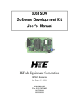
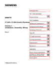
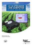
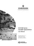
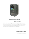
26
Chapter 3 Installation and Wiring
RS485/RS232
converter
EV 1000
Function
5V power
Transmit
Receive
Ground
RS485 port
Function
-
+
Fig. 3-12
terminal
RS485-
RS485+
Terminal
RS485-
RS485+
shielded
cable
Terminal
+ 5V
TXD
RXD
GND
●
●
Function
-
+
Sign-a
l
PE
RXD
TXD
GND
DTR
DSR
RI
CD
RTS
CTS
Pin
Enclosure
2
3
5
4
6
9
1
7
8
RS485-(RS485/RS232)-RS232 communication cable
EV1000
TDS-PA01
fieldbus
RS485 port
Func
Terminal
signal-Func
RS485-
signal+ Func
RS485+
Twisted
cable
Func
Terminal
RS485-
A
RS485+
B
Connect to
PROFIBUS
Be able to connect
1-32 RS485
EV2000
TDS-PA01
TD3000
TDS-PA01
Fig. 3-13
RS485-(TDS-PA01)-PROFIBUS Wiring Diagram
Precautions for communication port connection:
z The PE terminal of each drive should be
earthed at a nearby grounding point;
z The GND terminal of each drive should be
connected together;
z RS485 communication uses shielded cables,
which is earthed at one side. The earth wire of
the shielded cable is connected to RS485
communication module (PE).
If the above standard wiring methods cannot
meet the requirements, you can take the actions
below:
Wiring
The multi-function input terminals use full-bridge
rectifying circuit, as the below figure shows. PLC
is the common terminal for X1~X5, FWD and
REV. The PLC terminal can sink or source current.
Wire connections X1~X5, FWD and REV is
flexible and the typical wiring is shown below:
① Connection method 1
It is default to use the drive’s internal power
source 24V, i.e. PLC connected with P24.
If you want to use external power supply, make
sure to remove the wire between PLC and P24.
z Use isolated RS485 communication module;
z If the noise is transmitted through the GND
line to the drive or other devices, which
results in malfunction of them, you may
disconnect the GND lines.
4)Multi-function Input Terminal and FWD, REV
EV1000 Series General Purpose Variable Speed Drive User Manual