1
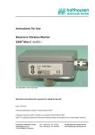
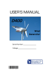
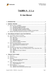
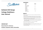
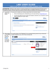
holthausen
elektronik GmbH
User Manual
Electronic Vibration Monitoring Unit
ESW®-LowCost (hol650)
date: 17.05.2007
document: hol650_hb_e.doc
technical modification possible
holthausen elektronik GmbH is certified according to DIN EN ISO 9001.
holthausen elektronik GmbH
Wevelinghoven 38
41334 Nettetal
Phone: +49 (0) 21 53 - 40 08
Fax: +49 (0) 21 53 - 89 99 4
[email protected]
www.holthausen-elektronik.de
Electronic Vibration Monitoring Unit
ESW®-LowCost (hol650)
holthausen
elektronik GmbH
Table of contents:
1. Generally basical safety-indications ..................... page 4
2. Packing and the transport .................................... page 4
3. Application............................................................ page 5
4. The solution.......................................................... page 5
5. Function ............................................................... page 6
6. Mounting of the vibration-monitoring unit ............. page 7
7. Connection of the vibration-monitoring unit .......... page 7
8. Grounding-concept ............................................... page 8
9. Limit range adjustment ......................................... page 9
10. Additional instructions .......................................... page 10
11. Mechanical data ................................................... page 11
12. Cable connection draft ......................................... page 12
Declaration of Conformity ..................................... page 13
Technical data ...................................................... Attachment
2
Electronic Vibration Monitoring Unit
ESW®-LowCost (hol650)
holthausen
elektronik GmbH
Important information
These operation instructions are to be read through completely and carefully heeded
before starting the device. Failure to heed or adhere can result in claims on
manufacturer’s liability becoming null and void for damages ensuing there from.
Manual action of any manner on the device – with the exception of proper procedures
and those described in these operation instructions – lead to forfeit of guarantee and
exclusion from liability.
The device is solely intended for the usage as described below. It is particularly not
intended for the direct or indirect protection of persons.
holthausen elektronik GmbH assumes no liability whatsoever as regards suitability for
some specific purpose.
If any question should remain open, please never hesitate to contact us.
holthausen elektronik GmbH
Wevelinghoven 38, 41334 Nettetal
Phone: +49 (0) 21 53 - 40 08, Fax: +49 (0) 21 53 - 8 99 94
Mail: [email protected]
3
Electronic Vibration Monitoring Unit
ESW®-LowCost (hol650)
holthausen
elektronik GmbH
1. Generally basical safety-indications
Don’t use this device as the only invigilator, if a malfunctioning of ESW ®-LowCost could
lead to damages on goods or Persons.
To obtain the desired result be sure, that the device with its technical data fits to the
bulk of the object you want to supervise.
The sensor is sensitive to shock. A downfall out lower height to a hard substratum can
destroy the sensor.
The assembling place and the execution of the assembling of the sensor determine
decisively the quality of the sensor signal. The assembling may only happen through
qualified and instructed persons.
The electrical hook up is to be done by instructed persons. A mistake by the connection
can entail to faulty functions, outfall or ruination of the sensor and electronics.
The ESW ®-LowCost should not be used on machines with a very energetic highfrequency solid-borne. Through resonance apparitions in the sensor, the device can
indicate a much too great or too small value.
Powerful noise sources for instance inverters, in direct closeness of the sensor,
electronics or cabling, can result in faulty behaving of the apparatus.
Potential differences and balance currents in the mass guidance can result in faulty
behaving too.
The connection cable is resistant against many but not every type of chemicals.
Through a damaged cable chemicals could get inside the unit and destroy the
electronic. Then the unit would loose their function.
Therefore the conditions from the mounting surrounding must be checked. Then the
cover material from the cable have to be proofed if it resists these requirements. You
can get an overview from the chemical resistance of the cover material from us.
2. Packing and the transport
Note:
• The sensor is sensitive to shock. A downfall out lower height to an hard
substratum can destroy the sensor.
• Avoid to kink or tie a knot in the cable.
• Keep the electronic in a dry place.
• In case of a downfall or heckling or squeezing, could the casing or the
operation elements or the board get defects.
With adequate warning-labels and through a qualified packaging and storage, you can
protect the sensor and electronics at carriage against influences from outside.
4
Electronic Vibration Monitoring Unit
ESW®-LowCost (hol650)
holthausen
elektronik GmbH
Description and operation instructions
3. Application
In all technical environments arise by different events and processes vibration. Often
they are to disregarded or even necessary, sometimes but also undesirably,
damagingly or even dangerously. This circumstance is valid basically as well as for the
frequency and the intensity of the vibration. One additional problem occurs, that such
dangerous working conditions arising in a totally unexpected manner or slowly and
secretly. Dangerous vibration can be possible on :
Ventilators, pumps and blowers
Shakes, separators
Conveyor belt- and transfer equipment
Drives
Equipment-, refinement- and production machines
The reasons for such not unacceptably available vibrations are located for example in
mechanical faulty or imbalance, among other sings initiate through overload, void
speed or contamination. Father more express in such manner also incorrect handling,
loads or adjustment. The consequence is often decreasing of production quality or
even production loss, as well imperilment of the security and damage escalation, at the
lowest one enlarged wear and tear. Increasing of automation, as well for example high
noise level, hinder often some acoustical or visible monitoring. There by offer an early
identification, material considerate treatment and damage limitation and considerable
ability for cost reduction. On the other hand must of course the expenditure for vibration
monitoring be in good relation to value of the system and also to accomplishable
amount to the related damage.
4. The solution
The electronically vibration monitoring unit ESW ®-LowCost, is special for such range of
applications developed. The unit is useful for monitoring of existing mechanical
vibrations, and during overstepping of fixed limit value usable for regulation of the
system control environment. This Device operate independently, is a compact unit
subsisting sensor and evaluation electronic, housed in a rugged aluminium case. The
unit is small and light and there fore in optimal way against environmental influences
encapsulated.
The wiring design is particularly free from interference establish. The mounting is
simple and without necessity of any special tools possible. Further maintenance work is
not necessary! Any electrician could implement the electrical connection.
In order to adjust the unit to optimum, related to the presented vibration problem is in
need measurement-, frequency range, response time respectively drop off delay time
by factory adaptable. The output of the unit is one switch contact, related to limit range
control circuits with an adjustable switch level and (or) analogue output current signal.
5
Electronic Vibration Monitoring Unit
ESW®-LowCost (hol650)
holthausen
elektronik GmbH
5. Function
Mounting of the vibration-monitoring unit is generally done on such place, where
inadmissible vibration occurs or can be expected. The unit is permanently monitoring
the real condition on the machine during the vibration. The noticed mechanical
vibration detected by the sensor is transformed to the corresponding electrical signal.
The following evaluation electronic, filter and processed measurement value in such
way, that output signal, which occurs, allows a clear and on the current situation based
opinion of the present mechanical vibration also in the critical range of the monitoring
facility.
The output signal is compared with an adjustable reference level. In case the
measured value exceed the reference level for longer than the fixed delay time range,
then alarm relay will be activated, and is used to drive any warn- or control equipment.
In case the measured value falls below of the reference level, the alarm relay will be
deactivated after fixed delay time and change the alarm status back to his standard
condition. The delay time range, during activation or deactivation of the alarm relay is
by customer request, directly by factory in a specified range adjustable.
Additional supply with alarm memory, where the unit after the activation of alarm relay
will remain in the alarm status till an external and manually reset will be activated
(option), is possible and is preferred used in such cases where the vibration monitoring
unit is on difficult accessible places mounted. Through this advanced memory function
is every alarm registered. Reset of the alarm memory, through reset button, is from any
place or location by variable mounting of one or more in parallel-connected reset
buttons possible.
Through an additional analog current output (option) is a current value for estimation
available, because this average value corresponds directly to the current vibration
situation on the measured location. This value is by any measurement instrument
visible and meets the present vibration status.
6
Electronic Vibration Monitoring Unit
ESW®-LowCost (hol650)
holthausen
elektronik GmbH
6. Mounting of the vibration monitoring unit
Attention:
Protect the ESW®-LowCost unit definitely against drop, stroke
or other mechanical shock!
Before mounting of the vibration-monitoring unit, please define the main vibration
direction and select measurement place that is as much as possible free of own
vibration and is not belonging to any noise level. The mounting place should also meet
sufficiently space to mount the unit exact to the vibration direction.
The choose of mounting place for the vibration-monitoring unit should be decided in
such manner, that later adjustment work will be accessibly assured and the unit against
distress trough climate, not belonging vibration and electrical disturbance with magnetic
or electric fields is protected.
Prepare the corresponding hole to the mounting surface, which has to be with M8thread (or M12 depended on version) prepared. Around of the mounting surface is
sufficiently large and plane place for the unit necessary that should be in vertically
manner to the mounting hole and to the direction of the vibration oriented. After the
degreased threaded bolt has been spread with a suitable thread safeguarding medium,
the device can be screwed on at the measuring place and tightened by hand as far as
possible.
After finishing of the mounting procedure the connection wire will be connected. Please
make sure that connection cable are flexible enough and on the other hand fix enough
to avoid cable own noise level, trough bump generated. Also any dangerous situation
for the user for example stumbles and fall should be prevented.
7. Connecting the vibration-monitoring unit
Attention:
All connection operations must be done only from qualified
personal and without connected power supply!
The ESW unit has standardized fixed connection wire. Alternatively is the monitoring
unit also with electrical connector available. The connection wire for connection in any
electric control box or in case requested to appropriate connection box, which should
be one suitable place fixed. The unit require stabilized power voltage of 24V DC ±10%.
The voltage should be of any oscillation or any disruption free. Please don’t place the
power line near of disruption sources like heavy power line or electronic devices.
Additional information for avoiding interference sources; see grounding and shielding
explanation described on Page 8 “Grounding-concept”.
The maximal power load on the relay contact is 30V and 1A. Please pay attention on
working manner of the relays. The description is always related to work mode where
power voltage is not activated. After switching of power supply ON, without recognition
of an alarm status is alarm relay activated. In case alarm status occurs, power failure or
connection wire to the control box is interrupted, will the connection between middle
contact and closer contact be disconnected. This circumstance allows control off
defects and failures in the connection wire as well in the monitoring unit self.
The optional analog current output could be by factory as current source of 0-20mA or
4-20mA realized. The load should not exceed more than 330Ohm.
In case the unit is equipped with alarm memory (option), additional reset button for the
unit is necessary. The reset is activated when control wire is for a short time with
ground potential connected.
7
holthausen
Electronic Vibration Monitoring Unit
ESW®-LowCost (hol650)
elektronik GmbH
8. Grounding concept
main control box
with power supply
optional
connection box
vibration
control unit
shield
shield
+Ub
-Ub
signal ground
vibration control unit ground
local
vibration control unit ground
signal ground
connection box ground
local
connection box ground
main control
box ground
local
main control box ground
In case there is explicitly isolated installation not requested, is usually through
attachment with screws each case to the local machine ground connected.
By factory side is inside of the ESW ®-LowCost unit with cable point of connection,
depended on customer needs, the shielding and / or signal ground with case potential
connected.
Connection to the local Ground
(Standard delivery condition for ESW ®-LowCost with cable is the cable shield and the
signal ground not with case of the unit connected!)
By the ESW ®-LowCost with “Tuchel” device connector could by factory, dependent on
customer request the signal ground with case potential be connected. The cable shield
could be on the customer site through the connection to the ground contact of the
connector with case ground of the unit also connected.
(By standard delivery of the unit with connector is the ground contact with the case by
mechanical contact connected and signal ground is not with case of the unit connected!)
Inside of optional plug in box could also cable shielding, box ground and signal ground
by choice and dependent on local facts and requirements be connected.
Inside of big facilities with considerable energy consumption and relevant distances
between machines could such big voltage potential differences being build up, that
substantial balancing current on the ground network will occur. Dependent on intensity
of such currents could arise any interference’s or damaging of the vibration-monitoring
unit could be the result.
Voltage potential differences could also arise on machines, with small distances not
clear crossing of ground potential for example painted colour or movable parts like
suspension mounting.
Energetic high frequency interference energy could also be to the measurement signal
wire by inductive or trough capacity coupling added and change the real existing
measurement value! In this way could for example parallel going elements act as
coupling capacity and wind grounding cable act as inductivity
Memorize: Ground is not equal everywhere!
Check the situation Plan the grounding concept Select the facility / realization
8
Electronic Vibration Monitoring Unit
ESW®-LowCost (hol650)
holthausen
elektronik GmbH
9. Limit range adjustment
One of the main goals of the unit is after exceeding of specified measurement value to
activate the alarm relay for execution of specified effects. In order that the switch level
of measurement value should meat real conditions on measurement place and should
also to the environment be adaptable, is the limit value in the unit adjustable.
For this reason is the unit equipped with step switch element with whom the limit value
between 10% and 100% of the measurement value could be fixed. This Adjustment
should be done only from qualified personal and only without connection to the power
supply. The step switch is with small screwdriver blade width 3mm adjustable. On top
of the step switch exist numbers 0 till 9. Here by means the number 1 one limit value of
10%, for example the number 6 the limit value of 60% and the number 0 means 100%
from total measurement range. The switch doesn’t have any mechanical limitation and
could be turned around 360° without any trouble.
78
23
901
456
Please take care during the adjustment, don’t use by mistake or destroy any other
adjustment elements. You should prevent absolutely entering of dirty, humidity or
another alien elements in to the housing off the unit. Make sure after finishing of the
adjustment to close the unit perfectly. Please check that the cover is in a sticky manner
closed.
9
Electronic Vibration Monitoring Unit
ESW®-LowCost (hol650)
holthausen
elektronik GmbH
10. Additional instructions
In general any maintenance on the unit is not necessary. But please check from time to
time whether the parts of vibration monitoring unit like cover, cable or extended sensor
are not loosened or damaged by vibration.
Father more should be continuously insured that no qualities of the power supply and
environmental conditions disturbance by electrical or magnetically fields and
mechanical pressure like shock and push not succeeding are changed. In such case a
new specification for the unit will be necessary.
Should be absolute unrealistic values suddenly indicated by the unit, please check first
of all the fixed mechanical conditions of the unit and then measurement place
regarding possible sources of own vibration like for example loosely parts.
In case any problems occur please contact the manufacture!
We are every time ready to help you with recommendation and support.
10
holthausen
Electronic Vibration Monitoring Unit
ESW®-LowCost (hol650)
elektronik GmbH
11. Mechanical data
Version with cable connection
90.0
93. 8
63. 5
axis
Measuring axis
Pg 16
37.2
19. 9
39.2
M8
or
M12
68.0
94. 2
Version with Tuchel device connector
93. 8
63. 5
37. 2
19. 9
39. 2
M8
or
M12
68. 0
112. 6
11
axis
Measuring axis
90. 0
holthausen
Electronic Vibration Monitoring Unit
ESW®-LowCost (hol650)
elektronik GmbH
12. Cable connection draft
Version with cable connection
ESW ®-LowCost
+24V supply volt.
ground
pink
blue
grey
white
yellow
green
brown
analog output
external reset
closer contact
middle contact
opener contact
: +24V supply voltage
: ground
: analog output
: external reset (option)
: closer contact
: middle contact
: opener contact
shield : see page 8 ´Grounding-Concept´
The outlined contacts of the alarm-relay are in position: without supply voltage.
Under normal working conditions are the closer- and middle-contacts connented.
Regulary here ends the cable shield in the housing and is isolated to the case.
Version with Tuchel device connector
ESW ®-LowCost
mechanical connection between case and
- contact
+24V supply volt.
ground
analog output
4
1
3 2
Tuchel Gerätestecker
5-polig T 3353 000
closer contact
middle contact
The outlined contacts of the alarm-relay are in position: without supply voltage.
Under normal working conditions are the closer- and middle-contacts connected.
optional could be the internal ground connected to the case
(for more information see page 8 ´Grounding Concept´ )
®
ESW is a registered trademark of holthausen elektronik GmbH, Wevelinghoven 38, 41334 Nettetal
12
Electronic Vibration Monitoring Unit
ESW®-LowCost (hol650)
holthausen
elektronik GmbH
Declaration of Conformity
Application of Directive 2004/108/EC
we hereby declare, that the construction of:
multifunctional vibration control unit for the vibration
monitoring
ESW®-LowCost (hol650)
complies to the following norms:
EN 61000 - 6 - 4
interference emissions
EN 61000 - 6 - 2
interference immunity
Manufacture
holthausen elektronik GmbH
Manufacture`s
Address
Wevelinghoven 38
D - 41334 Nettetal
Manager
Michael Holthausen
Place
Date
Nettetal
17.05.2007
Signature
_______________________
13