1
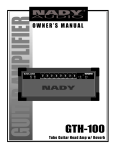
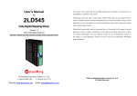
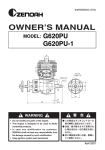
UGE-Solar Off-Grid Controller
OWNER’S MANUAL
CONTENTS
INTRODUCTION ..................................................................................................................................
3
PARTS LIST .................................................................................................................................................. 4
SPECIFICATIONS ....................................................................................................................................
5
SAFETY INSTRUCTIONS.................................................................................................................... 6-7
INSTALLATION ...................................................................................................................................
8-11
WIRING DIAGRAM ................................................................................................................................. 12
WIRING INSTRUCTIONS ................................................................................................................ 13
LCD DISPLAY ......................................................................................................................................... 14 -15
NOTES.............................................................................................................................................................. 16
TECHNICAL SUPPORT .................................................................................................................... Back
2
INTRODUCTION
Dear UGE-Fusion System Owner,
Congratulations on purchasing your UGE renewable energy solution. Welcome to our family.
Enclosed in this manual is information regarding installation, operation and maintenance of the controller. Please
read through the manual in its entirety before installing and using your fusion system and controller. Under certain
circumstances this information may not be fully comprehensive and additional instruction or information may be
required in order to successfully and safely complete the installation.
These installation and maintenance instructions contain important information for the safe installation and maintenance
of the UGE-solar off grid controller. Designed for use with the UGE-Fusion System the function of the controller is
to regulate the voltage and current coming from your solar panels to your batteries.
The controller should only be installed by qualified personnel such as an employee of a UGE Partner or a certified
electrician. Yearly maintenance checks should be performed by qualified personnel. The owner should retain a copy
of this manual for reference and to give to future maintenance personnel.
This manual should be used in conjunction with turbine installation manual, and the UGE Electrical Supplement.
These manuals can be found on the website of the tower and electronics suppliers respectively or can be provided
by your UGE Partner.
We would like to hear from you with any questions or comments that you have. Please contact us during working
hours (Monday-Friday 9:00am to 6:00 pm - US Eastern Time) at:
Telephone: +1 (917) 720-5685
Website: www.urbangreenenergy.com
Email: [email protected]
Sincerely,
3
325
PARTS LIST
Check the Charge Controller and Parts
325
Please check all the parts based on the following instructions when receiving the package. Contact your local
dealer if any part is missing.
400
x1 Controller
400mm [1’ - 153/4]
375mm [1’ - 143/4]
Charge Controller * 1
Charge Controller *130
1
130mm [0’ - 51/8]
400
200
130
x3 Cable Gland
Cable Glands *3
Cable Glands
*3
User Manual * 1
x1 User Manual
User Manual * 1
200
4
900
SPECIFICATIONS
Output Voltage .........................................................................................................................................................................48Vdc
Input Voltage Range (line to line voltage) .........................................................................................................70V/150V
Charge Start/Stop Voltage (Iine to line voltage) ..............................................................................................70V/60V
Rated Input Current ...................................................................................................................................................................30A
Converter Efficiency/MPPT Efficiency........................................................................................................ >85% / >90%
Standby Consumption ......................................................................................................................................................... <3W
Battery Floating Charge Voltage.......................................................................................................................55.2Vdc ±1V
Battery Pulse Charge (charge 1min per 10min) .................................................................................
.......57.6Vdc ±1V
Battery Low Shutdown ............................................................................................................................................46Vdc ±1V
Battery Sleep Mode Voltage ..................................................................................................................................40Vdc ±1V
Rated. Charge Current ........................................................................................................................................................ 62.5A
User Interface ........................................................................................................................................ LCD Status Indicators
Interface Enclosure......................................................................................................................................Use Terminal Block
Operating Temperature........................................................................................................... -20ºC/-4°F ~ 40ºC/104°F
Dimension (L × W × H).......................400mm x 375mm x 130mm [1’-153/4” x 1’ - 143/4” x 0’ - 51/8”]
Weight ............................................................................................................................................................................15kg /33.1Ibs
Protection Class ................................................................................................................................................. Indoor use only
5
Safety instructions
The charge controller shall be installed and operated in accordance with the instructions in this User Manual.
The following conventions are used in this guide:
WARNING
Improper handling may cause a very hazardous situation
resulting in personal injury or loss of life.
CAUTION
Warnings identify conditions or practices that could cause
personal injury or damage to the unit.
1. The PV panel is potentially dangerous when it is generating power. It is necessary
to break the connection between the charge controller and the PV panel when
installation or repair/ maintenance is conducted. Above all, do not connect the
charge controller with the PV panel under the situation that the charge controller is
not connected with the battery as doing so could cause severe damage to the charge
controller.
2. This machine includes components carrying high voltage electricity that could
potentially cause serious personal injury or even loss of life. The controller shall
only be installed by a qualified professional such as a licensed Electrician or UGE
distributor. The wiring of the controller shall meet the requirements of the NEC or
the local electrical code.
3. Install Solar Controller in dry, well ventilated space. This charge controller adopts
natural convection to disperse heat; the charge controller should not be put in the place
close to the heat resource or under direct sunlight. Keep controller away from moisture.
4. Keep the charge controller and battery away from the flammable and/or conductive
materials.
5. The weight of this controller is around 15kg / 33.1 Ibs. Always treat the charge
controller with caution during transportation and installation.
6. Do not leave any heavy item on the top of the controller.
7. If the controller behaves abnormally, disconnect the controller from the PV panels
and battery. Do not restart the controller until you have contacted UGE technical
support and the observed issue has been resolved.
8. Never operate the charge controller together with any PV panel or battery which
exceed the rated specifications of the controller. 6
Safety instructions
9. Connecting the battery cables incorrectly, such as reverse polarity, will burn
the fuse and may permanently damage the controller. 10. To reduce the chance of short-circuits, use insulated tools when installing or working
with the controller.
11. Do not remove or bypass the grounding pin. Make sure the controller enclosure is
grounded.
12. Please follow all the instructions and warning markings in this manual and on the
controller. 13. Please check the appearance of controller before installation. Contact your sales
representative if there are any obvious signs of damage.
14. The controller should be mounted vertically against a wall. Do not mount the
controller at an angle (see page 9).
15. This controller should ONLY be installed and maintained by qualified professionals
such as a certified electrician or UGE distributor. 16. Connect the wires by following the wiring instructions on page 13.
17. Follow the wiring guide provided in the wire connection diagram (see page 12).
18. When connecting the lead-acid battery, please pay great attention to the polarity.
19. Do not connect the controller to batteries that will operate in voltage ranges outside
the battery voltage ranges defined on the specifications table, page 5.
20. Please keep this manual for your future reference.
7
INSTALLATION
Step 1
Check the installation location
- minimum 20cm (8 “) clear space around the machine is required for heat dissipation
Step 2
Mount the charge controller
8
INSTALLATION
Wall
Wall
Wall
Mounting Guide
Step 2.1
Step 2.2
Step 2.3
Put the controller against the
wall and mark the locations for
drilling (6 holes).
Drill 6 holes and place anchors
into those holes.
Fasten screws and secure the
controller.
CAUTION
The mounting method
in C is prohibited.
A B
C
9
INSTALLATION
Controller Interface
Battery
Output
Terminals
Power Switch
10
PV Input Terminals
Communication
Interface
LCD Display
INSTALLATION
BAT+ Terminal
Connect to the positive
polarity of a battery.
PV+ Terminal
Connect to the
positive pole of the
solar panel cable
BAT- Terminal
Connect to the negative
polarity of a battery.
PV- Terminal
Connect to the
negative pole of the
solar panel cable
N+ and N- Terminal
Block (RS-485)
Reserved for RS-485
communication
B+ and B- Terminal Block (BAT)
B+ connects to the positive polarity of a battery
B- connects to the negative polarity of a battery
Both of them are for detecting battery voltage
11
WIRING DIAGRAM
Electrical System Overview
An example wiring diagram is shown below. Detailed wiring diagrams are available from the UGE website or your
UGE Partner to be used for installation.
TABLE A
UGE-FUSION SYSTEM
See Note 4
TABLE B
This wiring schematic for fusion is an example utilizing a UGE-4k wind turbine and 2kW solar system
AC
Disconnect
Switch 2
Solar Panels
+
+
+
+
..+
-
+
+
+
12 AWG
12 AWG
30 A
240 V AC
fused
+
18 AWG
10 AWG
Off-Grid
Solar
Charge
10 AWG
Controller
Fuse
DC
LOAD
18 AWG
DC
OR
Battery
Bank
Inverter
AC
LOAD
48V
TABLE B
AC
Disconnect
Switch 1
10 AWG
Off-Grid
Wind
Charge 10 AWG
Controller
12
14 AWG
Diversion
Load
14 AWG
18 AWG
18 AWG
18 AWG
18 AWG
60 A
240 V AC
nonfusible
Safety Brake
60 A
nonfusible
Fuse
18 AWG
Grid / Generator
Back-up
OR
See Note 5
UGE 4K
See Note 3
TABLE A
18 AWG
Notes:
1. Wire gauge recommendations based on NEC 310.16 for THHW copper wire below 100’F
(A certified electrician shall verify wire gauge meets local electrical code)
2. Each grounded component shall have its own ground wire and connect at a common
earth ground
3. Connect 14AWG wires to either 12V or 24V battery in Battery Bank
4. Voltage Drop 1.2 V (5%)
5. Project electrician to source appropriate inverter for connection of battery bank and grid or
local generator
6. For 12 AWG: maximum length is 27 feet (8.2m) for maximum voltage drop 3%
WIRING INSTRUCTIONS
This machine includes components carrying high voltage electricity that could potentially
cause serious personal injury or even loss of life. The controller shall only be installed by a
qualified professional such as a licensed Electrician or UGE distributor. The wiring of the
controller shall meet the requirements of the NEC or the local electrical code.
Before starting installation, please make sure the input and output power both are
disconnected to avoid electrical shock.
1. Ground the controller enclosure by connecting a wire from the grounding pin to an earth ground.
2. Verify the voltage of the batteries is within the normal operating range for the controller per the specs on
page 5.
3. Connect Battery cables Red 10AWG (2x) from charge controller BAT+ to battery positive pole and Black
10AWG (2x) from charge controller BAT- to battery negative pole. It is suggested that a 100A switch be added.
The cable connecting to the battery should not be longer than 5 meters [16’ – 4”].
4. Connect battery voltage sensing cables Red 18AWG and Black 18AWG from the B+ and B- directly to the
positive and negative output points of the battery bank respectively (Power-charging cable loop and sensing
loop must be separated). Take care to ensure that the battery polarity is correct.
5. Connect the positive pole and negative pole solar panel output cables 12AWG (Red/ Black) to the PV+ and
PV- terminals respectively. It is suggested that a 40A switch be added.
6. Verify again that the battery voltage is normal and that the battery voltage sensing cables are properly con
nected, then start the Charge Controller.
7. Verify that the LCD is working and the battery voltage indicated is correct.
8. Observe the status of charging the batteries on the LCD screen and verify that the batteries are being
charged.
13
LCD DISPLAY
MPPT Charging
PV: ____._V, ___ . _A
Input voltage and current from PV panels
Battery voltage and charging current
MPPT Charging
Pi _____W Po_____W
Power input and power output
14
LCD Display Operating
15
OPERATION & MAINTENANCE
1. The charge controller only requires little maintenance if it is used properly. Please periodically clean the
controller surface with wet cloth. 2. This charge controller is designed to automatically protect the battery when the battery is fully charged –
without performing the MPPT. 3. Avoid over discharging the battery to prolong the battery life. 4. Keep the solar panel clean and well maintained. 5. If the controller is behaving abnormally or displaying an error on the LCD screen, please break
off the input from the solar panel immediately, then break off the battery; do not start the charge
controller again until you have contacted your local dealer or UGE representative and the problem
has been resolved.
16
NOTES
17
TECHNICAL
SUPPORT
If your product requires troubleshooting or warranty
service, contact your merchant. If you are unable to
contact your merchant, or the merchant is unable to
provide service, contact UGE directly at:
Urban Green Energy
330 West 38th Street
Suite 1103
New York, NY 10018
Tech. Support Phone: +1 (917) 720-5685
Email: [email protected]
This manual is an adaptation of the Power General
installation manual for this product and is meant to be
used as a guideline only. For specific details, refer to the
Power General manual. A certified electrician or the
project electrician is responsible for verifying that the
controller installation meets local elelctrical code. UGE
provides this manual as a guideline and is not responsible
for any errors which may occur due to the use of this
manual.
18
August 2012
Copyright Urban Green Energy Inc. 2012