1
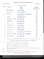
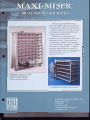
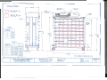
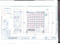
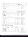
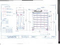
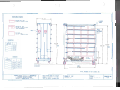
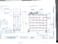
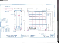
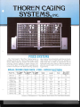
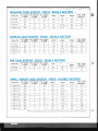
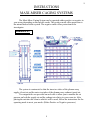
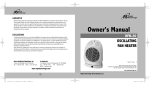
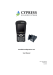
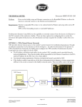
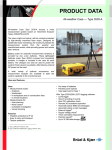
MANUAL
MAXI-MISER CAGING SYSTEMS
Page
Introduction and air flow
1–2
Positive operation – product protection
3
Negative operation – people protection
4
Trouble shooting
5
How often to wash
6
Hepa filter / Blower module
7
Washing and Autoclaving
8
How to clean the Hepa filter / Blower module
9
Hybrid transition with optional exhaust fan
10-11
Autoclaving
12-13
Cage Sizes
14
Cage Materials
15
Air Exchange Rate
16
Thoren Caging Systems , Inc.
815 West Seventh St.
P.O.Box 586
Hazleton, PA 18201-0586
Phone 570-455-5041
Fax 570-454-3500
Lithgow Laboratory Services
8414 W. Farm Rd #180-225
Las Vegas, NV 89131
Phone 702-413-0832
Fax 702-363-4981
1
INSTRUCTIONS
MAXI-MISER CAGING SYSTEMS
The Maxi-Miser Caging System can be operated wither positive or negative to
your room, depending on our specific needs. The positive mode offers protection to
the animal housed in the system. The negative mode offers protection to the
investigator.
DRAWING #1
The system is constructed so that the inner two tubes of the plenum carry
supply (clean) air and the outer two tubes of the plenum carry exhaust (spent) air.
Two magnehelics are provided on each rack to allow you to monitor the air
pressure on both the supply air and the exhaust air relative to your room air. After
placing the unit into the room in which it will be used, follow the instructions for the
operating mode to meet your needs. (Either Positive or Negative pressures.)
1
2
Each shelf is divided into three separate compartments. The inner section is the supply
( clean ) duct. The outer two sections are the exhaust ( spent ) ducts. ( See drawing # 2
above )
In each cage position there is an orifice hole for the supply and an orifice hole for the
exhaust air . ( See drawing #3 below
D d D R A W IN G # 3
2
3
POSITIVE OPERATION - Product Protection
1. Zero the magnehelic gauges. (This must be done before the rack is running.) To do
this, set the indicating needle exactly at the zero mark, using the zero adjust screw on
the cover at the bottom of the magnehelic. (A small, straight blade screw driver works
best.)
Note: In the United States you will connect to a 110 volt, 60 hertz, single phase
receptacle, capable of providing 4 amperes. In the United Kingdom and other
European Countries, you will connect to a 240 volt, 50 hertz, single phase
receptacle, capable of providing 4 amperes.
3. To adjust the supply air, adjust the damper for the supply air until the supply
magnehelic reads .30 inches of water column.
4 To adjust the exhaust air adjust the damper for the exhaust air until the exhaust
3
4
NEGATIVE OPERATION -People Protection
1. Zero the magnehelic gauges. (This must be done before the rack is running.) To do
this, set the indicating needle exactly at the zero mark, using the zero adjust screw on the
cover at the bottom of the magnehelic. (A small, straight blade screw driver works best.)
2. Connect the rack to the air source. The air source may be the central Heating, Air
Conditioning, and Ventilating System (HVAC)(Option 6), the HEPA Filter/Blower
Module(Option 5), or the Hybrid Transition (Option 7). Make certain that the flexible hoses are
securely fastened to the hose connections with a stainless steel hose clamp. Insert the electrical
plug into the wall receptacle, the units %vill be running as soon as the electrical connection is
made.
3. To adjust the supply air, adjust the damper for the supply air until the supply
magnehelic reads .20 inches of water column.
4. To adjust the exhaust air, adjust the damper for the exhaust air until the exhaust
magnehelic reads .30 inches of water column.
5. Allow the system to stabilize for twelve hours before introducing animals into the system.
4
5
TROUBLE SHOOTING
1. If you do not get sufficient static pressure on either the supply or the exhaust,
check the following:
a. Make sure that the black rubber plugs on the ends of all the shelves are in place.
b. Be sure that the plates on the top and the bottom of the plenum are closed and
clamped in place.
c. Check to be sure that the HEPA filters are securely tightened down with the four
jack screws, which seal the fan transition to the HEPA Filter gasket.
d. Check to be sure that the HEPA Filter/Blower Module Cover Plates are securely
fastened.
e. Check the hoses for tears or air leaks.
2. Do not under any circumstances adjust the air static pressure by turning the
adjustment screw on the magnehelic.
3. If your unit is equipped with automatic watering, make certain that your bedding is of
sufficient size, so that the rodents cannot stuff it into the valves. Also check your valves
to assure that they are adjusted to the proper flow rate. (Contact the automatic watering
manufacturer for this information. Edstrom Industries -(414) 534-5181. SE Lab Group (513) 451-0530.)
Thoren Caging Service# :
(570) 455-5041
5
6
HOW OFTEN TO WASH?
The question of how often to wash the Maxi-Miser Caging System is one
that is often asked. The question of tear-down and thorough cleaning has
become a matter of personal preference. The actual air supply and exhaust
ducts are internal surfaces, which do not come in contact with ambient room
air. These internal surfaces can be cultured on a weekly basis to determine the
necessity for total tear down. The outer surfaces of the rack should be wiped
down every time the cage is changed with a commercially available sterilant of
your choice. When the cage has been removed from the system, the shelf area
above that cage should be disinfected, as well as, the shelf area below the cage.
Keep in mind that even stainless steel may be attacked by either strongly acidic
or strongly alkaline compounds.
6
7
HEPA FILTER/BLOWER MODULE
FREESTANDING, TOP MOUNTED, BOTTOM MOUNTED
The HEPA Filter/Blower Module is the unit which contains HEPA Filters for
both the supply air and the exhaust air. The service time of the filters depends on the
cleanliness of the air source. When a filter becomes dirty, you will notice a pressure
drop on your magnehelic gauge. You may compensate by opening the dampers on both
the supply and the exhaust to maintain your static pressure, but we recommend that
you replace your filters as soon as an uncorrectable pressure drop is detected. The
Prefilters should be visually inspected on a weekly basis for dirt and clogging. By
maintaining the Prefilters in good condition, you will substantially extend the life of
your HEPA filters. HEPA Filters usually last five to six years, if the Prefilters have
been maintained.
The HEPA Filter/Blower Module is actually two completely separate unit. Each
unit has a refilter, fan, and a HEPA Filter. The actual assembly drawings for each
unit are attached. The Top Mounted and Bottom Mounted Supply Module is Drawing
Number 3000-1. The Exhaust Module for these units is Drawing Number 3000-2. The
Free Standing Module is Drawing Number 3002.
The prefilters are accessible by removing the small prefilter Cover plate from
the units and sliding the prefilter out. The prefilters in the Top Mounted and Bottom
Mounted Modules are washable and autoclavable. The prefilters in the Free Standing
Module are disposable.
The HEPA Filters and the fans are accessible by removing the cover plates on
both boxes. This is accomplished by removing the wing nuts (in the E.C. these are cap
nuts) from the box. To remove the HEPA filters you must remove the cover plates, then
loosen the four wing nuts which hold the fan in compression with the HEPA Filter.
There are two wing nuts at the top of the filter and two at the bottom. When the four
wing nuts are loose, slide the fan and fan transition (as one unit) out of the box and
then remove the HEPA Filter. Reverse the procedure to reassemble, always making
sure that the air flow direction and HEPA Filter direction are correct. (Air flow
direction is away from the fan; HEPA Filter separators should be vertical.)
Always change the prefilter when changing HEPA cartridges. We recommend
washing the HEPA Filter/Blower Module when changing HEPA Filters. To wash
the units you must remove the electrical box by removing the four screws that
hold it in place, the prefilter, the HEPA Filter, and the fan, mounted on the fan
transition. The Module then can be washed and autoclaved.
7
8
WASHING and AUTOCLAVING
The Maxi-Miser Caging System can be washed and autoclaved with the
exception of the Magnehelic Gauges, the fans, the prefilters ( in the free standing
module and the Hybrid Supply Module), the HEPA filters, and the electrical
components.
I.
To wash the Maxi-Miser Caging System unplug the system and remove the air
source from the rack.
2.
As with any caging system, the cages, cage covers, filter covers, water bottles
and cardholders should be removed and washed as separate items.
3.
4.
5.
The magnehelic Gauges are not washable and must be removed from the plenum.
This is easily done by removing the nut and lock washer from the stem of the
magnehelic, which holds it in place in the plenum. The supply magnehelic gauge
and the exhaust
magnehelic gauge have the stem fitting in different ports, you will not be able
to put the gauges back improperly, as the stems will not line up with the holes
in the plenum.
Each shelf of the system is held in place with two red or gray handled clamps, these
clamps must be opened and the shelf removed from the rack for thorough
cleaning. The red shelf gasket and the black shelf plug should be removed from the
shelf and can be washed separately. The shelf can now be placed in a washer to be
sanitized. For ease of handling, a Shelf Wash Rack is available to handle nine
shelves, nine gaskets, and nine plugs.
The rack plenum has a clean-out plate on the bottom which is held in place with
clamps, this plate must be opened to allow cleaning. Racks with free-standing
HEPA Filter/Blower Modules or bottom-mounted HEPA Filter/Blower Modules
will have a clean-out plate on
the top as well, this must also be opened. The structural frame (consisting of the
main air plenum, the ladder frame, the stringers, and the bottom frame with
8
9
How to wash the HEPA Filter/Blower Module:
1.
Unplug the unit and disconnect the hoses which connect the unit to the rack.
2.
Remove the two prefilters using the access panels on the unit.
3.
Remove the main access panels from the module using the wing nuts (cap nuts in E.C.)
4.
Loosen the four wing nuts that hold the fan transition in compression with the
HEPA Filter in both the Supply Box and the Exhaust Box.
5.
Unplug the fans and slide the fans, attached to the fan transitions, out of the boxes.
6.
Remove the HEPA Filters from the units and discard of them properly.
7.
Remove the electrical boxes from the modules by taking out the four screws that hold
them in place.
8.
You may now wash and autoclave the stainless steel enclosures.
9.
When totally dry, reassemble the unit by reversing the steps listed above. Be sure that the
HEPA Filters are placed in their proper operating position (check air flow direction and
make sure that the proper side is up). Make sure that the four wing nuts seal the fan
transition to the HEPA Filter are securely fastened. Reassemble the cover plates making
sure that the proper plate is on the proper box. Test the filter seals with DOP.
9
10
HYBRID TRANSITION WITH OPTIONAL EXHAUST FAN
The Hybrid Transition consists of a HEPA Filtered Supply Module, which is
mounted on top of the rack, and a Transition, which allows you to connect the Supply
Module to the Rack Supply and the Rack Exhaust to the central Heating, Air
Conditioning, and Ventilating (HVAC) System. Both components of the Hybrid
Transition are constructed of stainless steel and can be washed and autoclaved. The
Hybrid Supply Module is shown in Drawing Number 3005-1. The optional Exhaust
Fan Booster is shown in Drawing 3005-2.
The HEPA Filtered Supply Module contains a prefilter, a fan, and a 12"x 12"x
11-1/2" HEPA Filter. The prefilter for the Supply Module is 12"x 12"x 2" and is
located at the back of the unit. The prefilter is accessible by loosening the wing nut on
the retainer bar and swinging the bar upward. The prefilter should be visually
inspected every week for signs of clogging. By maintaining the prefilter in good
condition, you will substantially extend the life of the HEPA Filter. The HEPA Filter
and fan are accessible by removing the cover plate from the top of the module. To
remove the HEPA Filter you must remove the cover plate, then remove the four wing
nuts that hold the fan in compression with the HEPA Filter. Slide the fan, attached to
the fan transition, away from the HEPA Filter and remove it from the module. Then
slide the HEPA Filter away from the threaded rods which hold it in place and remove
it from the module. Reverse the procedure to reassemble, always making sure that the
air flow direction and HEPA Filter direction are correct. (Air flow is away from the
fan; HEPA Filter separators should be vertical.
Always change the prefilter when changing the HEPA cartridge. We
recommend washing the HEPA Filtered Supply Module when changing the HEPA
Filter.
To wash the HEPA Filtered Supply Module
1.
Unplug the unit from the wall receptacle and disconnect the hose which connects
the unit to the transition. If you have the optional Exhaust Fan Booster or the
alarm unplug these as well.
2.
Remove the prefilter by swinging the retainer bar, which holds the prefilter in place,
upward.
3.
Remove the cover plate from the top of the unit by using the wing nuts.
4.
Remove the four wing nuts from the threaded rod that holds the fan in
compression with the HEPA Filter.
5.
Unplug the fan and slide the fan, attached to the fan transition, out of the
module.
10
11
6.
Remove the HEPA Filter from the unit and discard of it properly.
7.
Remove the electrical box, containing the circuit breakers, from the side of the
module, by removing the four screws that secure it to the module.
8.
You may now wash and autoclave the stainless steel box enclosure.
9.
When totally dry, reassemble the unit by reversing the steps listed above. Be sure
that the HEPA Filters are placed in their proper operating position (check air flow
direction and make sure that the proper side is up). Make sure that the four wing
nuts that seal
the fan transition to the HEPA Filter are tightened. Test the filter seal with DOP.
The transition which allows you to connect the Supply Module to the Rack Supply
and the Exhaust to the central HVAC, can be removed from the rack by unlatching the
two clamps, which hold it in place. If you have the optional Exhaust Fan Booster on your
unit, you must remove this from the transition by using the four hex head bolts, which
hold it in place.
11
12
AUTOCLAVING
The Maxi-Miser Caging System can be autoclaved, each component of the system
will be listed separately with instructions to help you to autoclave them most effectively.
The Maxi-Miser Rack - is constructed from stainless steel and can be autoclaved with
the exception of the magnehelic gauges. The magnehelic gauges can easily be removed
by loosening the nut from the stem that holds the gauge to the plenum. To thoroughly
clean the rack, the rack should be disassembled per the instructions on rack washing.
The Air Sources (HEPA Filter/Blower Modules, Transitions and Hybrid Transitions) are constructed from stainless steel and can be autoclaved, but you must first remove
the prefilters, the HEPA Filters, and the electrical components. Please follow the
instructions for each particular piece of equipment for disassembly and cleaning.
Cages - the standard Thoren cage is molded from high heat polycarbonate, which is
autoclavable at 270° F. Polycarbonate (Lexan or Makrolon) has an autoclave life of
approximately twenty cycles at 250° F. High Heat Polycarbonate (PPC or APEC) is
autoclavable to 270° F and has an autoclavable life of approximately fifty cycles. Ultem or
PSF have an autoclave life of hundreds of cycles at 270° F and are a better choice for
facilities who must autoclave on a weekly or biweekly basis. To maximize the performance
of your plastic cages it is best to use as short an autoclave cycle as possible. Cages to be
autoclaved should not be subjected to mechanical loading during sterilization.(Mechanical
Loading is stacking cage set-ups on top of one another so that the bottom cage has
excessive weight on it.) The quality of the steam provided to the autoclave is important to
the success of the autoclave cycle. Chemicals present in the steam (ie. water conditioning
additives and boiler additives) can attack your plastic cages causing premature cage failure.
Soap residue or chemical residue on cages which are autoclaved will also cause premature
failure, as the autoclave accentuates the action of these incompatible materials on the cage
and will cause cracking, crazing, and discoloration. The practice of placing bedding into the
cages to be autoclaved can be detrimental to the cage, as some beddings, when autoclaved,
release chemicals which attack the resin. The practice of marking cages with a marker can
also be detrimental to cages, many markers contain solvent which chemically attacks resins.
12
13
Stainless Steel Cardholders - are constructed from stainless steel and can be
autoclaved. Two types of cardholders are available either the hoof; for use with
punched cards or a vertical/horizontal cardholder for use with 3"x 5" cards. Thoren
also offers molded cardholders manufactured from the same resins as the cage. The
plastic cardholders are attached to the cage and can be washed and autoclaved
following the same protocol as the cages.
Stainless Steel Cage Covers - are constructed from stainless steel wire bar and can
be autoclaved with no problems. The Thoren Cage Covers have a few unique
Bottles - are molded from glass, high heat polycarbonate, or PSF and can be
autoclaved with the exception of the "drilled" glass bottle. If you want to use the
"drilled" bottles and must autoclave, the polycarbonate or PSF bottles are the
bottles to use. Thoren offers a variety of stoppers (neoprene or silicone), stainless
steel caps, or plastic disposable caps for the bottles. The stoppers are washable and
autoclavable, as are the stainless steel cap. The plastic disposable caps can be
washed. but not autoclaved.
features - every Thoren cover has a tag bar/handle so that the cover can be handled
from the top without ever touching the underside of the cover. The Bottle Covers
have a grommet which protects the stopper or cap from the rodent's gnawing. All
Thoren Cage Covers have dimpled panels to allow thorough cleaning.
13
14
14
THOREN CAGING SYSTEMS,
INC. 815 West Seventh Street
P.O. Box 581
Hazleton, Pennsylvania, USA 18201
Air Exchange Rate Information
Thoren Caging Systems, Inc. utilizes the Bruel and Kjaer 7620 to measure the decay of a tracer
gas in the cage. We measure the concentration levels of sulfur hexafluoride tracer gas at
various static pressures that the Maxi- Miser Caging System normally operates at.
The graph above represents the actual readings from the BK 7620 and the air exchange rate
in cage changes per hour at specific pressures in inches of water column.
Average Cage Air Exchange Rate For Mouse # 9 Cage
Cage Air Exchanges Per Hour
90
Magnehelic
Gauge
Readings
80
70
60
50
40
30
20
10
0
OFF
OFF
.10
.05
.15
.10
.20
.15
.25
.20
.30
.25
.35
.30
Recommended
Setting
.40
.35
.45
.40
.50 Supply
.45 Exhaust