1
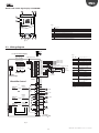
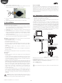
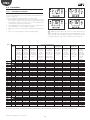
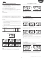
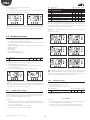
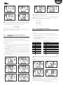
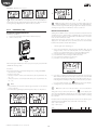
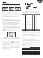
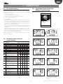
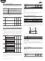
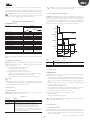
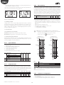
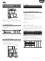
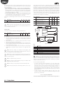
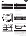
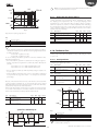
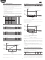
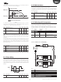
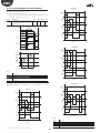
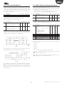
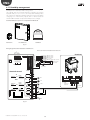
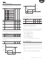
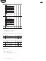
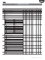
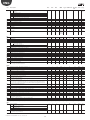
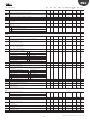
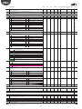
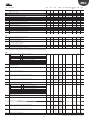
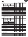
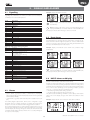
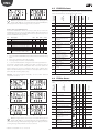
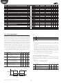
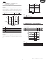
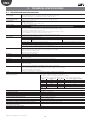
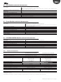
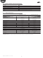
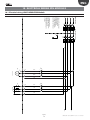
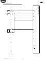
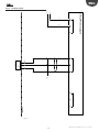
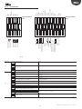
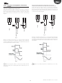
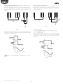
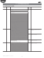
ENG
6.8.2
Par.
d3
d4
d5
d8
dpr
Other defrost parameters
Description
Defrost activation delay
Defrost at start-up
0/1=No/Yes
Defrost delay at start-up
High temperature alarm delay after
defrost (and door open)
Defrost priority over continuos cycle
0/1=No/Yes
Def
0
0
Min
0
0
Max U.o.M.
250 min
1
-
0
1
0
0
250
250
min
hour
OFF
0
0
1
-
ON
ON
CMP
F0=0
Evap. fan
• d3 determines the time that must elapse, when the defrost is activated,
PWM mod.
between the stopping of the compressor (electric heater defrost) or
the starting of the compressor (hot gas defrost), and the activation of
the defrost relays on the main and auxiliary evaporators. In the hot gas
defrost, the delay d3 is useful for ensuring a sufficient amount of hot
gas before activation of the hot gas valve;
• d4 determines whether to activate or not the defrost at the controller
start-up. The defrost at start-up request has priority over the activation
of the compressor and the continuous cycle. Force a defrost at
controller start-up may be useful in special situations.
Sd
Sv-F1
(Sv-F1)-Frd
ON
F0=1
Evap. fan
Example: frequent power drops inside the plant. In case of lack of voltage
the tool resets the inner clock that calculates the period of time between
two defrosts, starting from zero. If, in an extreme case, the frequency of
the power failure were greater than the defrost frequency (e.g. a power
failure every 8 hours, against a defrost every 10 hours) the controller
would never perform a defrost. In a situation of this type, it is preferable
to activate defrost on start-up, above all if the defrost is controlled by
temperature (probe on the evaporator), therefore avoiding unnecessary
defrosts or at least reducing the running times. In the case of systems
with a large number of units, if selecting defrosts at start-up, after a power
failure all the units will start defrosting, thus causing a voltage overload.
This can cause power overload. To overcome this, the parameter d5 can
be used. It adds a delay before the defrost, and this delay must obviously
be different for each unit.
• d5 represents the time that elapses between the start of the controller
and the start of the defrost at start-up;
• dd is used to force the stop of the compressor and the evaporator fan
after a defrost cycle in order to facilitate the evaporator dripping;
• d8 indicates the time of exclusion of the high temperature alarm
signalling from the end of a defrost;
• if dpr = 0, the defrost and the cycle have the same priority; if dpr = 1,
if the continuous cycle is in progress and a defrost request intervenes,
the continuous cycle ends and the defrost starts.
PWM mod.
Fig. 6.n
Key
CMP
PWM mod.
F1
Frd
Evap.fan
t
Sv
Sd
Compressor
PWM modulation
Fan activation threshold
Fan activation differential
Evaporator fan
Time
Virtual probe
Defrost probe
The fan can be stopped:
• when the compressor is off (parameter F2);
• during defrost (parameter F3).
6.9.2
Variable speed fans
The installation of variable speed fans may be useful to optimise energy
consumption. In this case, the fans are powered by the mains, while the
control signal is provided by UltraCella by analogue output Y1 0…10 Vdc.
The maximum and minimum fan speed can be set using F6 and F7
parameters (in percentage respect range 0…10V). If using the fan speed
controller, F5 represents the temperature below which the fans are
activated, with a fix hysteresis of 1°C.
6.9 Evaporator Fans
6.9.1
Par.
F5
Fixed speed fans
F6
F7
The status of the fans depends on the compressor status.
When the compressor is:
• on: the fan can also be on (F0=0) or activated based on the evaporator
temperature, virtual probe Sv, based on the formula:
Par.
F0
Description
Evaporator fans management
…
2 = variable speed fans
HO1 Output Y1 0…10 V configuration
…
2 = variable speed fans regulated on Sd
• off: the fan is controlled by a PWM that has duty cycle with a fixed
period of 60 minutes.
duty_cycle = F2
60
UltraCella +0300083EN - rel. 1.6 - 31.10.2015
Def
0
Min
0
Max U.o.M.
2
-
5
30
0
-50
0
0
200
60
3
Def
15
Min
-50
100
0
F7
0
Max U.o.M.
200 °C/°F
100
F6
%
%
To enable the algorithm, it’s necessary to select variable speed fans mode
(F0=2) and set analogue output 0…10 Vdc (HO1=2).
if Sd ≤ (Sv - F1) -Frd --> FAN = ON
if Sd ≥ (Sv - F1)
--> FAN = OFF
Par. Description
F0
Evaporator fan management
0 = always on with compressor on
1= activation depends on Sd, Sv
F1
Fan activation temperature
F2
Fan activation time with CMP off
HO1 Output Y1 configuration
0 = not active
Description
Evaporator fans cut-off temperature
(hysteresis 1°C)
Maximum fans speed
Minimum fans speed
°C/°F
min
-
50
Def
0
Min
0
0
0
Max U.o.M.
2
-
3
-