1
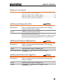
Programmable DC Power Supply
PSU Series
PROGRAMMING MANUAL
Revision 1.4 October 2015
ISO-9001 CERTIFIED MANUFACTURER
This manual contains proprietary information, which is protected by
copyright. All rights are reserved. No part of this manual may be
photocopied, reproduced or translated to another language without
prior written consent of Good Will company.
The information in this manual was correct at the time of printing.
However, Good Will continues to improve products and reserves the
rights to change specification, equipment, and maintenance
procedures at any time without notice.
Good Will Instrument Co., Ltd.
No. 7-1, Jhongsing Rd., Tucheng Dist., New Taipei City 236, Taiwan.
Table of Contents
Table of Contents
SAFETY INSTRUCTIONS ................................................... 4
GETTING STARTED ........................................................... 8
PSU Series Overview .............................. 9
Appearance .......................................... 13
Configuration Settings ......................... 21
REMOTE CONTROL ........................................................ 30
Interface Configuration ........................ 31
Command Syntax ................................. 55
Command List ..................................... 58
Status Register Overview ................... 113
Error List ........................................... 124
APPENDIX ..................................................................... 133
PSU Default Settings ......................... 133
Error Messages & Messages .............. 135
LED ASCII Table Character Set ........... 136
INDEX............................................................................ 137
3
PSU Programming Manual
SAFETY INSTRUCTIONS
This chapter contains important safety
instructions that you must follow during
operation and storage. Read the following before
any operation to insure your safety and to keep
the instrument in the best possible condition.
Safety Symbols
These safety symbols may appear in this manual or on the
instrument.
WARNING
Warning: Identifies conditions or practices that
could result in injury or loss of life.
CAUTION
Caution: Identifies conditions or practices that
could result in damage to the PSU or to other
properties.
DANGER High Voltage
Attention Refer to the Manual
Protective Conductor Terminal
Earth (ground) Terminal
4
SAFETY INSTRUCTIONS
Do not dispose electronic equipment as unsorted
municipal waste. Please use a separate collection
facility or contact the supplier from which this
instrument was purchased.
Safety Guidelines
General
Guideline
CAUTION
Do not place any heavy object on the PSU.
Avoid severe impact or rough handling that
leads to damaging the PSU.
Do not discharge static electricity to the PSU.
Use only mating connectors, not bare wires, for
the terminals.
Do not block the cooling fan opening.
Do not disassemble the PSU unless you are
qualified.
(Measurement categories) EN61010-1:2010 and EN61010-2-030
specifies the measurement categories and their requirements as
follows. The PSU falls under category II.
Measurement category IV is for measurement performed at the
source of low-voltage installation.
Measurement category III is for measurement performed in the
building installation.
Measurement category II is for measurement performed on the
circuits directly connected to the low voltage installation.
0 is for measurements performed on circuits not directly
connected to Mains.
Power Supply
WARNING
AC Input voltage range: 85Vac~265Vac
Frequency: 47Hz to 63Hz
To avoid electrical shock connect the protective
grounding conductor of the AC power cord to
an earth ground.
5
PSU Programming Manual
Cleaning the PSU
Operation
Environment
Disconnect the power cord before cleaning.
Use a soft cloth dampened in a solution of mild
detergent and water. Do not spray any liquid.
Do not use chemicals containing harsh material
such as benzene, toluene, xylene, and acetone.
Location: Indoor, no direct sunlight, dust free,
almost non-conductive pollution (Note below)
Relative Humidity: 20%~ 85% (no condensation)
Altitude: < 2000m
Temperature: 0°C to 50°C
(Pollution Degree) EN61010-1:2010 and EN61010-2-030 specifies
the pollution degrees and their requirements as follows. The PSU
falls under degree 2.
Pollution refers to “addition of foreign matter, solid, liquid, or
gaseous (ionized gases), that may produce a reduction of dielectric
strength or surface resistivity”.
Pollution degree 1: No pollution or only dry, non-conductive
pollution occurs. The pollution has no influence.
Pollution degree 2: Normally only non-conductive pollution
occurs. Occasionally, however, a temporary conductivity caused
by condensation must be expected.
Pollution degree 3: Conductive pollution occurs, or dry, nonconductive pollution occurs which becomes conductive due to
condensation which is expected. In such conditions, equipment
is normally protected against exposure to direct sunlight,
precipitation, and full wind pressure, but neither temperature
nor humidity is controlled.
Storage
environment
Disposal
6
Location: Indoor
Temperature: -25°C to 70°C
Relative Humidity: ≤90%(no condensation)
Do not dispose this instrument as unsorted
municipal waste. Please use a separate collection
facility or contact the supplier from which this
instrument was purchased. Please make sure
discarded electrical waste is properly recycled to
reduce environmental impact.
SAFETY INSTRUCTIONS
Power cord for the United Kingdom
When using the power supply in the United Kingdom, make sure
the power cord meets the following safety instructions.
NOTE: This lead/appliance must only be wired by competent persons
WARNING: THIS APPLIANCE MUST BE EARTHED
IMPORTANT: The wires in this lead are coloured in accordance with the
following code:
Green/ Yellow:
Earth
Blue:
Neutral
Brown:
Live (Phase)
As the colours of the wires in main leads may not correspond with
the coloured marking identified in your plug/appliance, proceed
as follows:
The wire which is coloured Green & Yellow must be connected to
the Earth terminal marked with either the letter E, the earth symbol
or coloured Green/Green & Yellow.
The wire which is coloured Blue must be connected to the terminal
which is marked with the letter N or coloured Blue or Black.
The wire which is coloured Brown must be connected to the
terminal marked with the letter L or P or coloured Brown or Red.
If in doubt, consult the instructions provided with the equipment
or contact the supplier.
This cable/appliance should be protected by a suitably rated and
approved HBC mains fuse: refer to the rating information on the
equipment and/or user instructions for details. As a guide, a cable
of 0.75mm2 should be protected by a 3A or 5A fuse. Larger
conductors would normally require 13A types, depending on the
connection method used.
Any exposed wiring from a cable, plug or connection that is
engaged in a live socket is extremely hazardous. If a cable or plug is
deemed hazardous, turn off the mains power and remove the cable,
any fuses and fuse assemblies. All hazardous wiring must be
immediately destroyed and replaced in accordance to the above
standard.
7
PSU Programming Manual
GETTING STARTED
This chapter describes the power supply in a
nutshell, including its main features and front /
rear panel introduction. After going through the
overview, please read the theory of operation to
become familiar with the operating modes,
protection modes and other safety considerations.
GETTING STARTED ........................................................... 8
PSU Series Overview ......................................................... 9
Series lineup .............................................................................. 9
Main Features ......................................................................... 10
Accessories ............................................................................. 11
Appearance ..................................................................... 13
PSU Series Front Panel ......................................................... 13
PSU Series Display and Operation Panel ........................... 16
Rear Panel ............................................................................... 18
Configuration Settings..................................................... 21
8
GETTING STARTED
PSU Series Overview
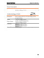
Series lineup
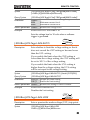
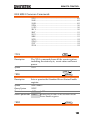
The PSU series consists of 5 models, covering a number of different
current, voltage and power capacities:
Model name
Voltage Rating1
Current Rating2
Power
PSU 6-200
6V
200A
1200W
PSU 12.5-120
12.5V
120A
1500W
PSU 20-76
20V
76A
1520W
PSU 40-38
40V
38A
1520W
PSU 60-25
60V
25A
1500W
1Minimum
voltage guaranteed to 0.2% of rating voltage.
2Minimum
current guaranteed to 0.4% of rating current.
9
PSU Programming Manual
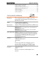
Main Features
Performance
Features
Interface
10
High power density: 1500W in 1U
Universal input voltage 85~265Vac, continuous
operation.
Output voltage up to 60V, current up to 200A.
Active power factor correction.
Parallel master/slave operation with active
current sharing.
Remote sensing to compensate for voltage drop
in load leads.
19" rack mounted ATE applications.
A built-in Web server.
OVP, OCP and OHP protection.
Preset memory function.
Adjustable voltage and current slew rates.
Bleeder circuit ON/OFF setting.
CV, CC priority start function. (prevents
overshoot with output ON)
Supports test scripts.
Built-in RS-232/485, LAN and USB interface.
Analog output programming and monitoring.
Optional interfaces: GPIB, Isolated Voltage (05V/0-10V) and Isolated Current (4-20mA)
programming and monitoring interface.
(Factory options)
GETTING STARTED
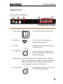
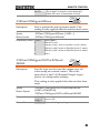
Accessories
Before using the PSU power supply unit, check the package
contents to make sure all the standard accessories are included.
Standard
Part number
Accessories
Description
Qty.
Output terminal cover
1
Analog connector plug kit
1
Output terminal M8 bolt set
1
Input terminal cover
1
62SB-8K0HD101
1U Handle, ROHS
2
62SB-8K0HP101
1U BRACKET (LEFT), RoHS
1
62SB-8K0HP201
1U BRACKET (RIGHT), RoHS
1
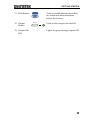
CD ROM
User manual, Programming
manual
1 set
Quick start guide
1
82SU-062H0K01
Packing list
82GW-00000C01
* CTC GW/INSTEK JAPAN
USE ,RoHS
Factory Installed
Options
1
Part number
Description
PSU-GPIB
GPIB interface
PSU-ISO-V
Voltage programming isolated
analog interface
PSU-ISO-I
Current programming isolated
analog interface
11
PSU Programming Manual
Optional
Part number
Accessories
Download
Other
Description
PSU-01C
Cable for 2 units of PSU-Series in
parallel mode connection
PSU-01B
Bus Bar for 2 units of PSU-Series in
parallel mode connection
PSU-02C
Cable for 3 units of PSU-Series in
parallel mode connection
PSU-02B
Bus Bar for 3 units of PSU-Series in
parallel mode connection
PSU-03C
Cable for 4 units of PSU-Series in
parallel mode connection
PSU-03B
Bus Bar for 4 units of PSU-Series in
parallel mode connection
PSU-232
RS232 cable with DB9 connector kit
PSU-485
RS485 cable with DB9 connector kit
GRM-001
Rack-mount slides (General Devices
P/N: C-300-S-116-RH-LH)
GTL-246
USB Cable 2.0-A-B Type, Approx. 1.2M
GPW-001
Power Cord SJT 12AWG/3C, 3m MAX
Length, 105 ºC, RNB5-5*3P UL/CSA
type
GPW-002
Power Cord H05W-F 1.5mm2/3C, 3m
MAX Length, 105 ºC, RNB5-5*3P VDE
type
GPW-003
Power Cord VCTF 3.5mm2/3C, 3m
MAX Length, 105 ºC, RNB5-5*3P PSE
type
Name
Description
psu_cdc.inf
PSU USB driver
Name
Description
Certificate of traceable calibration
12
GETTING STARTED
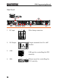
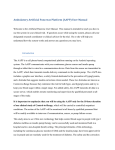
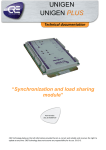
Appearance
PSU Series Front Panel
1
2
3
4
PSU 40-38
5
Display Area
Voltage
DC Power Supply
Current
CV
CC
0 - 40 V / 0 - 38A
V
A
VOLTAGE
VSR
LAN
RMT
CURRENT
ERR
DLY
ALM
ISR
Lock/ Local
PROT
Function
Test
Set
Unlock
ALM_CLR
M1
M2
M3
M1
M2
Shift
M3
RUN
Output
: Long Push
6
7
8
9 10 11 12 13
1.
Power Switch
Used to turn the power on/off.
2.
USB A Port
USB A port for data transfer,
loading test scripts etc.
3.
Air Inlet
Air inlet for cooling the inside of
the PSU series.
Voltage
4.
Voltage Knob
Used to set the voltage value or
select a parameter number in the
Function settings.
Display Area The display area shows setting values, output
values and parameter settings. The function LEDs
below show the current status and mode of the
power supply. See page 16 for details.
5.
Current Knob
Current
Displays the current or the value
of a Function parameter.
13
PSU Programming Manual
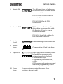
6.
Lock/Local
Button
Lock/Local
Unlock
(Long push) Used to unlock the
front panel buttons.
Unlock
Button
7.
PROT Button
Used to lock all front panel
buttons other than the Output
Button or it switches to local
mode.
PROT
Used to set and display OVP, OCP
and UVL.
ALM_CLR
(Long push) Used to release
protection functions that have
been activated.
ALM_CLR
Button
8.
Function
Button
Function
Used to configure the various
function.
M1
(+Shift) Used to recall the M1
setup.
(+Shift and hold) Used to save the
current setup to M1.
M1 Button
9.
Test Button
TEST
Used to run customized scripts for
testing.
M2
(+Shift) Used to recall the M2
setup.
(+Shift and hold) Used to save the
current setup to M2.
M2 Button
10. Set Button
SET
Used to set and confirm the output
voltage and output current.
M3
M3 Button
14
(+Shift) Used to recall the M3
setup.
(+Shift and hold) Used to save the
current setup to M3.
GETTING STARTED
11. Shift Button
12. Output
Button
13. Output ON
LED
Shift
Output
Used to enable the functions that
are written in blue characters
below the button.
Used to turn output on and off.
Lights in green during output ON.
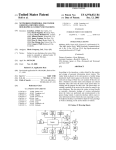
15
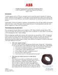
PSU Programming Manual
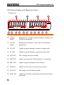
PSU Series Display and Operation Panel
Display Area
14
16
15
17
CV
CC
V
A
VOLTAGE
VSR
18
LAN
19
CURRENT
RMT
20
ERR
21
DLY
22
ALM
23
ISR
24
M1
25
M2
26
M3
27
RUN
28
14. Voltage
Meter
Displays the voltage or the parameter number of a
Function parameter.
15. Current
Meter
Displays the current or the value of a Function
parameter.
16. CV LED
Lights in green during constant voltage mode.
17. CC LED
Lights in green during constant current mode.
18. VSR LED
The voltage slew rate enable.
19. LAN LED
Lights up when the LAN interface is connected.
20. RMT LED
Lights in green during remote control.
21. ERR LED
Lights in red when an error has occurred.
22. DLY LED
The output on/off delay enable.
23. ALM LED
Lights in red when a protection function has been
activated.
16
GETTING STARTED
24. ISR LED
The current slew rate enable.
25. M1 LED
Lights in green when the memory value are being
recalled or saved.
26. M2 LED
Lights in green when the memory value are being
recalled or saved.
27. M3 LED
Lights in green when the memory value are being
recalled or saved.
28. RUN LED
Auto sequence has been activated.
Note
Only the ERR and ALM LED’s are red. All the
others are green.
17
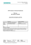
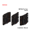
PSU Programming Manual
Rear Panel
1
2
ISOLATED PROGRAMMING
4 - 20mA
3 4 5 6 7 8
1
2
ISOLATED PROGRAMMING
0 - 5V / 0 - 10V
3 4 5 6 7 8
9
10
DC OUTPUT
ANALOG PROGRAMMING
S
LS NC
REMOTE SENSE
8
1.
RS 485 / 232
L
N
LAN
LS S
OUT
7
AC Input
IN
AC INPUT
6 5
L
4 3
2
1
Wire clamp connector.
N
AC INPUT
2.
DC Output
3.
USB
4.
LAN
18
Output terminals for 6V to 60V
models.
USB port for controlling the PSU
remotely.
RS 485 / 232
LAN
Ethernet port for controlling the
PSU remotely.
GETTING STARTED
5.
RS 485 / 232
Remote-IN
LAN
Two different types of cables can
be used for RS232 or RS485-based
remote control.
PSU-232: RS232 cable with DB9
connector kit.
PSU-485: RS485 with DB9
connector kit.
6.
RS 485 / 232
Remote-OUT
LAN
RJ-45 connector that is used to
daisy chain power supplies with
the Remote-IN port to form a
communication bus.
PSU-485S: Serial link cable with
RJ-45 shielded connector.
7.
Analog
Control
8.
Remote
Sense
ANALOG PROGRAMMING
External analog control connector.
S
LS NC
LS
S
Compensation of load wire drop.
REMOTE SENSE
9.
Option Slot
1
10. Ground
Screw
2
ISOLATED PROGRAMMING
0 - 5V / 0 - 10V
3 4 5 6 7 8
Blank sub-plate for standard units.
Isolated Analog connector for
units equipped with Isolated
Current and Voltage
Programming and Monitoring
option.
GPIB connector for units equipped
with IEEE programming option.
Connector for grounding the output (two
positions, shown in red).
19
PSU Programming Manual
DC OUTPUT
RS 485 / 232
OUT
L
N
LAN
IN
AC INPUT
20
GETTING STARTED
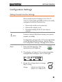
Configuration Settings
Setting Normal Function Settings
The normal function settings, F-01~F-61, F70~F-76, F-88~F-89 and F100~F122 can be easily
configured with the Function key.
Ensure the load is not connected.
Ensure the output is off.
Function settings F-90~97 can only be
viewed.
Note
Function setting F-89 (Show Version) can only be
viewed, not edited.
Configuration settings F-90~ F-97 cannot be edited
in the Normal Function Settings. Use the Power
On Configuration Settings. See page 23 for details.
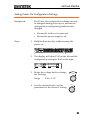
Steps
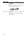
1. Press the Function key. The
function key will light up.
Function
2. The display will show F-01 on the left and the
configuration setting for F-01 on the right.
CV
CC
V
A
VOLTAGE
VSR
LAN
RMT
CURRENT
ERR
DLY
ALM
ISR
M1
M2
M3
RUN
3. Rotate the voltage knob to change
the F setting.
Range
Voltage
F-00~F-61, F-70~F-76,
F-88~F-97, F100~F122
21
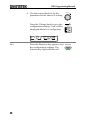
PSU Programming Manual
4. Use the current knob to set the
parameter for the chosen F setting.
Press the Voltage knob to save the
configuration setting. ConF will be
displayed when it is configuring.
CV
Exit
22
LAN
RMT
Voltage
CC
V
A
VOLTAGE
VSR
Current
CURRENT
ERR
DLY
ALM
ISR
M1
M2
M3
RUN
Press the Function key again to exit
the configuration settings. The
function key light will turn off.
Function
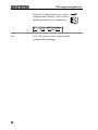
GETTING STARTED
Setting Power On Configuration Settings
Background
The Power On configuration settings can only
be changed during power up to prevent the
configuration settings being inadvertently
changed.
Ensure the load is not connected.
Ensure the power supply is off.
Steps
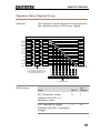
1. Hold the Function key whilst turning the
power on.
Voltage
DC Power Supply
PSU 40-38
Current
CV
CC
0 - 40V / 0 - 38A
V
A
VOLTAGE
VSR
LAN
RMT
CURRENT
ERR
DLY
ALM
ISR
M1
Lock/Local
PROT
Function
Test
Set
Unlock
ALM_CLR
M1
M2
M3
M2
Shift
M3
RUN
Output
: Long Push
2. The display will show F-90 on the left and the
configuration setting for F-90 on the right.
CV
CC
V
A
VOLTAGE
VSR
LAN
RMT
CURRENT
ERR
DLY
ALM
ISR
M1
M2
M3
RUN
3. Rotate the voltage knob to change
the F setting.
Range
Voltage
F-90 ~ F-97
4. Use the current knob to set the
parameter for the chosen F setting.
Current
23
PSU Programming Manual
Press the Voltage knob to save the
configuration setting. ConF will be
displayed when it is configuring.
CV
CC
V
A
VOLTAGE
VSR
Exit
24
LAN
RMT
CURRENT
ERR
DLY
ALM
ISR
M1
M2
M3
RUN
Cycle the power to save and exit the
configuration settings.
Voltage
GETTING STARTED
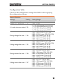
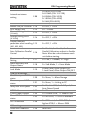
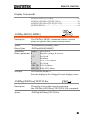
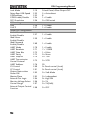
Configuration Table
Please use the configuration settings listed below when applying
the configuration settings.
Normal Function
Settings
Output ON delay time
Output OFF delay time
Setting
F-01
F-02
V-I mode slew rate select F-03
Setting Range
0.00s~99.99s
0.00s~99.99s
0 = CV high speed priority (CVHS)
1 = CC high speed priority (CCHS)
2 = CV slew rate priority (CVLS)
3 = CC slew rate priority (CVLS)
F-04
0.001~0.06V/msec (PSU 6-200)
0.001~0.125V/msec (PSU 12.5-120)
0.001~0.2V/msec (PSU 20-76)
0.001~0.4V/msec (PSU 40-38)
0.001~0.6V/msec (PSU 60-25)
Falling voltage slew rate F-05
0.001~0.06V/msec (PSU 6-200)
0.001~0.125V/msec (PSU 12.5-120)
0.001~0.2V/msec (PSU 20-76)
0.001~0.4V/msec (PSU 40-38)
0.001~0.6V/msec (PSU 60-25)
Rising current slew rate
F-06
0.001~2A/msec (PSU 6-200)
0.001~1.2A/msec (PSU 12.5-120)
0.001~0.76A/msec (PSU 20-76)
0.001~0.38A/msec (PSU 40-38)
0.001~0.25A/msec (PSU 60-25)
Falling current slew rate F-07
0.001~2A/msec (PSU 6-200)
0.001~1.2A/msec (PSU 12.5-120)
0.001~0.76A/msec (PSU 20-76)
0.001~0.38A/msec (PSU 40-38)
0.001~0.25A/msec (PSU 60-25)
Rising voltage slew rate
25
PSU Programming Manual
Internal resistance
setting
Bleeder circuit control
Buzzer ON/OFF control
OCP Delay Time
Current Setting Limit
(I-Limit)
Voltage Setting Limit
(V-Limit)
Display memory
parameter when recalling
(M1, M2, M3)
F-09
F-10
F-12
0~0.03Ω (PSU 6-200)
0~0.104Ω (PSU 12.5-120)
0~0.263Ω (PSU 20-76)
0~1.053Ω (PSU 40-38)
0~2.4Ω (PSU 60-25)
0 = OFF, 1 = ON, 2 = AUTO
0 = OFF, 1 = ON
0.1 ~ 2.0 sec
F-13
0 = OFF, 1 = ON
F-14
0 = OFF, 1 = ON
F-15
0 = OFF, 1 = ON
F-08
Auto Calibration Parallel
F-16
Control
Measurement Average
Setting
Alarm Recovery and
Output Status
Lock Mode
USB/GPIB settings
Show front panel USB
status
Show rear panel USB
status
0 = Disable, 1 = Enable, 2 = Execute
Parallel Calibration and set to Enable.
Note: Must be a short between each
unit before starting.
F-17
0 = Low, 1 = Middle, 2 = High
F-18
0 = Safe Mode, 1 = Force Mode
F-19
0:Lock Panel, Allow Output OFF
1:Lock Panel, Allow Output ON/OFF
F-20
0 = None, 1 = Mass Storage
F-21
0 = None, 1 = Linking to PC
Setup rear USB Speed
F-22
GPIB Address
GPIB Enable/Disable
Show GPIB available
status
F-23
F-24
0 = Disable USB, 1 = Full Speed, 2 =
Auto Detect Speed
0 ~ 30
0 = Disable GPIB, 1 = Enable GPIB
F-25
0 = No GPIB, 1 = GPIB is available
SCPI Emulation
F-26
0 = GW Instek, 1 = TDK GEN, 2 =
Agilent 5700, 3 = Kikusui PWX
LAN settings
Show MAC Address-1
F-30
0x00~0xFF
26
GETTING STARTED
Show MAC Address-2
Show MAC Address-3
Show MAC Address-4
Show MAC Address-5
Show MAC Address-6
LAN Enable
DHCP
IP Address-1
IP Address-2
IP Address-3
IP Address-4
Subnet Mask-1
Subnet Mask-2
Subnet Mask-3
Subnet Mask-4
Gateway-1
Gateway-2
Gateway-3
Gateway-4
DNS address -1
DNS address -2
DNS address-3
DNS address-4
Socket Server
Enable/Disable
Show Socket Server Port
Web Server
Enable/Disable
Web Password
Enable/Disable
Web Enter Password
UART Settings
F-31
F-32
F-33
F-34
F-35
F-36
F-37
F-39
F-40
F-41
F-42
F-43
F-44
F-45
F-46
F-47
F-48
F-49
F-50
F-51
F-52
F-53
F-54
UART Mode
F-70
UART Baud Rate
F-71
UART Data Bits
UART Parity
UART Stop Bit
F-72
F-73
F-74
F-57
F-58
F-59
F-60
F-61
0x00~0xFF
0x00~0xFF
0x00~0xFF
0x00~0xFF
0x00~0xFF
0 = OFF, 1 = ON
0 = OFF, 1 = ON
000~255
000~255
000~255
000~255
000~255
000~255
000~255
0~255
0~255
0~255
0~255
0~255
0~255
0~255
0~255
0~255
0 = Disable, 1 = Enable
No setting
0 = Disable, 1 = Enable
0 = Disable, 1 = Enable
0000~9999
0 = Disable UART, 1 = RS232,
2 = RS485
0 = 1200, 1 = 2400, 2 = 4800,
3 = 9600, 4 = 19200, 5 = 38400,
6 = 57600, 7 = 115200
0 = 7 bits, 1 = 8 bits
0 = None, 1 = Odd, 2 = Even
0 = 1 Bit, 1 = 2 Bits
27
PSU Programming Manual
UART TCP
F-75
UART Address (For TDK) F-76
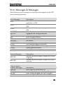
System Settings
Factory Set Value
F-88
Show Version
F-89
0 = SCPI, 1 = TDK (emulation mode)
00 ~ 30
0 = None
1 = Return to factory default settings
0, 1 = Version
2, 3, 4, 5 = Build date (YYYYMMDD)
6, 7 = Keyboard CPLD
8, 9 = Analog Board CPLD
A, B = Analog Board FPGA
C, D, E, F = Kernel Build
(YYYYMMDD)
G, H = Test Command Version
I, J, K, L = Test Command Build
(YYYYMMDD)
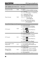
Power On Configuration Settings*
CV Control
F-90
CC Control
F-91
Output Status when
Power ON
F-92
Master/Slave
Configuration
F-93
External Output Logic
F-94
28
0 = Control by Local
1 = Control by External Voltage
2 = Control by External Resistor Rising
3 = Control by External Resistor Falling
4 = Control by Isolated Board
0 = Control by Local
1 = Control by External Voltage
2 = Control by External Resistor Rising
3 = Control by External Resistor Falling
4 = Control by Isolated Board
0 = Safe Mode (Always OFF),
1 = Force Mode (Always ON),
2 = Auto Mode (Status before last
time power OFF)
0 = Independent
1 = Master with 1 slave in parallel
2 = Master with 2 slaves in parallel
3 = Master with 3 slaves in parallel
4 = Slave (parallel)
0 = High ON, 1 = Low ON
GETTING STARTED
Monitor Voltage Select F-96
0 = 5V , 1 = 10V
Control Range
F-97
0 = 5V [5kΩ], 1 = 10V [10kΩ]
External Output Control
F-98
0 = OFF, 1 = ON
Function
Trigger Input and Output Configuration Settings
Trigger Input Pulse
0~60ms. 0 = trigger controlled by
F100
Width
trigger level.
0 = None
1 = Output ON/OFF (refer to F103)
Trigger Input Action
F101
2 = Setting (refer to F104 & F105)
3 = Memory (refer to F106)
Output State When
0 = OFF
F103
Receiving Trigger
1 = ON
Apply Voltage Setting on
0 ~ rated voltage (only applicable
F104
Trigger
when F101 =2)
Apply Current Setting on
0 ~ rated current (only applicable
F105
Trigger
when F101 =2)
Recall memory number F106
1 ~ 3 (M1 ~ M3)
Trigger Output Pulse
0 ~ 60ms. 0 = trigger output is set to
F120
Width
the active level, not pulse width.
Trigger Output Level
F121
0 = LOW, 1 = HIGH (if F120 = 0)
0 = None
1 = Switching the output on or off
Trigger Source
F122
2 = Changing a setting
3 = Recalling a memory
Special Function Settings*
Calibration
F-00
0000 ~ 9999
*Note
Power On configuration settings can only be set
during power up. They can, however, be viewed
under normal operation.
29
PSU Programming Manual
REMOTE CONTROL
This chapter describes basic configuration of
IEEE488.2 based remote control.
Interface Configuration ................................................... 31
Command Syntax ............................................................ 55
Command List ................................................................. 58
Status Register Overview ................................................ 112
Error List ........................................................................ 124
30
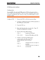
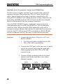
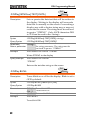
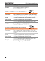
REMOTE CONTROL
Interface Configuration
USB Remote Interface
Configuration
USB
Configuration
Steps
PC side
connector
Type A, host
PSU side
connector
Rear panel Type B, slave
Speed
1.1/2.0 (full speed/high speed)
USB Class
CDC (communications device
class)
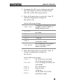
1. Connect the USB cable to the rear
panel USB B port.
2. Change the Rear panel-USB (F-22) Page 21
setting to 2 (Auto Detect Speed) or
1 (USB Full Speed).
Note
If you are not using the rear panel
USB device port, set F-22 to 0
(Disable USB).
Page 21
3. The RMT indicator will turn on when a remote
connection has been established.
CV
CC
V
A
VOLTAGE
VSR
LAN
RMT
CURRENT
ERR
DLY
ALM
ISR
M1
M2
M3
RUN
RMT indicator
31
PSU Programming Manual
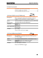
Function Check
Functionality
check
Invoke a terminal application such as Realterm.
To check the COM port No., see the Device
Manager in the PC. For WinXP; Control panel
→ System → Hardware tab.
Run this query command via the terminal
application after the instrument has been
configured for USB remote control (page 31).
*idn?
This should return the Manufacturer, Model
number, Serial number, and Firmware version
in the following format.
GW-INSTEK,PSU40-38,TW123456,T0.01.12345678
Manufacturer: GW-INSTEK
Model number : PSU40-38
Serial number : TW123456
Firmware version : T0.01.12345678
32
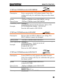
REMOTE CONTROL
GPIB Remote Interface
Configuration
To use GPIB, the optional GPIB option (GW Instek part number:
PSU-GPIB) must be installed. This is a factory installed option and
cannot be installed by the end-user. Only one GPIB address can be
used at a time.
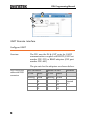
Configure GPIB
1. Ensure the PSU is off before proceeding.
2. Connect a GPIB cable from a GPIB controller to
the GPIB port on the PSU.
3. Turn the PSU on.
4. Press the Function key to enter the Page 21
Normal configuration settings.
5. Set the following GPIB settings.
F-24 = 1
Enable the GPIB port
F-23 = 0~30
Set the GPIB address (0~30)
6. Check to see that the GPIB option
is detected by the PSU. The F-25
setting indicates the GPIB port
status.
Indicates that the GPIB port is
F-25 = 1
available.
Indicates that the GPIB port is
F-25 = 0
not detected.
33
PSU Programming Manual
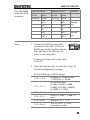
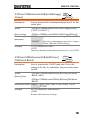
7. The RMT indicator will turn on when a remote
connection has been established.
CV
CC
V
A
VOLTAGE
VSR
LAN
RMT
CURRENT
ERR
DLY
ALM
ISR
M1
M2
M3
RUN
RMT indicator
GPIB constraints
Maximum 15 devices altogether, 20m cable
length, 2m between each device
Unique address assigned to each device
At least 2/3 of the devices turned On
No loop or parallel connection
GPIB Function Check
Background
To test the GPIB functionality, National
Instruments Measurement and Automation
Explorer can be used. This program is available
on the NI website, www.ni.com., via a search
for the VISA Run-time Engine page, or
“downloads” at the following URL,
http://www.ni.com/visa/
Requirements
Operating System: Windows XP, 7, 8
34
REMOTE CONTROL
Functionality
check
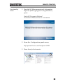
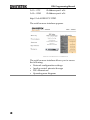
1. Start the NI Measurement and Automation
Explorer (MAX) program. Using Windows,
press:
Start>All Programs>National
Instruments>Measurement & Automation
2. From the Configuration panel access;
My System>Devices and Interfaces>GPIB
3. Press Scan for Instruments.
3
2
35
PSU Programming Manual
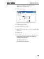
4. Select the device (GPIB address of PSU) that
now appears in the System>Devices and
Interfaces > GPIB-USB-HS “GPIBX” node.
5. Click on the VISA Properties tab on the bottom.
6. Click Open Visa Test Panel.
6
4
5
7. Click on Configuration.
8. Click on the GPIB Settings tab and confirm that
the GPIB settings are correct.
7
8
9. Click on the I/O Settings tab.
10. Make sure the Enable Termination Character
36
REMOTE CONTROL
check box is checked, and the terminal
character is \n (Value: xA).
11. Click Apply Changes.
9
10
11
12. Click on Input/Output.
13. Click on the Basic/IO tab.
14. Enter *IDN? in the Select or Enter Command drop
down box.
15. Click Query.
16. The *IDN? query will return the Manufacturer,
model name, serial number and firmware
version in the dialog box.
GW-INSTEK,PSU40-38,
TW123456,T0.02.20131205
37
PSU Programming Manual
12
13
14
15
16
UART Remote Interface
Configure UART
The PSU uses the IN & OUT ports for UART
communication coupled with RS232 (GW Part
number PSU-232) or RS485 adapters (GW part
number PSU-485)
Overview
The pin outs for the adapters are shown below.
PSU-232 RS232
cable with DB9
connector
38
DB-9 Connector
Remote IN Port
Pin No.
Pin No.
Name
Remarks
Name
Housing Shield
Housing Shield
2
RX
7
TX
3
TX
8
RX
5
SG
1
SG
Twisted
pair
REMOTE CONTROL
PSU-485 RS485
cable with DB9
connector
Steps
DB-9 Connector
Remote IN Port
Pin No.
Pin No.
Name
Remarks
Name
Housing Shield
Housing Shield
9
TXD -
6
RXD -
8
TXD +
3
RXD +
1
SG
1
SG
5
RXD -
5
TXD -
4
RXD +
4
TXD +
1. Connect the RS232 serial cable
(included in the PSU-232 kit) or
RS485 serial cable (included in the
PSU-485 kit) to the (Remote IN
port) on the rear panel.
Twisted
pair
Twisted
pair
RS 485 / 232
Connect the other end of the cable
to the PC.
2. Press the Function key to enter the Page 21
Normal configuration settings.
Set the following UART settings:
Interface: 0= Disable UART,
F-70 = 1 or 2
1= RS232 or 2 = RS485
Set the baud rate:
0=1200, 1=2400, 2=4800,
F-71 = 0 ~ 7
3=9600, 4=19200, 5=38400,
6=57600, 7=115200
F-72 = 0 or 1
Data bits: 0=7 or 1=8
Parity: 0 = none, 1 = odd, 2 =
F-73 = 0 ~3
even
F-74 = 0 or 1
Stop bits: 0 = 1, 1 = 2
TCP: 0 = SCPI, 1 = TDK
F-75 = 0 or 1
(emulation mode)
39
PSU Programming Manual
UART address if TDK is selected
for F-75.
F-76 = 00~30
3. The RMT indicator will turn on when a remote
connection has been established.
CV
CC
V
A
VOLTAGE
VSR
LAN
RMT
CURRENT
ERR
DLY
ALM
ISR
M1
M2
M3
RUN
RMT indicator
Note
40
If TDK (emulation mode) is selected for F-75, the
TDK GENESYS legacy commands should be used
for remote commands. See the TDK Genesys user
manual for details.
REMOTE CONTROL
UART Function Check
Functionality
check
Invoke a terminal application such as Realterm.
To check the COM port No, see the Device
Manager in the PC. For WinXP; Control panel
→ System → Hardware tab.
Run this query command via the terminal
application after the instrument has been
configured for either RS232 or RS485 remote
control (page 38).
*idn?
This should return the Manufacturer, Model
number, Serial number, and Firmware version
in the following format:
GW-INSTEK,PSU40-38,TW123456,T0.01.12345678
Manufacturer: GW-INSTEK
Model number : PSU40-38
Serial number : TW123456
Firmware version : T0.01.12345678
41
PSU Programming Manual
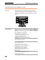
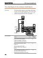
Multiple Unit Connection Using Local RS485 Bus
The PSU power supplies can have up to 31 units daisy-chained
together using the 8 pin connectors (IN OUT ports) on the rear
panel. The first unit in the chain is remotely connected to a PC
using RS232 or RS485. Each subsequent unit is daisy-chained to the
next using an RS485 local bus. The OUT port on the last terminal
must be terminated by the end terminal connector.
Only the TDK GENESYS legacy commands can be used when
using multiple units over the local RS485 bus, SCPI commands
cannot be used. When using the TDK commands, each unit is
assigned a unique address and can then be individually controlled
from the host PC. When using SCPI commands via RS232/RS485,
remote commands can only be used to control the master unit.
Operation
1. Connect the first unit’s IN port to a PC via
RS232 or RS485.
Use the serial cables supplied in the PSU232 or PSU-485 connection kit.
2. Connect the OUT port on the first unit to the IN
port of the second unit using the serial link
cable supplied in the PSU-232 or PSU-485
connection kit.
3. Connect all the remaining units in the same
fashion until all the units have been daisychained together.
Unit #N
Unit #2
RS 485 / 232
OUT
End terminal
connector
42
Unit #1
RS 485 / 232
IN
OUT
Serial link
cable
RS 485 / 232
IN
OUT
Serial link
cable
IN
To PC
RS232/RS485
serial cable
REMOTE CONTROL
4. Terminate the OUT port of the last unit with
the end terminal connector included in the
PSU-232 or PSU-485 connection kit.
5. Press the Function key to enter the Page 21
Normal configuration settings for
the master unit.
Set the following settings:
Configure the master unit as you
F-70 = 1 or 2
normally would for RS232 or
RS485 remote control.
Set the baud rate (set all units
F-71 = 0~7
the same).
F-72 = 1
Set to 8 data bits.
F-73 = 0
Parity to none.
F-74 = 1
1 Stop bit.
Set the UART TCP to TDK
F-75 = 1
(emulation mode).
Set the address of the master
F-76 = 00~30
unit. It must be a unique
address identifier.
6. Press the Function key to enter the Page 21
Normal configuration settings for
the slave(s).
Set the following settings:
F-70 = 2
Set the slave unit to RS485.
Set the baud rate (make all
F-71 = 0~7
units, including the master, the
same baud).
F-72 = 1
Set to 8 data bits.
F-73 = 0
Parity to none.
F-74 = 1
1 Stop bit.
Set the UART TCP to TDK
F-75 = 1
(emulation mode).
43
PSU Programming Manual
F-76 = 00~30
Set the address of each slave to
a unique address identifier
7. Multiple units can now be operated at the same
time, see the function check below for usage
details.
Serial link cable
with RJ-45
shielded
connectors from
PSU-232 or PSU485 connection
kit
8 Pin Connector (IN)
8 Pin Connector (OUT)
Pin No.
Name
Pin No.
Name
Housing
Shield
Housing
Shield
1
SG
1
SG
6
TXD -
6
TXD -
3
TXD +
3
TXD +
5
RXD -
5
RXD -
4
RXD +
4
RXD +
Multi-Unit Function Check
Functionality
check
Invoke a terminal application such as Realterm.
To check the COM port No, see the Device
Manager in the PC. For WinXP; Control panel
→ System → Hardware tab.
Below shows an example using the TDK
GENESYS legacy commands.
TDK Query
44
When using the TDK GENESYS legacy
commands, each unit can be individually
controlled using the unique address identifiers.
For this function check, we will assume that the
master unit is assigned to address 8, while a
slave is assigned address 11.
REMOTE CONTROL
Run this query command via the terminal
application after the instruments have been
configured for multi-unit control. See page 42.
ADR 8
IDN?
The identity string for the Master unit will be
returned:
GW-INSTEK,PSU40-38,,T0.01.12345678
Type the following:
ADR 11
IDN?
The identity string for the slave with address 11
will be returned:
GW-INSTEK,PSU40-38,,T0.01.12345678
Note: TDK commands do not use LF (line feed)
codes to terminate commands. See the TDK
Genesys user manual for further information.
45
PSU Programming Manual
Configure Ethernet Connection
The Ethernet interface can be configured for a number of different
applications. Ethernet can be configured for basic remote control or
monitoring using a web server or it can be configured as a socket
server.
The PSU series supports both DHCP connections so the instrument
can be automatically connected to an existing network or
alternatively, network settings can be manually configured.
Ethernet
configuration
Parameters
For details on how to configure the Ethernet
settings, please see the configuration chapter on
page 21.
MAC Address
(display only)
LAN Enable/Disable
DHCP
Enable/Disable
IP Address
Subnet Mask
Gateway
DNS Address
Sockets Server
Enable/Disable
Web Server
Enable/Disable
Web Password
Enable/Disable
Web Enter Password
Web Server Configuration
Configuration
This configuration example will configure the
PSU as a web server and use DHCP to
automatically assign an IP address to the PSU.
1. Connect an Ethernet cable from the
network to the rear panel Ethernet
port.
46
LAN
REMOTE CONTROL
2. Press the Function key to enter the Page 21
Normal configuration settings.
Set the following LAN settings:
F-36 = 1
Turn LAN on
F-37 = 1
Enable DHCP
F-59 = 1
Turn the web server on
F-60 = 0 or 1
Set to 0 to disable web
password, set to 1 to enable web
password
F-61 = 0000
Set the web password
~9999
3. The LAN indicator will turn on when a
network cable is plugged in.
CV
CC
V
A
VOLTAGE
VSR
LAN
RMT
CURRENT
ERR
DLY
ALM
ISR
M1
M2
M3
RUN
LAN indicator
Note
It may be necessary to cycle the power or refresh
the web browser to connect to a network.
Web Server Remote Control Function Check
Functionality
check
Enter the IP address of the power supply in a
web browser after the instrument has been
configured as a web server (page 46).
The web server allows you to monitor the
function settings of the PSU.
You can check the IP address by checking F-39 to
F-42.
F-39 = AAA
IP Address part 1 of 4
F-40 = BBB
IP Address part 2 of 4
47
PSU Programming Manual
F-41 = CCC
F-42 = DDD
IP Address part 3 of 4
IP Address part 4 of 4
http:// AAA.BBB.CCC.DDD
The web browser interface appears.
The web browser interface allows you to access
the following:
Network configuration settings
Analog control pinouts & usage
PSU dimensions
Operating area diagram
48
REMOTE CONTROL
Sockets Server Configuration
Configuration
This configuration example will configure the
PSU socket server.
The following configuration settings will
manually assign the PSU an IP address and
enable the socket server. The socket server port
number is fixed at 2268.
1. Connect an Ethernet cable from the
network to the rear panel Ethernet
port.
LAN
2. Press the Function key to enter the Page 21
Normal configuration settings.
Set the following LAN settings:
F-36 = 1
Enable LAN
F-37 = 0
Disable DHCP
F-39 = 172
IP Address part 1 of 4
F-40 = 16
IP Address part 2 of 4
F-41 = 5
IP Address part 3 of 4
F-42 = 133
IP Address part 4 of 4
F-43 = 255
Subnet Mask part 1 of 4
F-44 = 255
Subnet Mask part 2 of 4
F-45 = 128
Subnet Mask part 3 of 4
F-46 = 0
Subnet Mask part 4 of 4
F-43 = 172
Gateway part 1 of 4
F-44 = 16
Gateway part 2 of 4
F-45 = 21
Gateway part 3 of 4
F-46 = 101
Gateway part 4 of 4
F-57 = 1
Enable Sockets
49
PSU Programming Manual
Socket Server Function Check
Background
To test the socket server functionality, National
Instruments Measurement and Automation
Explorer can be used. This program is available
on the NI website, www.ni.com., via a search
for the VISA Run-time Engine page, or
“downloads” at the following URL,
http://www.ni.com/visa/
Requirements
Operating System: Windows XP, 7, 8
Functionality
check
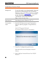
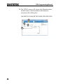
1. Start the NI Measurement and Automation
Explorer (MAX) program. Using Windows,
press:
Start>All Programs>National
Instruments>Measurement & Automation
2. From the Configuration panel access;
My System>Devices and Interfaces>Network
Devices
3. Press Add New Network Device>Visa TCP/IP
Resource…
50
REMOTE CONTROL
3
2
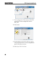
4. Select Manual Entry of Raw Socket from the
popup window.
4
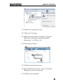
5. Enter the IP address and the port number of the
PSU. The port number is fixed at 2268.
6. Click the Validate button.
7. A popup will appear if a connection is
successfully established.
8. Click Next.
51
PSU Programming Manual
7
5
6
8
9. Next configure the Alias (name) of the PSU
connection. In this example the Alias is:
PSU_DC1
10. Click finish.
9
10
11. The IP address of the PSU will now appear
under Network Devices in the configuration
panel. Select this icon now.
12. Click Open VISA Test Panel.
52
REMOTE CONTROL
12
11
13. Click the Configuration icon,
14. Click on I/O Settings.
15. Make sure the Enable Termination Character
check box is checked, and the terminal
character is \n (Value: xA).
16. Click Apply Changes.
13
14
15
16
17. Click the Input/Output icon.
18. Enter *IDN? in the Select or Enter Command
dialog box if it is not already.
19. Click the Query button.
53
PSU Programming Manual
20. The *IDN? query will return the Manufacturer,
model name, serial number and firmware
version in the dialog box.
GW-INSTEK,PSU40-38,TW123456,T0.02.20131205
17
18
19
20
54
REMOTE CONTROL
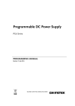
Command Syntax
Compatible
Standard
Command
Structure
IEEE488.2
Partial compatibility
SCPI, 1999
Partial compatibility
SCPI commands follow a tree-like structure,
organized into nodes. Each level of the
command tree is a node. Each keyword in a
SCPI command represents each node in the
command tree. Each keyword (node) of a SCPI
command is separated by a colon (:).
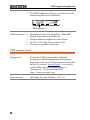
For example, the diagram below shows an SCPI
sub-structure and a command example.
MEASure
MEASure:SCALar:CURRent:DC?
SCALar
Command types
VOLTage
CURRent
POWer
DC
DC
DC
There are a number of different instrument
commands and queries. A command sends
instructions or data to the unit and a query
receives data or status information from the
unit.
Command types
Simple
A single command
with/without a parameter
Example
*IDN?
55
PSU Programming Manual
Query
A query is a simple or
compound command
followed by a question mark
(?). A parameter (data) is
returned.
Example
meas:curr:dc?
Compound
Two or more commands on
the same command line.
Compound commands are
separated with either a semicolon (;) or a semi-colon and a
colon (;:).
A semi-colon is used to join
two related commands, with
the caveat that the last
command must begin at the
last node of the first
command.
A semi-colon and colon are
used to combine two
commands from different
nodes.
Example
56
meas:volt:dc?;:meas:curr:dc?
REMOTE CONTROL
Command Forms
Commands and queries have two different
forms, long and short. The command syntax is
written with the short form of the command in
capitals and the remainder (long form) in lower
case.
The commands can be written in capitals or
lower-case, just so long as the short or long
forms are complete. An incomplete command
will not be recognized.
Below are examples of correctly written
commands.
STATus:OPERation:NTRansition?
Long
form
STATUS:OPERATION:NTRANSITION?
status:operation:ntransition?
STAT:OPER:NTR?
Short
form
stat:oper:ntr?
Square Brackets
Commands that contain square brackets
indicate that the contents are optional. The
function of the command is the same with or
without the square bracketed items, as shown
below.
Both “DISPlay:MENU[:NAME]?” and
“DISPlay:MENU?” are both valid forms.
Command
Format
APPLY
1
1.5,5.2
2 34 5
1.
2.
3.
4.
5.
Parameters
Command header
Space
Parameter 1
Comma (no space
before/after comma)
Parameter 2
Type
Description
Example
<Boolean>
Boolean logic
0, 1
57
PSU Programming Manual
<NR1>
integers
0, 1, 2, 3
<NR2>
decimal
numbers
0.1, 3.14, 8.5
<NR3>
floating point
4.5e-1, 8.25e+1
<NRf>
any of NR1, 2, 3 1, 1.5, 4.5e-1
<block data> Definitive length arbitrary block
data. A single decimal digit
followed by data. The decimal
digit specifies how many 8-bit
data bytes follow.
Message
Terminator
LF
Line feed code
Command List
:ABORt
:ABORt ................................................................................... 62
:APPLY
Commands
:APPLy .................................................................................... 62
Display
Commands
:DISPlay:MENU[:NAME] ................................................... 63
:DISPlay[:WINDow]:TEXT:CLEar .................................... 63
:DISPlay[:WINDow]:TEXT[:DATA]................................. 64
:DISPlay:BLINk ..................................................................... 64
Initiate
Commands
:INITiate:CONTinuous[:TRANsient] ................................ 65
:INITiate[:IMMediate]:NAME ............................................ 65
:INITiate[:IMMediate][:TRANsient] ................................... 66
Measure
Commands
:MEASure[:SCALar]:ALL[:DC] ........................................... 67
:MEASure[:SCALar]:CURRent[:DC] .................................. 67
:MEASure[:SCALar]:VOLTage[:DC] ................................. 67
:MEASure[:SCALar]:POWer[:DC] ...................................... 68
58
REMOTE CONTROL
Memory
:MEMory:TRIGgered ........................................................... 69
Output
Commands
:OUTPut:DELay:ON............................................................ 70
:OUTPut:DELay:OFF .......................................................... 70
:OUTPut:MODE................................................................... 71
:OUTPut[:STATe][:IMMediate] .......................................... 71
:OUTPut[:STATe]:TRIGgered ............................................ 71
:OUTPut:PROTection:CLEar ............................................. 72
:OUTPut:PROTection:TRIPped ......................................... 72
Sense
Commands
:SENSe:AVERage:COUNt .................................................. 73
Status
Commands
:STATus:OPERation[:EVENt] ........................................... 74
:STATus:OPERation:CONDition ...................................... 74
:STATus:OPERation:ENABle ............................................ 75
:STATus:OPERation:PTRansition ...................................... 75
:STATus:OPERation:NTRansition ..................................... 75
:STATus:QUEStionable[:EVENt] ...................................... 75
:STATus:QUEStionable:CONDition ................................. 76
:STATus:QUEStionable:ENABle ....................................... 76
:STATus:QUEStionable:PTRansition................................. 76
:STATus:QUEStionable:NTRansition................................ 76
:STATus:PRESet.................................................................... 77
Source
Commands
[:SOURce]:CURRent:EXTernal:RANGe ........................... 78
[:SOURce]:CURRent[:LEVel][:IMMediate]
[:AMPLitude] .......................................................................... 79
[:SOURce]:CURRent[:LEVel]:TRIGgered[:AMPLitude]. 79
[:SOURce]:CURRent:LIMit:AUTO .................................... 80
[:SOURce]:CURRent:PROTection:DELay ........................ 80
[:SOURce]:CURRent:PROTection[:LEVel]....................... 80
[:SOURce]:CURRent:PROTection:STATe ........................ 81
[:SOURce]:CURRent:PROTection:TRIPped .................... 81
[:SOURce]:CURRent:SLEWrate:RISing ............................. 82
[:SOURce]:CURRent:SLEWrate:FALLing ........................ 82
[:SOURce]:MODE?............................................................... 83
[:SOURce]:RESistance[:LEVel][:IMMediate]
[:AMPLitude] .......................................................................... 83
[:SOURce]:VOLTage:EXTernal:RANGe .......................... 84
59
PSU Programming Manual
[:SOURce]:VOLTage[:LEVel][:IMMediate]
[:AMPLitude] .......................................................................... 84
[:SOURce]:VOLTage[:LEVel]:TRIGgered[:AMPLitude] 84
[:SOURce]:VOLTage:LIMit:AUTO ................................... 85
[:SOURce]:VOLTage:LIMit:LOW ...................................... 85
[:SOURce]:VOLTage:PROTection[:LEVel] ...................... 86
[:SOURce]:VOLTage:PROTection:TRIPped .................... 86
[:SOURce]:VOLTage:SLEWrate:RISing ............................ 87
[:SOURce]:VOLTage:SLEWrate:FALLing ........................ 87
System
Commands
60
:SYSTem:BEEPer[:IMMediate] ........................................... 89
:SYSTem:CONFigure:BEEPer[:STATe] ............................ 90
:SYSTem:CONFigure:BLEeder[:STATe] .......................... 90
:SYSTem:CONFigure:CURRent:CONTrol ....................... 90
:SYSTem:CONFigure:VOLTage:CONTrol ...................... 91
:SYSTem:CONFigure:OUTPut:PON[:STATe] ................ 92
:SYSTem:CONFigure:PROTection:RECovery ................. 92
:SYSTem:CONFigure:MSLave ............................................ 93
:SYSTem:CONFigure:OUTPut:EXTernal:MODE .......... 93
:SYSTem:CONFigure:OUTPut:EXTernal[:STATe] ........ 94
:SYSTem:CONFigure:MONitor:RANGe .......................... 94
:SYSTem:CONFigure:TRIGger:INPut:SOURce .............. 94
:SYSTem:CONFigure:TRIGger:INPut:WIDTh ............... 95
:SYSTem:CONFigure:TRIGger:OUTPut:SOURce ......... 95
:SYSTem:CONFigure:TRIGger:OUTPut:WIDTh........... 96
:SYSTem:CONFigure:TRIGger:OUTPut:LEVel ............. 96
:SYSTem:COMMunicate:ENABle ...................................... 97
:SYSTem:COMMunicate:GPIB[:SELF]:ADDRess .......... 97
:SYSTem:COMMunicate:LAN:IPADdress ....................... 98
:SYSTem:COMMunicate:LAN:GATEway ........................ 98
:SYSTem:COMMunicate:LAN:SMASk .............................. 99
:SYSTem:COMMunicate:LAN:MAC ................................. 99
:SYSTem:COMMunicate:LAN:DHCP............................... 99
:SYSTem:COMMunicate:LAN:DNS ................................ 100
:SYSTem:COMMunicate:RLSTate .................................... 100
:SYSTem:COMMunicate:TCPip:CONTrol ..................... 100
:SYSTem:COMMunicate:SERial:LANGuage[:SELect].. 101
:SYSTem:COMMunicate:SERial[:RECeive] :TRANsmit
:BAUD .................................................................................. 101
:SYSTem:COMMunicate:SERial[:RECeive] :TRANsmit
:BITS ..................................................................................... 102
:SYSTem:COMMunicate:SERial[:RECeive]:TRANsmit
:PARity .................................................................................. 102
REMOTE CONTROL
:SYSTem:COMMunicate:SERial[:RECeive]:TRANsmit
:SBITs .................................................................................... 103
:SYSTem:COMMunicate:USB:FRONt:STATe ............... 103
:SYSTem:COMMunicate:USB:REAR:MODE ................ 103
:SYSTem:COMMunicate:USB:REAR:STATe ................. 104
:SYSTem:ERRor .................................................................. 104
:SYSTem:KLOCk ................................................................ 104
:SYSTem:KEYLock:MODE.............................................. 105
:SYSTem:ERRor:ENABle .................................................. 105
:SYSTem:LANGuage:EMULation .................................... 105
:SYSTem:LANGuage:[:SELect] ......................................... 105
:SYSTem:PRESet ................................................................. 106
:SYSTem:VERSion .............................................................. 106
:SYSTem:REBoot ................................................................ 106
Trigger
Commands
:TRIGger:OUTPut:SOURce .............................................. 107
:TRIGger:OUTPut[:IMMediate]........................................ 107
:TRIGger[:TRANsient]:SOURce....................................... 107
:TRIGger[:TRANsient][:IMMediate] ................................ 108
Common
Commands
*CLS ...................................................................................... 109
*ESE ...................................................................................... 109
*ESR ...................................................................................... 109
*IDN ..................................................................................... 110
*OPC ..................................................................................... 110
*RCL...................................................................................... 110
*RST ...................................................................................... 111
*SAV...................................................................................... 111
*SRE ...................................................................................... 111
*STB ...................................................................................... 112
*TRG ..................................................................................... 112
*TST ...................................................................................... 112
*WAI ..................................................................................... 112
61
PSU Programming Manual
Abort Commands
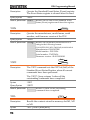
:ABORt ................................................................................... 62
:ABORt
Set
Description
The :ABORt command will cancel any triggered
actions.
Syntax
:ABORt
Apply Commands
:APPLy .................................................................................... 62
Set
:APPLy
Query
Description
The apply command sets the voltage and current
at the same time.
Syntax
:APPLy
{<NRf>(V)|MINimum|MAXimum[,<NRf>(A)|MINimu
m|MAXimum]}
Query Syntax
:APPLy?
Parameter/
<NRf>(V)
Return parameter MINimum
MAXimum
<NRf>(A)
MINimum
MAXimum
Example
Voltage setting.
Minimum voltage level
Maximum voltage level
Current setting.
Minimum voltage level
Maximum voltage level
APPL MIN, MIN
Sets the current and voltage to the minimum settings.
62
REMOTE CONTROL
Display Commands
:DISPlay:MENU[:NAME] ................................................... 63
:DISPlay[:WINDow]:TEXT:CLEar .................................... 63
:DISPlay[:WINDow]:TEXT[:DATA]................................. 64
:DISPlay:BLINk ..................................................................... 64
Set
:DISPlay:MENU[:NAME]
Query
Description
The DISPlay MENU command selects a screen
menu or queries the current screen menu.
Syntax
:DISPlay:MENU[:NAME] <NR1>
Query Sytax
:DISPlay:MENU[:NAME]?
Parameter/
<NR1> Description
Measure voltage & current
Return parameter 0
Not Used
1~2
Set Menu
3
OVP / OCP Menu
4
Not Used.
5~99
100~199 F-00~99 Menu.
200~229 F100~F129 Menu.
Example
DISP:MENU:NAME 0
Sets the display to the Voltage/Current display screen.
:DISPlay[:WINDow]:TEXT:CLEar
Set
Description
Clears the text on the main screen from
the :DISPlay[:WINDow]:TEXT[:DATA] command.
Syntax
:DISPlay[:WINDow]:TEXT:CLEar
63
PSU Programming Manual
Set
:DISPlay[:WINDow]:TEXT[:DATA]
Query
Description
Sets or queries the data text that will be written to
the display. Writing to the display will overwrite
data that is currently on the screen. Overwriting a
display area with a shorter string may or may not
overwrite the screen. The string must be enclosed
in quotes: “STRING”. Only ASCII characters 20H
to 7EH can be used in the <string>.
Syntax
:DISPlay[:WINDow]:TEXT[:DATA] <string>
Query Syntax
:DISPlay[:WINDow]:TEXT[:DATA]?
Parameter/
<string> ASCII character 20H to 7EH can be used to in
the string parameter. The string must be
Return parameter
enclosed in quotes: “STRING”
Example
DISP:WIND:TEXT:DATA “STRING”
Writes STRING to the display.
Query Example
DISP:WIND:TEXT:DATA?
“STRING”
Returns the text data string on the screen.
Set
:DISPlay:BLINk
Query
Description
Turns blink on or off for the display. Blink is set to
OFF by default.
Syntax
:DISPlay:BLINk {<bool>|OFF|ON}
Query Syntax
Parameter
:DISPlay:BLINk?
OFF | 0 Turns blink OFF
ON | 1 Turns blink ON
Return parameter <bool> Returns the blink status.
Example
DISP:BLIN 1
Turns blink ON.
64
REMOTE CONTROL
Initiate Commands
:INITiate:CONTinuous[:TRANsient] ................................ 65
:INITiate[:IMMediate]:NAME ............................................ 65
:INITiate[:IMMediate][:TRANsient] ................................... 66
Set
:INITiate:CONTinuous[:TRANsient]
Query
Description
This command continuously initiates software
triggers for the transient or output triggers.
Syntax
:INITiate:CONTinuous[:TRANsient] {<bool>|OFF|ON}
Query Syntax
Parameter
:INITiate:CONTinuous[:TRANsient]?
OFF | 0 OFF
ON | 1 ON
OFF
Return parameter 0
ON
1
Example
INIT:TRAN 1
Turns on the continuous trigger.
:INITiate[:IMMediate]:NAME
Set
Description
The INITiate command starts the TRANsient or
OUTPut trigger.
Syntax
Parameter
:INITiate[:IMMediate]:NAME {TRANsient|OUTPut}
TRANSient Starts the TRANsient trigger.
Starts the OUTPut trigger.
OUTPut
Example
INITiate:NAME TRANient
Starts the TRANSient trigger.
65
PSU Programming Manual
:INITiate[:IMMediate][:TRANsient]
Set
Description
This command controls the enabling of output
triggers. When a trigger is enabled, a trigger causes
the specified action to occur. If the trigger system
is not enabled, all triggers are ignored.
Syntax
:INITiate[:IMMediate][:TRANsient]
Example
INIT
66
REMOTE CONTROL
Measure Commands
:MEASure[:SCALar]:ALL[:DC] ........................................... 67
:MEASure[:SCALar]:CURRent[:DC] .................................. 67
:MEASure[:SCALar]:VOLTage[:DC] ................................. 67
:MEASure[:SCALar]:POWer[:DC] ...................................... 68
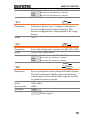
:MEASure[:SCALar]:ALL[:DC]
Description
Query
Takes a measurement and returns the average
output current and voltage
Syntax
:MEASure[:SCALar]:ALL[:DC]?
<voltage>,<current>
Return parameter "+0.0000,+0.0000"
Returns the voltage (V) and
current (A), respectively.
:MEASure[:SCALar]:CURRent[:DC]
Description
Query
Takes a measurement and returns the average
output current
Syntax
:MEASure[:SCALar]:CURRent[:DC]?
Returns the current in amps.
Return parameter "+0.0000"
:MEASure[:SCALar]:VOLTage[:DC]
Query
Description
Takes a measurement and returns the average
output voltage.
Syntax
Return
:MEASure[:SCALar]:VOLTage[:DC]?
Returns the voltage in volts.
"+0.0000"
67
PSU Programming Manual
:MEASure[:SCALar]:POWer[:DC]
Query
Description
Takes a measurement and returns the average
output power.
Syntax
Return
:MEASure[:SCALar]:POWer[:DC]?
Returns the power measured in watts.
"+0.0000"
68
REMOTE CONTROL
Memory Commands
:MEMory:TRIGgered ........................................................... 69
Set
:MEMory:TRIGgered
Query
Description
Sets or queries which memory is loaded when a
trigger input is received and the trigger input is
configured to load a memory setting.
Related
Commands
:SYSTem:CONFigure:TRIGger:INPut:SOURce
Syntax
:MEMory:TRIGgered {<NR1>|MINimum|MAXimum}
:SYSTem:CONFigure:TRIGger:OUTPut:SOURce
Return Syntax
Parameter
:MEMory:TRIGgered? [MINimum|MAXimum]
0(M1)~2(M3)
<NR1>
MINimum
MAXimum
Returns the memory setting
Return Parameter <NR1>
69
PSU Programming Manual
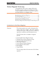
Output Commands
:OUTPut:DELay:ON ........................................................... 70
:OUTPut:DELay:OFF .......................................................... 70
:OUTPut:MODE .................................................................. 71
:OUTPut[:STATe][:IMMediate] .......................................... 71
:OUTPut[:STATe]:TRIGgered ............................................ 71
:OUTPut:PROTection:CLEar ............................................. 72
:OUTPut:PROTection:TRIPped ......................................... 72
Set
:OUTPut:DELay:ON
Query
Description
Sets the Delay Time in seconds for turning the
output on. The delay is set to 0.00 by default.
Syntax
:OUTPut:DELay:ON {<NR2>|MINimum|MAXimum}
Query Syntax
Parameter
:OUTPut:DELay:ON?
<NR2> 0.00~99.99 seconds, where 0=no delay.
Return parameter "0.00"
Returns the delay on time in seconds until the
output is turned on.
Set
:OUTPut:DELay:OFF
Query
Description
Sets the Delay Time in seconds for turning the
output off. The delay is set to 0.00 by default.
Syntax
:OUTPut:DELay:OFF {<NR2> |MINimum|MAXimum}
Return Syntax
Parameter
:OUTPut:DELay:OFF?
<NR2> 0.00~99.99 seconds, where 0=no delay.
Return parameter "0.00"
70
Returns the delay off time in seconds until the
output is turned off.
REMOTE CONTROL
Set
:OUTPut:MODE
Query
Description
Sets the PSU output mode. This is the equivalent to
the F-03 (V-I Mode Slew Rate Select) settings.
Syntax
:OUTPut:MODE {<NR1>|CVHS|CCHS|CVLS|CCLS}
Return Syntax
Parameter
:OUTPut:MODE?
CVHS | 0 CV high speed priority
CCHS | 1 CC high speed priority
CVLS | 2 CV slew rate priority
CCLS | 3 CC slew rate priority
Return parameter <NR1>
Returns the output mode.
Set
:OUTPut[:STATe][:IMMediate]
Query
Description
Turns the output on or off.
Syntax
:OUTPut[:STATe][:IMMediate] { <bool> | OFF | ON }
Query Syntax
Parameter
:OUTPut[:STATe][:IMMediate]?
OFF | 0 Turns the output off.
ON | 1 Turns the output on.
Return parameter <bool>
Returns output status of the instrument.
Set
:OUTPut[:STATe]:TRIGgered
Query
Description
Turns the output on or off when a software trigger
is generated.
Syntax
:OUTPut[:STATe]:TRIGgered { <bool>|OFF|ON }
Query Syntax
Parameter
:OUTPut[:STATe]:TRIGgered?
OFF | 0 Turns the output off when a software trigger
ON | 1
Return parameter <bool>
is generated (*TRG).
Turns the output on when a software trigger
is generated (*TRG).
Returns output trigger status of the
instrument.
71
PSU Programming Manual
:OUTPut:PROTection:CLEar
Set
Description
Clears over-voltage, over-current and overtemperature (OVP, OCP, OTP) protection circuits.
It also clears the shutdown and sense protection
circuit. The AC failure protection cannot be
cleared.
Syntax
:OUTPut:PROTection:CLEar
:OUTPut:PROTection:TRIPped
Query
Description
Queries the unit to see if a protection circuit has
been tripped.
Syntax
Return
:OUTPut:PROTection:TRIPped?
0 = No protection error
<boolean>
72
1 = A protection error had occured
REMOTE CONTROL
Sense Commands
:SENSe:AVERage:COUNt .................................................. 73
Set
:SENSe:AVERage:COUNt
Query
Description
Sets or queries the level of smoothing for the
average setting.
Syntax
:SENSe:AVERage:COUNt
{<NR1>|LOW|MIDDle|HIGH}
Return Syntax
:SENSe:AVERage:COUNt?
Low setting
Parameter
LOW | 0
MIDDle | 1 Middle setting
High setting
HIGH | 2
Returns the average setting.
Return Parameter <NR1>
73
PSU Programming Manual
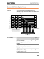
Status Commands
For an overview of all the status registers, their associated register
contents and the system diagram, please see the status overview on
page 112
:STATus:OPERation[:EVENt] ........................................... 74
:STATus:OPERation:CONDition ...................................... 74
:STATus:OPERation:ENABle ............................................ 75
:STATus:OPERation:PTRansition ...................................... 75
:STATus:OPERation:NTRansition ..................................... 75
:STATus:QUEStionable[:EVENt] ...................................... 75
:STATus:QUEStionable:CONDition ................................. 76
:STATus:QUEStionable:ENABle ....................................... 76
:STATus:QUEStionable:PTRansition ................................ 76
:STATus:QUEStionable:NTRansition................................ 76
:STATus:PRESet ................................................................... 77
:STATus:OPERation[:EVENt]
Description
Query
Queries the Operation Status Event register and
clears the contents of the register.
Syntax
Return
:STATus:OPERation[:EVENt]?
<NR1> Returns the bit sum of the Operation Status
Event register.
:STATus:OPERation:CONDition
Query
Description
Queries the Operation Status register. This query
will not clear the register.
Syntax
Return
:STATus:OPERation:CONDition?
<NR1> Returns the bit sum of the Operation
74
Condition register.
REMOTE CONTROL
Set
:STATus:OPERation:ENABle
Query
Description
Sets or queries the bit sum of the Operation Status
Enable register.
Syntax
:STATus:OPERation:ENABle <NR1>
Query Syntax
:STATus:OPERation:ENABle?
Parameter
<NR1> 0~32767
Return parameter <NR1> 0~32767
Set
:STATus:OPERation:PTRansition
Query
Description
Sets or queries the bit sum of the positive
transition filter of the Operation Status register.
Syntax
:STATus:OPERation:PTRansition <NR1>
:STATus:OPERation:PTRansition?
Parameter
<NR1> 0~32767
Return parameter <NR1> 0~32767
Set
:STATus:OPERation:NTRansition
Query
Description
Sets or queries the bit sum of the negative
transition filter of the Operation Status register.
Syntax
:STATus:OPERation:NTRansition <NR1>
Query Syntax
:STATus:OPERation:NTRansition?
Parameter
<NR1> 0~32767
Return parameter <NR1> 0~32767
:STATus:QUEStionable[:EVENt]
Description
Query
Queries the bit sum of the Questionable Status
Event register. This query will also clear the
contents of the register.
Query Syntax
:STATus:QUEStionable[:EVENt]?
Return parameter <NR1> 0~32767
75
PSU Programming Manual
:STATus:QUEStionable:CONDition
Description
Query
Queries the status (bit sum) of the Questionable
Status register. This query will not clear the
register.
Query Syntax
:STATus:QUEStionable:CONDition?
Return parameter <NR1> 0~32767
Set
:STATus:QUEStionable:ENABle
Query
Description
Sets or queries the bit sum of the Questionable
Status Enable register.
Syntax
:STATus:QUEStionable:ENABle <NR1>
Query Syntax
:STATus:QUEStionable:ENABle?
Parameter
<NR1> 0~32767
Return parameter <NR1> 0~32767
Set
:STATus:QUEStionable:PTRansition
Query
Description
Sets or queries the bit sum of the positive
transition filter of the Questionable Status register.
Syntax
:STATus:QUEStionable:PTRansition <NR1>
Return Syntax
:STATus:QUEStionable:PTRansition?
Parameter
<NR1> 0~32767
Return parameter <NR1> 0~32767
Set
:STATus:QUEStionable:NTRansition
Query
Description
Sets or queries the negative transition filter of the
Questionable Status register.
Syntax
:STATus:QUEStionable:NTRansition <NR1>
Query Syntax
:STATus:QUEStionable:NTRansition?
76
REMOTE CONTROL
Parameter
<NR1>
Return parameter <NR1>
0~32767
0~32767
:STATus:PRESet
Description
Set
This command resets the ENABle register, the
PTRansistion filter and NTRansistion filter on the
Operation Status and Questionable Status
Registers. The registers/filters will be reset to a
default value.
Default Register/Filter Values
Setting
QUEStionable Status Enable
0x0000
QUEStionable Status Positive Transition 0x7FFF
QUEStionable Status Negative Transition 0x0000
Operation Status Enable
0x0000
Operation Status Positive Transition
0x7FFF
Operation Status Negative Transition
0x0000
Summary: The Questionable Status Enable
registers and the Operation Status Enable registers
are both reset to 0.
The Questionable Status and Operation Status
Positive Transition filters are all set high (0x7FFF)
and the Negative Transition filters are all set low
(0x0000). I.e., only positive transitions will be
recognized for the Questionable Status and
Operation Status registers.
Syntax
:STATus:PRESet
77
PSU Programming Manual
Source Commands
[:SOURce]:CURRent:EXTernal:RANGe........................... 78
[:SOURce]:CURRent[:LEVel][:IMMediate]
[:AMPLitude].......................................................................... 79
[:SOURce]:CURRent[:LEVel]:TRIGgered[:AMPLitude]. 79
[:SOURce]:CURRent:LIMit:AUTO .................................... 80
[:SOURce]:CURRent:PROTection:DELay ........................ 80
[:SOURce]:CURRent:PROTection[:LEVel] ...................... 80
[:SOURce]:CURRent:PROTection:STATe ........................ 81
[:SOURce]:CURRent:PROTection:TRIPped .................... 81
[:SOURce]:CURRent:SLEWrate:RISing............................. 82
[:SOURce]:CURRent:SLEWrate:FALLing ........................ 82
[:SOURce]:MODE? .............................................................. 83
[:SOURce]:RESistance[:LEVel][:IMMediate]
[:AMPLitude].......................................................................... 83
[:SOURce]:VOLTage:EXTernal:RANGe .......................... 84
[:SOURce]:VOLTage[:LEVel][:IMMediate]
[:AMPLitude].......................................................................... 84
[:SOURce]:VOLTage[:LEVel]:TRIGgered[:AMPLitude] 84
[:SOURce]:VOLTage:LIMit:AUTO ................................... 85
[:SOURce]:VOLTage:LIMit:LOW ...................................... 85
[:SOURce]:VOLTage:PROTection[:LEVel] ...................... 86
[:SOURce]:VOLTage:PROTection:TRIPped .................... 86
[:SOURce]:VOLTage:SLEWrate:RISing ............................ 87
[:SOURce]:VOLTage:SLEWrate:FALLing ........................ 87
Set
[:SOURce]:CURRent:EXTernal:RANGe
Query
Description
Sets or queries the CC or CV control range that is
used during external control. Note: the setting will
only be valid after the power has been cycled.
Syntax
[:SOURce]:CURRent:EXTernal:RANGe {LOW|HIGH}
Query Syntax
[:SOURce]:CURRent:EXTernal:RANGe?
A range of 0 V to 5 V is used.
Parameter/Return LOW
A range of 0 V to 10 V is used.
parameter
HIGH
78
REMOTE CONTROL
Example
CURR:EXT:RANG?
LOW
Returns LOW range.
[:SOURce]:CURRent[:LEVel][:IMMediate]
[:AMPLitude]
Set
Query
Description
Sets or queries the current level in amps. For
externally set current levels (from the analog
control connector) the set current level is returned.
Syntax
[:SOURce]:CURRent[:LEVel][:IMMediate][:AMPLitude]
{<NR2>(A)|MINimum|MAXimum}
Query Syntax
[:SOURce]:CURRent[:LEVel][:IMMediate][:AMPLitude]?
Parameter/Return <NR2> 0~105% of the rated current output level.
Minimum current level.
parameter
MIN
Maximum current level.
MAX
Example
SOUR:CURR:LEV:IMM:AMPL?
38.000
Returns the current level in amps.
[:SOURce]:CURRent[:LEVel]:TRIGgered
[:AMPLitude]
Set
Query
Description
Sets or queries the current level in amps when a
software trigger has been generated.
Syntax
[:SOURce]:CURRent[:LEVel]:TRIGgered[:AMPLitude]
{<NR2> (A)| MINimum|MAXimum}
Query Syntax
Parameter
[:SOURce]:CURRent[:LEVel]:TRIGgered[:AMPLitude]?
<NR2> 0%~105% of the rated current output in amps.
Minimum current level.
MIN
Maximum current level.
MAX
Return Parameter <NR2> Returns the current level.
79
PSU Programming Manual
Example
SOUR:CURR:LEV:TRIG:AMPL?
38.000
Returns the maximum possible current level in amps.
Set
[:SOURce]:CURRent:LIMit:AUTO
Query
Description
Enables or disables the limit on the current setting.
Syntax
[:SOURce]:CURRent:LIMit:AUTO {<bool>|OFF|ON}
Query Syntax
Parameter
[:SOURce]:CURRent:LIMit:AUTO?
OFF | 0 Disable the setting current limit
ON | 1 Enable the setting current limit
Return parameter <bool> Returns the setting in <bool> format.
Example
SOUR:CURR:LIM:AUTO 0
Disables the current limit.
Set
[:SOURce]:CURRent:PROTection:DELay
Query
Description
Sets the Delay Time for OCP in seconds for turning
the output off. The delay is set to 0.1 by default.
Syntax
[:SOURce]:CURRent:PROTection:DELay
{<NR2>|MINimum|MAXimum}
Query Syntax
Parameter
[:SOURce]:CURRent:PROTection:DELay?
<NR2> 0.1~2.0 seconds, where 0=no delay
The maximum allowed delay time
MAX
The minimum allowed delay time
MIN
Return parameter <NR2> Returns the delay time in seconds
Example
SOUR:CURR:PROT:DEL MAX
Sets the current protection delay to the maximum.
Set
[:SOURce]:CURRent:PROTection[:LEVel]
Description
80
Query
Sets or queries the OCP (over-current protection)
level in amps.
REMOTE CONTROL
Syntax
[:SOURce]:CURRent:PROTection[:LEVel] {<NR2>(A)
|MINimum|MAXimum}
Query Syntax
Parameter
[:SOURce]:CURRent:PROTection[:LEVel]?
<NR2> Current protection level.
Minimum: Depend on the unit type:
if Irated * 0.1 > 5A, then minimum = 5A,
MIN
MAX
Return parameter <NR2>
Example
else minimum = Irated * 0.1
Maximum: Irated * 1.1
Minimum current level.
Maximum current level.
Returns the current protection level.
SOUR:CURR:PROT:LEV?
+5.000
Returns the minimum possible current level in amps.
Set
[:SOURce]:CURRent:PROTection:STATe
Query
Description
Turns OCP (over-current protection) on or off.
Syntax
[:SOURce]:CURRent:PROTection:STATe
{<bool>|OFF|ON}
Query Syntax
Parameter
[:SOURce]:CURRent:PROTection:STATe?
OFF | 0 Turns the OCP off.
ON | 1 Turns the OCP on.
Return parameter <bool>
Example
Returns the over current protection state in
<bool> format.
SOUR:CURR:PROT:STAT OFF
Turns OCP off.
Set
[:SOURce]:CURRent:PROTection:TRIPped
Query
Description
Returns the state of the current protection circuits.
Query Syntax
[:SOURce]:CURRent:PROTection:TRIPped?
Return parameter <bool>
Returns protection status.
81
PSU Programming Manual
Example
SOUR:CURR:PROT:TRIP?
>0
The protection circuit has not been tripped.
Set
[:SOURce]:CURRent:SLEWrate:RISing
Query
Description
Sets or queries the rising current slew rate. This is
only applicable for CC slew rate priority mode.
Syntax
[:SOURce]:CURRent:SLEWrate:RISing
{<NR2>(A)|MINimum|MAXimum}
Query Syntax
Parameter
[:SOURce]:CURRent:SLEWrate:RISing?
<NR2> Per step is between 0.001A/msec and rated
MIN
MAX
Return parameter <NR2>
Example
current divided by 100 msec.
Minimum rising current slew rate is
0.001A/msec.
Maximum rising current slew rate is rated
current divided by 100msec.
Returns the step current in amps.
SOUR:CURR:SLEW:RIS?
0.950
Sets the rising current slew rate to 0.950 A/ms.
Set
[:SOURce]:CURRent:SLEWrate:FALLing
Query
Description
Sets or queries the falling current slew rate. This is
only applicable for CC slew rate priority mode.
Syntax
[:SOURce]:CURRent:SLEWrate:FALLing
{<NR2>(A)|MINimum|MAXimum}
Query Syntax
Parameter
[:SOURce]:CURRent:SLEWrate:FALLing?
<NR2> Per step is between 0.001A/msec and rated
MIN
MAX
Return Parameter <NR2>
82
current divided by 100 msec.
Minimum falling current slew rate is
0.001A/msec.
Maximum falling current slew rate is rated
current divided by 100msec.
Returns the step current
REMOTE CONTROL
Example
SOUR:CURR:SLEW:FALL MAX
Sets the falling current slew rate to the maximum.
Set
[:SOURce]:MODE?
Description
Query
Returns the status of the output mode (CC, CV,
Off) of the power supply.
The interface will return “CV’ if the supply is in
Constant Voltage Mode, “CC” if the supply is in
Constant Current Mode or “OFF” if the supply
output is off.
Query Syntax
[:SOURce]:MODE?
Return parameter <string> Returns the output state as a string, “CC”,
“CV”, “OFF”
Example
:SOUR:MODE?
>CC
The power supply is currently in CC mode.
[:SOURce]:RESistance[:LEVel][:IMMediate]
[:AMPLitude]
Set
Query
Description
Sets or queries the internal resistance in ohms.
Syntax
[:SOURce]:RESistance[:LEVel][:IMMediate][:AMPLitude
] {<NR2>(OHM)|MINimum|MAXimum}
Query Syntax
[:SOURce]:RESistance[:LEVel][:IMMediate][:AMPLitude
]?
<NR2> Resistance in ohms:
Parameter
MIN
MAX
Return parameter <NR2>
Example
0 ohm ~ Rrated = Vrated/Irated
Minimum internal resistance in ohms
Maximum internal resistance in ohms
Returns the internal resistance in ohms.
SOUR:RES:LEV:IMM:AMPL 0.1
Sets the internal resistance to 100mΩ.
83
PSU Programming Manual
Set
[:SOURce]:VOLTage:EXTernal:RANGe
Query
Description
Sets or queries the CC or CV control range that is
used during external control. Note: the setting will
only be valid after the power has been cycled.
Syntax
[:SOURce]:VOLTage:EXTernal:RANGe {LOW|HIGH}
Query Syntax
[:SOURce]:VOLTage:EXTernal:RANGe?
A range of 0 V to 5 V is used.
Parameter/Return LOW
A range of 0 V to 10 V is used.
parameter
HIGH
Example
VOLT:EXT:RANG?
LOW
Returns LOW range.
[:SOURce]:VOLTage[:LEVel][:IMMediate]
[:AMPLitude]
Set
Query
Description
Sets or queries the voltage level in volts.
Syntax
[:SOURce]:VOLTage[:LEVel][:IMMediate][:AMPLitude]
{<NR2>(V)|MINimum|MAXimum}
Query Syntax
Parameter
[:SOURce]:VOLTage[:LEVel][:IMMediate][:AMPLitude]?
<NRf> 0~105% of the rated output voltage in volts.
Minimum voltage level
MIN
Maximum voltage level
MAX
Return parameter <NR2> Returns the voltage level in volts
Example
SOUR:VOLT:LEV:IMM:AMPL 10
Sets the voltage level to 10 volts.
[:SOURce]:VOLTage[:LEVel]:TRIGgered
[:AMPLitude]
Description
84
Set
Query
Sets or queries the voltage level in volts when a
software trigger has been generated.
REMOTE CONTROL
Syntax
[:SOURce]:VOLTage[:LEVel]:TRIGgered[:AMPLitude]
{<NR2>(V)|MINimum|MAXimum}
Query Syntax
Parameter
[:SOURce]:VOLTage[:LEVel]:TRIGgered[:AMPLitude]?
<NR2> 0%~105% of the rated voltage output in volts.
Minimum current level.
MIN
Maximum current level.
MAX
Return parameter <NR2> Returns the voltage level.
Example
SOUR:VOLT:LEV:TRIG:AMPL 10
Sets the voltage level to 10 volts when a software
trigger is generated.
Set
[:SOURce]:VOLTage:LIMit:AUTO
Description
Query
Sets whether to limit the voltage setting so that it
does not exceed the OVP setting or become lower
than the UVL setting.
If you enable the limit when the OVP setting is
lower than the voltage setting, the OVP setting will
be set to 105 % of the voltage setting.
If you enable the limit when the UVL setting is
higher than the voltage setting, the UVL setting
will be set equal to the voltage setting.
Syntax
[:SOURce]:VOLTage:LIMit:AUTO {<bool>|OFF|ON}
Query Syntax
Parameter
[:SOURce]:VOLTage:LIMit:AUTO?
OFF | 0 Disable the limit setting
ON | 1 Enable the limit setting
Return parameter <bool> Returns the setting in <bool> format.
Example
SOUR:VOLT:LIM:AUTO 0
Disables the limit setting.
Set
[:SOURce]:VOLTage:LIMit:LOW
Query
Description
Sets or queries the under voltage (UVL) trip point.
Syntax
[:SOURce]:VOLTage:LIMit:LOW
<NR2>(V)|MINimum|MAXimum
85
PSU Programming Manual
Query Syntax
[:SOURce]:VOLTage:LIMit:LOW?
Parameter/Return <NR2> 0 ~ the present setting voltage
MIN
MAX
Example
Minimum allowed voltage level
Maximum allowed voltage level
SOUR:VOLT:LIM:LOW MAX
Sets the UV> level to its maximum.
Set
[:SOURce]:VOLTage:PROTection[:LEVel]
Query
Description
Sets or queries the overvoltage protection level.
Syntax
[:SOURce]:VOLTage:PROTection[:LEVel]
{<NR2>(V)|MINimum|MAXimum}
Query Syntax
[:SOURce]:VOLTage:PROTection[:LEVel]?
Parameter/Return <NR2> Minimum: Depends on the unit type:
MIN
MAX
Example
if Vrated * 0.1 > 5V, then Minimum = 5V,
else Minimum = Vrated * 0.1
Maximum: Vrated * 1.1
Minimum OVP level
Maximum OVP level
SOUR:VOLT:PROT:LEV MAX
Sets the OVP level to its maximum.
Set
[:SOURce]:VOLTage:PROTection:TRIPped
Description
Query
Sets or queries the overvoltage protection level.
Query Syntax
[:SOURce]:VOLTage:PROTection:TRIPped?
Return parameter <bool>
Protection not tripped
0
Protection tripped
1
Example
SOUR:VOLT:PROT:TRIP?
>0
Indicates that the OVP protection has not been
tripped.
86
REMOTE CONTROL
Set
[:SOURce]:VOLTage:SLEWrate:RISing
Query
Description
Sets or queries the rising voltage slew rate. This is
only applicable for CV slew rate priority mode.
Syntax
Query Syntax
[:SOURce]:VOLTage:SLEWrate:RISing
{<NR2>(V)|MINimum|MAXimum}
Parameter
[:SOURce]:VOLTage:SLEWrate:RISing?
<NR2> Per step is between 0.001V/msec and rated
MIN
MAX
Return parameter <NR2>
Example
voltage divided by 100msec.
Minimum rising voltage slew rate is
0.001V/msec.
Maximum rising voltage slew rate is rated
voltage divided by 100msec.
Returns the slew rate in V/msec.
SOUR:VOLT:SLEW:RIS MAX
Sets the rising voltage slew rate to its maximum.
Set
[:SOURce]:VOLTage:SLEWrate:FALLing
Query
Description
Sets or queries the falling voltage slew rate. This is
only applicable for CV slew rate priority mode.
Syntax
[:SOURce]:VOLTage:SLEWrate:FALLing
{<NR2>(V)|MINimum|MAXimum}
Query Syntax
Parameter
[:SOURce]:VOLTage:SLEWrate:FALLing?
<NR2> Per step is between 0.001V/msec and rated
MIN
MAX
Return parameter <NR2>
Example
voltage divided by 100msec.
Minimum falling voltage slew rate is
0.001V/msec.
Maximum falling voltage slew rate is rated
voltage divided by 100msec.
Returns the voltage slew rate in V/msec
SOUR:VOLT:SLEW:FALL MIN
Sets the falling voltage slew rate to its minimum.
87
PSU Programming Manual
System Function Command
:SYSTem:BEEPer[:IMMediate] ........................................... 89
:SYSTem:CONFigure:BEEPer[:STATe]............................ 90
:SYSTem:CONFigure:BLEeder[:STATe] .......................... 90
:SYSTem:CONFigure:CURRent:CONTrol ....................... 90
:SYSTem:CONFigure:VOLTage:CONTrol ...................... 91
:SYSTem:CONFigure:OUTPut:PON[:STATe] ................ 92
:SYSTem:CONFigure:PROTection:RECovery ................. 92
:SYSTem:CONFigure:MSLave ............................................ 93
:SYSTem:CONFigure:OUTPut:EXTernal:MODE .......... 93
:SYSTem:CONFigure:OUTPut:EXTernal[:STATe] ........ 94
:SYSTem:CONFigure:MONitor:RANGe .......................... 94
:SYSTem:CONFigure:TRIGger:INPut:SOURce .............. 94
:SYSTem:CONFigure:TRIGger:INPut:WIDTh ............... 95
:SYSTem:CONFigure:TRIGger:OUTPut:SOURce ......... 95
:SYSTem:CONFigure:TRIGger:OUTPut:WIDTh........... 96
:SYSTem:CONFigure:TRIGger:OUTPut:LEVel ............. 96
:SYSTem:COMMunicate:ENABle ...................................... 97
:SYSTem:COMMunicate:GPIB[:SELF]:ADDRess .......... 97
:SYSTem:COMMunicate:LAN:IPADdress ....................... 98
:SYSTem:COMMunicate:LAN:GATEway ........................ 98
:SYSTem:COMMunicate:LAN:SMASk .............................. 99
:SYSTem:COMMunicate:LAN:MAC ................................. 99
:SYSTem:COMMunicate:LAN:DHCP............................... 99
:SYSTem:COMMunicate:LAN:DNS ................................ 100
:SYSTem:COMMunicate:RLSTate .................................... 100
:SYSTem:COMMunicate:TCPip:CONTrol ..................... 100
:SYSTem:COMMunicate:SERial:LANGuage[:SELect].. 101
:SYSTem:COMMunicate:SERial[:RECeive] :TRANsmit
:BAUD .................................................................................. 101
:SYSTem:COMMunicate:SERial[:RECeive] :TRANsmit
:BITS ..................................................................................... 102
:SYSTem:COMMunicate:SERial[:RECeive]:TRANsmit
:PARity .................................................................................. 102
:SYSTem:COMMunicate:SERial[:RECeive]:TRANsmit
:SBITs .................................................................................... 103
:SYSTem:COMMunicate:USB:FRONt:STATe............... 103
:SYSTem:COMMunicate:USB:REAR:MODE................ 103
:SYSTem:COMMunicate:USB:REAR:STATe ................. 104
:SYSTem:ERRor .................................................................. 104
:SYSTem:KLOCk ................................................................ 104
88
REMOTE CONTROL
:SYSTem:KEYLock:MODE.............................................. 105
:SYSTem:ERRor:ENABle .................................................. 105
:SYSTem:LANGuage:EMULation.................................... 105
:SYSTem:LANGuage:[:SELect] ......................................... 105
:SYSTem:PRESet ................................................................. 106
:SYSTem:VERSion .............................................................. 106
:SYSTem:REBoot ................................................................ 106
Set
:SYSTem:BEEPer[:IMMediate]
Query
Description
This command causes an audible tone to be
generated by the instrument. The duration time is
specified in seconds.
Syntax
:SYSTem:BEEPer[:IMMediate]
{<NR1>|MINimum|MAXimum}
Query Syntax
Parameter
:SYSTem:BEEPer[:IMMediate]? [MINimum|MAXimum]
0 ~ 3600 seconds.
<NR1>
MINimum Sets the beeper time to the minimum (0
MAXimum
Return parameter <NR1>
Example 1
seconds)
Sets the beeper time to the maximum
(3600 seconds)
Returns the remaining beeper duration
time in seconds or returns the maximum
or minimum beeper time in seconds (for
the [MINimum|MAXimum] query
parameters).
:SYST:BEEP 10
**after a 2 second wait**
:SYST:BEEP?
>8
The first command turns the beeper on for 10
seconds. After 2 seconds the SYST:BEEP? query
returns the remaining beeper time (8 seconds).
Example 2
:SYST:BEEP? MAX
>3600
Returns the maximum settable beeper time in
seconds.
89
PSU Programming Manual
Set
:SYSTem:CONFigure:BEEPer[:STATe]
Query
Description
Sets or queries the buzzer state on/off.
Syntax
:SYSTem:CONFigure:BEEPer[:STATe]
{<bool>|OFF|ON}
Query Syntax
Parameter
:SYSTem:CONFigure:BEEPer[:STATe]?
Turns the buzzer off.
OFF | 0
Turns the buzzer on.
ON | 1
Return parameter <bool>
Returns the buzzer status.
Set
:SYSTem:CONFigure:BLEeder[:STATe]
Query
Description
Sets or queries the status of the bleeder resistor.
Syntax
:SYSTem:CONFigure:BLEeder[:STATe]
{<NR1>|OFF|ON|AUTO}
Query Syntax
Parameter
:SYSTem:CONFigure:BLEeder[:STATe]?
Turns the bleeder resistor off.
OFF | 0
Turns the bleeder resistor on.
ON | 1
AUTO | 2 Turn the AUTO mode on.
Return parameter <NR1>
Returns bleeder resistor status.
Set
:SYSTem:CONFigure:CURRent:CONTrol
Query
Description
Sets or queries the CC control mode (local control
(panel), external voltage control, external
resistance control). This setting is applied only
after the unit is reset.
Syntax
:SYSTem:CONFigure:CURRent:CONTrol
{ <NR1>|NONE|VOLTage|RRISing|RFALling|
VISolation }
Query Syntax
:SYSTem:CONFigure:CURRent:CONTrol?
90
REMOTE CONTROL
Parameter
<NR1>
0 | NONE
1 | VOLTage
2 | RRISing
3 | RFALling
4 | VISolation
Description
Local (Panel) control
External voltage control
External resistance control; 10kΩ or
5kΩ = Io max*, 0kΩ = Io min.
External resistance control; 10kΩ or
5kΩ = Io min*, 0kΩ = Io max.
External voltage control (isolated)
*The resistance value depends on the
[:SOURce]:CURRent:EXTernal:RANGe command.
If the range is high, then the resistance is 10kΩ, else it is
5kΩ. See page 78 for details.
Returns the current control
Return Parameter <NR1>
configuration.
Set
:SYSTem:CONFigure:VOLTage:CONTrol
Query
Description
Sets or queries the CV control mode (local control
(panel), external voltage control, external
resistance control). This setting is applied only
after the unit is reset.
Syntax
:SYSTem:CONFigure:VOLTage:CONTrol
{ <NR1>|NONE|VOLTage|RRISing|RFALling|
VISolation }
Query Syntax
Parameter
:SYSTem:CONFigure:VOLTage:CONTrol?
Description
<NR1>
Local (Panel) control
0 | NONE
External voltage control
1 | VOLTage
External resistance control; 10kΩ or
2 | RRISing
3 | RFALling
4 | VISolation
5kΩ = Io max*, 0kΩ = Io min.
External resistance control; 10kΩ or
5kΩ = Io min*, 0kΩ = Io max.
External voltage control (isolated)
*The resistance value depends on the
[:SOURce]:VOLTage:EXTernal:RANGe command.
If the range is high, then the resistance is 10kΩ, else it is
5kΩ. See page 78 for details.
91
PSU Programming Manual
Returns the current control
configuration.
Return Parameter <NR1>
Set
:SYSTem:CONFigure:OUTPut:PON[:STATe]
Query
Description
Sets the output state at power-on. This is the
equivalent to the F-92 (Output Status when Power
ON) power on configuration settings. These
settings only apply after the unit has been reset.
Syntax
Return Syntax
:SYSTem:CONFigure:OUTPut:PON[:STATe]
{<NR1>|{SAFE|OFF}|{FORCe|ON}|AUTO}
Parameter
:SYSTem:CONFigure:OUTPut:PON[:STATe]?
The PSU turns on in the same state
SAFE | OFF | 0
FORCe | ON | 1
AUTO | 2
Return parameter 0
1
2
the unit was in prior to the previous
shut down. The output is set to off
(default).
The PSU turns on in the same state
the unit was in prior to the previous
shut down. The output is set to on.
The PSU turns on in the same state
the unit was in prior to the previous
shut down, but with the same output
on/off setting.
The power on output setting is
“SAFE” or “OFF”.
The power on output setting is
“FORCe” or “ON”.
The power on output setting is
“AUTO”.
Set
:SYSTem:CONFigure:PROTection:RECovery
Query
Description
Sets or queries how the OHP, FAN, AC-FAIL, and
SD alarms are cleared.
Syntax
Return Syntax
:SYSTem:CONFigure:PROTection:RECovery
{SAFE|AUTO}
Parameter
:SYSTem:CONFigure:PROTection:RECovery?
The output is not turned on automatically
SAFE
92
when the cause of the alarm is fixed.
REMOTE CONTROL
AUTO
The output is turned on automatically
when the cause of the alarm is fixed.
Set
:SYSTem:CONFigure:MSLave
Query
Description
Sets or queries the unit operation mode. This
setting is only applied after the unit has been reset.
Syntax
:SYSTem:CONFigure:MSLave { <NR1> }
Query Syntax
:SYSTem:CONFigure:MSLave?
Parameter/Return <NR1> Description
Master/Local
0
Master/with 1 unit in Parallel (total:2 units)
1
Master/with 2 units in Parallel (total: 3 units)
2
Master/with 3 units in Parallel (total: 4 units)
3
Slave
4
:SYSTem:CONFigure:OUTPut:EXTernal
:MODE
Description
Set
Query
Sets the logic used to turn the output on or off
when using an external contact. This is the
equivalent to the F-94 (External Output Logic)
power on configuration settings.
This setting is only applied after the unit has been
reset.
Syntax
Return Syntax
:SYSTem:CONFigure:OUTPut:EXTernal:MODE
{<NR1>|LOW|HIGH}
:SYSTem:CONFigure:OUTPut:EXTernal:MODE?
Parameter
HIGH | 0 Active high
LOW | 1 Active low
Return Parameter <NR1> Returns the logic setting.
93
PSU Programming Manual
:SYSTem:CONFigure:OUTPut:EXTernal
[:STATe]
Set
Query
Description
Sets whether the output will be turned on or off
externally. By default this setting is turned off. This
setting is only applied after the unit has been reset.
Syntax
:SYSTem:CONFigure:OUTPut:EXTernal[:STATe]
{<bool>|OFF|ON}
Return Syntax
Parameter
:SYSTem:CONFigure:OUTPut:EXTernal[:STATe]?
ON | 1 External control is performed.
OFF | 0 External control is not performed.
Return parameter <bool>
Returns output status of the instrument.
Set
:SYSTem:CONFigure:MONitor:RANGe
Description
Query
This command is used to select the monitor
voltage range.
This setting is only applied after the unit has been
reset.
Syntax
:SYSTem:CONFigure:MONitor:RANGe
{<NR1>|LOW|HIGH}
Return Syntax
Parameter
:SYSTem:CONFigure:MONitor:RANGe?
HIGH | 0 10V
LOW | 1 5V
Return Parameter <NR1> Returns the logic setting.
:SYSTem:CONFigure:TRIGger:INPut
:SOURce
Set
Query
Description
Sets or queries what action will be performed on
receiving a trigger.
Syntax
:SYSTem:CONFigure:TRIGger:INPut:SOURce
{<NR1>|NONE|OUTPut|SETTing|MEMory}
Return Syntax
:SYSTem:CONFigure:TRIGger:INPut:SOURce?
94
REMOTE CONTROL
Parameter
No input trigger.
NONE | 0
OUTPut | 1 Toggles the output on receiving a trigger.
SETTing | 2 Sets the voltage/current on receiving a
trigger.
MEMory | 3 Loads a memory setting on receiving a
Return Parameter <NR1>
trigger.
Returns the input source.
:SYSTem:CONFigure:TRIGger:INPut
:WIDTh
Set
Query
Description
Sets or queries the input trigger pulse width. A
setting of 0 indicates that the input trigger is
controlled by the trigger input level, rather than a
trigger pulse.
Syntax
:SYSTem:CONFigure:TRIGger:INPut:WIDTh
{<NR2>|MINimum|MAXimum}
Return Syntax
:SYSTem:CONFigure:TRIGger:INPut:WIDTh?
[MINimum|MAXimum]
0 ~ 60ms.
Parameter
<NR2>
MINimum Minimum width = 0.
MAXimum 60ms
Returns the trigger input width.
Return Parameter <NR2>
:SYSTem:CONFigure:TRIGger:OUTPut
:SOURce
Set
Query
Description
Sets or queries the output trigger source.
Syntax
:SYSTem:CONFigure:TRIGger:OUTPut:SOURce
{<NR1>|NONE|OUTPut|SETTing|MEMory}
Return Syntax
Parameter
:SYSTem:CONFigure:TRIGger:OUTPut:SOURce?
No output trigger.
NONE | 0
OUTPut | 1 Output trigger is generated by a change in
the output.
SETTing | 2 Output trigger is generated when a setting
is changed.
MEMory | 3 Output trigger is generated when a
memory setting is loaded.
95
PSU Programming Manual
Return Parameter <NR1>
Returns the output source.
:SYSTem:CONFigure:TRIGger:OUTPut
:WIDTh
Set
Query
Description
Sets or queries the output trigger pulse width. A
setting of 0 indicates that the output trigger will go
high or low, depending on the output level setting.
Related
Commands
:SYSTem:CONFigure:TRIGger:OUTPut:LEVel
Syntax
:SYSTem:CONFigure:TRIGger:OUTPut:WIDTh
{<NR2>|MINimum|MAXimum}
Return Syntax
:SYSTem:CONFigure:TRIGger:OUTPut:WIDTh?
[MINimum|MAXimum]
0 ~ 60ms.
Parameter
<NR2>
MINimum Minimum width = 0
MAXimum 60ms
Returns the trigger output width.
Return Parameter <NR2>
:SYSTem:CONFigure:TRIGger:OUTPut
:LEVel
Set
Query
Description
Sets the polarity of the output trigger level when
the output trigger pulse width is set to 0.
Syntax
:SYSTem:CONFigure:TRIGger:OUTPut:LEVel
{<NR1>|LOW|HIGH}
Return Syntax
Parameter
:SYSTem:CONFigure:TRIGger:OUTPut:LEVel?
Sets the output trigger to active low.
0 | LOW
Sets the output trigger to active high.
1 | HIGH
Returns the trigger output width.
Return Parameter <NR1>
96
REMOTE CONTROL
Set
:SYSTem:COMMunicate:ENABle
Description
Query
Enables/Disables GPIB, USB or other remote
interfaces such as Sockets and the Web Server.
This setting is only applied after the unit has been
reset.
Syntax
:SYSTem:COMMunicate:ENABle {<bool>
|OFF|ON,GPIB|USB|LAN|SOCKets|WEB|SERial}
Query Syntax
:SYSTem:COMMunicate:ENABle?
{GPIB|USB|LAN|SOCKets|WEB|SERial}
Disables the selected interface.
OFF | 0
Enables the selected interface.
ON | 1
Parameter 1
Parameter 2
GPIB
USB
LAN
SOCKets
WEB
SERial
Return Parameter <bool>
Example
Select GPIB
Select USB
Select LAN
Select Sockets
Select the web server
Selected Serial (UART)
Returns the status of the selected mode.
SYST:COMM:ENAB 1,USB
Turns the USB interface on.
Query Example
SYST:COMM:ENAB? USB
1
Queries the USB state, returns 1 (USB is on).
:SYSTem:COMMunicate:GPIB[:SELF]
:ADDRess
Set
Query
Description
Sets or queries the GPIB address. Note: the setting
will only be valid after the power has been cycled.
Syntax
:SYSTem:COMMunicate:GPIB[:SELF]:ADDRess
<NR1>
Query Syntax
:SYSTem:COMMunicate:GPIB[:SELF]:ADDRess?
97
PSU Programming Manual
Parameter/Return <NR1>
Example
0~30
SYST:COMM:GPIB:SELF:ADDR 15
Sets the GPIB address to 15.
Set
:SYSTem:COMMunicate:LAN:IPADdress
Query
Description
Sets or queries LAN IP address. Note: the setting
will only be valid after the power has been cycled.
Syntax
:SYSTem:COMMunicate:LAN:IPADdress <string>
Query Syntax
:SYSTem:COMMunicate:LAN:IPADdress?
Parameter/Return <string> LAN IP address in string format ( “address”)
Applicable ASCII characters: 20H to 7EH
Example
SYST:COMM:LAN:IPAD “172.16.5.111”
Sets the IP address to 172.16.5.111.
Set
:SYSTem:COMMunicate:LAN:GATEway
Query
Description
Sets or queries the Gateway address. Note: the
setting will only be valid after the power has been
cycled.
Syntax
:SYSTem:COMMunicate:LAN:GATEway <string>
Query Syntax
:SYSTem:COMMunicate:LAN:GATEway?
Parameter/Return <string> Gateway address in string format ( “address”)
Applicable ASCII characters: 20H to 7EH
Example
98
SYST:COMM:LAN:GATE “172.16.0.254”
Sets the LAN gateway to 172.16.0.254.
REMOTE CONTROL
Set
:SYSTem:COMMunicate:LAN:SMASk
Query
Description
Sets or queries the LAN subnet mask. Note: the
setting will only be valid after the power has been
cycled.
Syntax
:SYSTem:COMMunicate:LAN:SMASk <string>
Query Syntax
:SYSTem:COMMunicate:LAN:SMASk?
Parameter/Return <string> Subnet mask in string format ( “mask”)
Applicable ASCII characters: 20H to 7EH
Example
SYST:COMM:LAN:SMASk “255.255.0.0”
Sets the LAN mask to 255.255.0.0.
:SYSTem:COMMunicate:LAN:MAC
Description
Query
Returns the unit MAC address as a string. The
MAC address cannot be changed.
Query Syntax
:SYSTem:COMMunicate:LAN:MAC?
Return parameter <string> Returns the MAC address in the following
format “FF-FF-FF-FF-FF-FF”
Example
SYST:COMM:LAN:MAC?
02-80-AD-20-31-B1
Returns the MAC address.
Set
:SYSTem:COMMunicate:LAN:DHCP
Query
Description
Turns DHCP on/off. Queries the DHCP status.
Note: the setting will only be valid after the power
has been cycled.
Syntax
:SYSTem:COMMunicate:LAN:DHCP
{<bool>|OFF|ON}
Query Syntax
Parameter
:SYSTem:COMMunicate:LAN:DHCP?
OFF | 0 DHCP off
ON | 1 DHCP on
Return parameter <bool> Returns the DHCP status.
99
PSU Programming Manual
Set
:SYSTem:COMMunicate:LAN:DNS
Query
Description
Sets or queries the DNS address. Note: the setting
will only be valid after the power has been cycled.
Syntax
:SYSTem:COMMunicate:LAN:DNS <string>
Query Syntax
:SYSTem:COMMunicate:LAN:DNS?
Parameter/Return <string> DNS in string format ( “mask”)
Applicable ASCII characters: 20H to 7EH
Example
SYST:COMM:LAN:DNS “172.16.1.252”
Sets the DNS to 172.16.1.252.
Set
:SYSTem:COMMunicate:RLSTate
Query
Description
Enables or disables local/remote state of the
instrument.
Syntax
:SYSTem:COMMunicate:RLSTate
{LOCal|REMote|RWLock}
Query Syntax
:SYSTem:COMMunicate:RLSTate?
All keys are valid. This instrument is
Parameter/Return LOCal
controlled by the front panel controls.
parameter
REMote All keys are invalid, except for the [local] key
and the ability to turn the output off.
RWLock All keys are invalid. The instrument can only
be controlled remotely.
Example
:SYST:COMM:RLST LOCAL
Sets the operating mode to local.
:SYSTem:COMMunicate:TCPip:CONTrol
Description
Query
Queries the socket port number.
Query Syntax
:SYSTem:COMMunicate:TCPip:CONTrol?
Return parameter <NR1> 0000 ~ 9999
Example
SYST:COMM:TCP:CONT?
>2268
Returns the socket port number.
100
REMOTE CONTROL
:SYSTem:COMMunicate:SERial:LANGuage[
:SELect]
Set
Query
Description
Sets or queries the communication protocol for the
serial port.
Syntax
:SYSTem:COMMunicate:SERial:LANGuage[:SELect]
{"SCPI"|"LEGACY"}
Query Syntax
:SYSTem:COMMunicate:SERial:LANGuage[:SELect]?
Sets the communication protocol to SCPI.
Parameter/Return "SCPI"
parameter
"LEGACY" Sets the communication protocol to legacy
mode. (Emulate TDK Genesys)
Example
SYST:COMM:SER:LANG?
>SCPI
Indicates that the communication protocol is set to SCPI.
:SYSTem:COMMunicate:SERial[:RECeive]
:TRANsmit:BAUD
Set
Query
Description
Sets or queries the UART baud rate. Note: the
setting will only be valid after the power has been
cycled.
Syntax
:SYSTem:COMMunicate:SERial[:RECeive]:TRANsmit
:BAUD <NR1>
Query Syntax
:SYSTem:COMMunicate:SERial[:RECeive]:TRANsmit
:BAUD?
Parameter/Return <NR1> 2400, 4800, 9600, 19200, 38400, 57600,
115200
Example
SYST:COMM:SER:TRAN:BAUD?
>2400
Returns the baud rate settings.
101
PSU Programming Manual
:SYSTem:COMMunicate:SERial[:RECeive]
:TRANsmit:BITS
Set
Query
Description
Sets or queries the UART number of data bits.
Note: the setting will only be valid after the power
has been cycled.
Syntax
:SYSTem:COMMunicate:SERial[:RECeive]:TRANsmit
:BITS <NR1>
Query Syntax
:SYSTem:COMMunicate:SERial[:RECeive]:TRANsmit
:BITS?
Parameter/Return <NR1>
7 bits
parameter
0
8 bits
1
Example
SYST:COMM:SER:TRAN:BITS?
>1
Indicates that 8 data bits are used for the UART
connection.
:SYSTem:COMMunicate:SERial[:RECeive]:T
RANsmit:PARity
Set
Query
Description
Sets or queries the parity of the UART connection.
Note: the setting will only be valid after the power
has been cycled.
Syntax
:SYSTem:COMMunicate:SERial[:RECeive]:TRANsmit
:PARity <NR1>
Query Syntax
:SYSTem:COMMunicate:SERial[:RECeive]:TRANsmit
:PARity?
None
Parameter/Return 0
parameter
Odd
1
Even
2
Example
SYST:COMM:SER:TRAN:PARity?
>1
Indicates that odd parity is used for the UART
connection.
102
REMOTE CONTROL
:SYSTem:COMMunicate:SERial[:RECeive]:T
RANsmit:SBITs
Set
Query
Description
Sets or queries the number of stop bits used for the
UART connection. Note: the setting will only be
valid after the power has been cycled.
Syntax
:SYSTem:COMMunicate:SERial[:RECeive]:TRANsmit
:SBITs<NR1>
Query Syntax
:SYSTem:COMMunicate:SERial[:RECeive]:TRANsmit
:SBITs?
1 stop bit
Parameter/Return 0
2 stop bits
parameter
1
Example
SYST:COMM:SER:TRAN:SBITs?
>1
Indicates that one stop bit is used for the UART
connection.
:SYSTem:COMMunicate:USB:FRONt:STATe
Description
Query
Queries the front panel USB-A port state.
Query Syntax
:SYSTem:COMMunicate:USB:FRONt:STATe?
<NR1>Absent
Return parameter 0
<NR1>Mass Storage
1
Set
:SYSTem:COMMunicate:USB:REAR:MODE
Query
Description
Sets or queries the speed of the rear panel USB B
port. This setting is applied only after the unit is
reset.
Syntax
:SYSTem:COMMunicate:USB:REAR:MODE
{<NR1>|DISable|AUTO|FULL}
Query Syntax
:SYSTem:COMMunicate:USB:REAR:MODE?
103
PSU Programming Manual
Parameter
0 | DISable
1 | AUTO
2 | FULL
Return parameter <NR1>
0
1
2
Disable
Auto detect speed
Full speed
Disable
Auto detect speed
Full speed
:SYSTem:COMMunicate:USB:REAR:STATe
Description
Query
Queries the rear panel USB-B port state.
Query Syntax
:SYSTem:COMMunicate:USB:REAR:STATe?
<NR1>Absent
Return parameter 0
<NR1>Connected to the PC
1
:SYSTem:ERRor
Description
Queries the error queue. The last error message is
returned. A maximum of 32 errors are stored in the
error queue.
Query Syntax
:SYSTem:ERRor?
Return parameter <string>
Example
Query
Returns an error code followed by
an error message as a single string.
SYSTem:ERRor?
-100, “Command error”
Set
:SYSTem:KLOCk
Query
Description
Enables or disables the front panel key lock.
Syntax
:SYSTem:KLOCk {<bool>|OFF|ON }
Query Syntax
Parameter
:SYSTem:KLOCk?
OFF | 0 Panel keys unlocked
ON | 1 Panel keys locked
Return parameter <bool> Returns the key lock status.
104
REMOTE CONTROL
Set
:SYSTem:KEYLock:MODE
Query
Description
Sets or queries the keylock mode. This setting is
the equivalent to the F-19 function setting.
Syntax
:SYSTem:KEYLock {<bool>|OFF|ON}
Query Syntax
:SYSTem:KEYLock?
Parameter/Return 0 | OFF Panel lock: allow output off.
parameter
1 | ON Panel lock: allow output on/off.
:SYSTem:ERRor:ENABle
Set
Query
Description
Clears the Error Queue and enables all error
messages to be placed in the System Error Queue.
Syntax
:SYSTem:ERRor:ENABle
Set
:SYSTem:LANGuage:EMULation
Query
Description
Sets or queries the command language.
Syntax
:SYSTem:LANGuage:EMULation
{“NONE”|”N5700”|”GENSYS”|”PWX”}
Query Syntax
:SYSTem:LANGuage:EMULation?
Emulation is not used. This is the default
Parameter/
“NONE”
setting
Return parameter
“N5700”
N5700/N8700 emulation is used.
“GENSYS” GENESYS emulation is used.
“PWX”
PAG emulation is used.
Set
:SYSTem:LANGuage:[:SELect]
Query
Description
Sets or queries the command language.
Syntax
:SYSTem:LANGuage[:SELect] {“SCPI”|”LEGACY”}
Query Syntax
:SYSTem:LANGuage[:SELect]?
105
PSU Programming Manual
Parameter/
“SCPI”
Return parameter
“LEGACY”
Use the SCPI command language. This the
default language
Use the GEN command language.
:SYSTem:PRESet
Description
Loads the default settings.
Syntax
:SYSTem:PRESet
:SYSTem:VERSion
Set
Query
Description
Returns the version of the PSU SCPI version.
Query Syntax
:SYSTem:VERSion?
Return
<string> Returns the SCPI version as a string.
Query Example
SYST:VERS?
>1999.9
:SYSTem:REBoot
Description
Reboots the PSU system.
Syntax
:SYSTem:REBoot
106
Set
REMOTE CONTROL
Trigger Commands
:TRIGger:OUTPut:SOURce .............................................. 107
:TRIGger:OUTPut[:IMMediate] ....................................... 107
:TRIGger[:TRANsient]:SOURce....................................... 107
:TRIGger[:TRANsient][:IMMediate] ................................ 108
Set
:TRIGger:OUTPut:SOURce
Query
Description
Sets or queries the trigger source of the output
trigger.
Syntax
:TRIGger:OUTPut:SOURce {BUS|IMMediate|EXTernal}
Query Syntax
:TRIGger:OUTPut:SOURce?
Output trigger is generated by the bus.
Parameter/
BUS
Return parameter IMMediate Output trigger is immediately generated.
The output trigger is generated when an
EXTernal
external signal triggers it.
Example
:TRIGger:OUTPut:SOURce?
EXT
Sets the output trigger source to EXT.
:TRIGger:OUTPut[:IMMediate]
Set
Description
Generates an immediate trigger for the output
trigger system.
Syntax
:TRIGger:OUTPut[:IMMediate]
Example
:TRIG:OUTP
Example
:TRIG:MEM
Set
:TRIGger[:TRANsient]:SOURce
Description
Query
Sets or queries the source of the transient trigger.
107
PSU Programming Manual
Syntax
:TRIGger[:TRANsient]:SOURce
{BUS|IMMediate|EXTernal}
Query Syntax
:TRIGger[:TRANsient]:SOURce?
Transient trigger is generated by the bus.
Parameter/
BUS
Return parameter IMMediate Transient trigger is immediately
EXTernal
Example
generated.
The transient trigger is generated when an
external signal triggers it.
:TRIG:SOUR?
EXT
Sets the transient trigger source to EXT.
:TRIGger[:TRANsient][:IMMediate]
Set
Description
Generates an immediate trigger for the transient
trigger system.
Syntax
:TRIGger[:TRANsient][:IMMediate]
Example
:TRIG
108
REMOTE CONTROL
IEEE 488.2 Common Commands
*CLS ...................................................................................... 109
*ESE ...................................................................................... 109
*ESR ...................................................................................... 109
*IDN ..................................................................................... 110
*OPC ..................................................................................... 110
*RCL...................................................................................... 110
*RST ...................................................................................... 111
*SAV...................................................................................... 111
*SRE ...................................................................................... 111
*STB ...................................................................................... 112
*TRG ..................................................................................... 112
*TST ...................................................................................... 112
*WAI ..................................................................................... 112
*CLS
Set
Description
The *CLS command clears all the event registers,
including the status byte, event status and error
queue.
Syntax
*CLS
Set
*ESE
Query
Description
Sets or queries the Standard Event Status Enable
register.
Syntax
*ESE <NR1>
Query Syntax
*ESE?
Parameter
<NR1>
Return parameter <NR1>
*ESR
0~255
Returns the bit sum of the Standard Event
Status Enable register.
Query
109
PSU Programming Manual
Description
Queries the Standard Event Status (Event) register.
The Event Status register is cleared after it is read.
Query Syntax
*ESR?
Return parameter <NR1>
Returns the bit sum of the Standard Event
Status (Event) register and clears the register.
*IDN
Description
Query
Queries the manufacturer, model name, serial
number, and firmware version of the PSU.
Query Syntax
*IDN?
Return parameter <string> Returns the instrument identification as a
string in the following format:
GW-INSTEK,PSU-2076,TW123456,01.00.20110101
Manufacturer: GW-INSTEK
Model number : PSU-3036
Serial number : TW123456
Firmware version : 01.00.20110101
Set
*OPC
Description
Query
The *OPC command sets the OPC bit (bit0) of the
Standard Event Status Register when all current
commands have been processed.
The *OPC? Query returns 1 when all the
outstanding commands have completed.
Syntax
*OPC
Query Syntax
*OPC?
Return parameter 1
Returns 1 when all the outstanding
commands have completed.
*RCL
Set
Description
Recalls the contents stored in memory slot M1, M2
or M3.
Syntax
*RCL {<NR1>|MAX|MIN}
110
REMOTE CONTROL
Parameter
<NR1>
MIN
MAX
0, 1, 2 (as memory M1 , M2, M3)
Recalls the M1 memory contents.
Recalls the M3 memory contents.
*RST
Set
Description
Performs a device reset. Configures the unit to a
known configuration (default settings). This
known configuration is independent of the usage
history.
Syntax
*RST
*SAV
Description
Set
Saves the settings into memory slot M1, M2 or M3.
Syntax
*SAV {<NR1>|MIN|MAX}
Return parameter <NR1> 0, 1, 2 (as memory M1 , M2, M3)
Saves the M1 memory contents.
MIN
Saves the M3 memory contents.
MAX
Set
*SRE
Query
Description
Sets or queries the Service Request Enable register.
The Service Request Enable register determines
which registers of the Status Byte register are able
to generate service requests.
Syntax
*SRE <NR1>
Query Syntax
*SRE?
Parameter
<NR1>
Return parameter <NR1>
0~255
Returns the bit sum of the Service Request
Enable register.
111
PSU Programming Manual
*STB
Description
Query
Queries the bit sum of the Status Byte register with
MSS (Master summary Status) replacing the RQS
bit (bit 6).
Query Syntax
*STB?
Return parameter <NR1>
Returns the bit sum of the Status Byte register
with the MSS bit (bit 6).
*TRG
Set
Description
The *TRG command is able to generate a “get”
(Group Execute Trigger). If the PSU cannot accept
a trigger at the time of the command, an error
message is generated (-211, “Trigger ignored”).
Syntax
*TRG
*TST
Description
Query
Executes a self test.
Query Syntax
*TST?
Return parameter 0
<NR1>
*WAI
Returns “0” if there are no errors.
Returns an error code <NR1> if there is an
error.
Set
Description
Prevents any other commands or queries from
being executed until all outstanding commands
have completed.
Syntax
*WAI
112
REMOTE CONTROL
Status Register Overview
To program the PSU power supply effectively,
the Status registers need to be understood. This
chapter explains in detail how the Status registers
are used and how to configure them.
Introduction to the Status Registers .................................. 113
The Status Registers ............................................................ 114
Questionable Status Register Group ................................. 115
Operation Status Register Group ...................................... 117
Standard Event Status Register Group ............................. 120
Status Byte Register & Service Request Enable Register122
Introduction to the Status Registers
The status registers are used to determine the
status of the power supply. The status registers
maintain the status of the protection conditions,
operation conditions and instrument errors.
Overview
The PSU Series have a number of register
groups:
Questionable Status Register Group
Standard Event Status Register Group
Operation Status Register Group
Status Byte Register
Service Request Enable Register
Service Request Generation
Error Queue
Output Buffer
The next page shows the structure of the Status
registers.
113
PSU Programming Manual
The Status Registers
Questionable Status Register
Event
Enable
OV (Over-Voltage)
Condition PTR/NTP
0
0
0
0
OC (Over-Current)
1
1
1
1
Not Used
2
2
2
2
POW (AC Power Off)
3
3
3
3
OT (Over-Temperature)
4
4
4
4
Not Used
5
5
5
5
Not Used
6
6
6
6
Not Used
7
7
7
7
VL (Voltage-Limit)
8
8
8
8
CL (Current-Limit)
9
9
9
9
Not Used
10
10
10
10
SD (Shutdown Alarm)
11
11
11
11
Power-Limit
12
12
12
12
Not Used
13
13
13
13
Not Used
14
14
14
14
Not Used
15
15
15
15
Output
Buffer
:
:
:
Error Que
:
:
:
Standard Event Status
Register
Event
Enable
OPC (Operation Complete)
0
0
RQC (Request Control)
1
1
QUE (Query Error)
2
2
DDE (Device Dependent Error)
3
3
EXE (Execution Error)
4
4
CME (Command Error)
5
5
URQ (User Request)
6
6
PON (Power On)
7
7
0
0
1
1
ERR
2
2
QUES
3
3
MAV
4
ESB
5
OPER
4
5
6
7
Service
Request
Generation
Event
Enable
CAL (Calibration mode)
0
0
0
0
Not Used
1
1
1
1
Not Used
2
2
2
2
Not Used
3
3
3
3
Not Used
4
4
4
4
WTG (Waiting for Trigger)
5
5
5
5
Not Used
6
6
6
6
Not Used
7
7
7
7
CV (Constant Voltage Mode)
8
8
8
Not Used
9
9
9
9
CC (Constant Current Mode)
10
10
10
10
OND (Output ON Delay)
11
11
11
11
OFD (Output OFF Delay)
8
12
12
12
12
Not Used
13
13
13
13
PR (Program Running)
14
14
14
14
Not Used
15
15
15
15
114
Service
Request
Enable
Register
RQS 6
Operation Status Register
Condition PTR/NTP
Status
Byte
Register
MSS
6
7
REMOTE CONTROL
Questionable Status Register Group
The Questionable Status Register Group
indicates if any protection modes or limits have
been tripped.
Overview
Questionable Status Register
Condition
PTR/NTP
Event
OV
0
0
0
OC
1
1
1
Not Used
2
2
2
POW
3
3
3
OT
4
4
4
Not Used
5
5
5
Not Used
6
6
6
Not Used
7
7
7
VL
8
8
8
CL
9
9
9
Not Used
10
10
10
SD
11
11
11
PL
12
12
12
Not Used
13
13
13
Not Used
14
14
14
Not Used
15
15
15
Enable
&
0
&
1
&
2
&
3
&
4
&
5
&
6
&
7
&
8
&
9
&
10
&
11
&
12
&
13
&
14
&
STATus:QUEStionable:CONDition? STATus:QUEStionable:EVENt?
15
STATus:QUEStionable:ENABle <NRf>
STATus:QUEStionable:ENABle?
STATus:QUEStionable:NTRansition <NRf>
STATus:QUEStionable:NTRansition?
STATus:QUEStionable:PTRansition <NRf>
STATus:QUEStionable:PTRansition?
Logical OR
To Status Byte Register
Bit Summary
Event
Bit #
Bit
Weight
OV (Over-Voltage)
0
1
1
2
3
8
Over voltage protection has been
tripped
OC (Over-Current)
Over current protection has been
tripped
POW (AC Power Off)
AC power switch is off
115
PSU Programming Manual
OT (Over Temperature)
4
16
8
256
9
512
SD (Shutdown Alarm)
11
2048
PL (Power-Limit)
12
4096
Over temperature protection has
been tripped
VL (Voltage Limit)
Voltage limit has been reached
CL (Current Limit)
Current limit has been reached
Condition
Register
The Questionable Status Condition Register
indicates the status of the power supply. If a bit
is set in the Condition register, it indicates that
the event is true. Reading the condition register
does not change the state of the condition
register.
PTR/NTR Filters
The PTR/NTR (Positive/Negative transition)
register determines the type of transition
conditions that will set the corresponding bit in
the Event Registers. Use the Positive transition
filter to view events that change from false to
positive, and use the negative transition filter to
view events that change from positive to
negative.
Positive Transition
0→1
Negative Transition
1→0
Event Register
The PTR/NTR Register will dictate the type of
transition conditions will set the corresponding
bits in the Event Register. If the Event Register
is read, it will be cleared to 0.
Enable Register
The Enable register determines which Events in
the Event Register will be used to set the QUES
bit in the Status Byte Register.
116
REMOTE CONTROL
Operation Status Register Group
The Operation Status Register Group indicates
the operating status of the power supply.
Overview
Operation Status Register
Condition
PTR/NTP
Event
CAL
0
0
0
Not Used
1
1
1
Not Used
2
2
2
Not Used
3
3
3
Not Used
4
4
4
WTG
5
5
5
Not Used
6
6
6
Not Used
7
7
7
CV
8
8
8
Not Used
9
9
9
CC
10
10
10
OND
11
11
11
OFD
12
12
12
Not Used
13
13
13
PR
14
14
14
Not Used
15
15
15
STATus:OPERation:CONDition?
Enable
&
0
&
1
&
2
&
3
&
4
&
5
&
6
&
7
&
8
&
9
&
10
&
11
&
12
&
13
&
14
&
STATus:OPERation:EVENt?
15
STATus:OPERation:ENABle <NRf>
STATus:OPERation:ENABle?
STATus:OPERation:NTRansition <NRf>
STATus:OPERation:NTRansition?
STATus:OPERation:PTRansition <NRf>
STATus:OPERation:PTRansition?
Logical OR
To Status Byte Register
Bit Summary
Event
Bit #
Bit
Weight
CAL (Calibration mode)
0
1
5
32
Indicates if the PSU is in
calibration mode.
WTG (Waiting for trigger)
Indicates if the PSU is waiting for
a trigger.
117
PSU Programming Manual
CV (Constant voltage mode)
8
256
10
1024
11
2048
12
4096
14
16384
Indicates if the PSU is in CV
mode.
CC (Constant current mode)
Indicates if the PSU is in CC
mode.
OND (Output ON Delay)
Indicates if Output ON delay time
is active
OFD (Output OFF Delay)
Indicates if Output OFF delay
time is active
PR (Program Running)
Indicates if a Test is running
Condition
Register
The Operation Status Condition Register
indicates the operating status of the power
supply. If a bit is set in the Condition register, it
indicates that the event is true. Reading the
condition register does not change the state of
the condition register.
PTR/NTR Filters
The PTR/NTR (Positive/Negative transition)
register determines the type of transition
conditions that will set the corresponding bit in
the Event Registers. Use the Positive transition
filter to view events that change from false to
positive, and use the negative transition filter to
view events that change from positive to
negative.
118
Positive Transition
0→1
Negative Transition
1→0
REMOTE CONTROL
Event Register
The PTR/NTR Register will dictate the type of
transition conditions will set the corresponding
bits in the Event Register. If the Event Register
is read, it will be cleared to 0.
Enable Register
The Enable register determines which
registered Events in the Event Register will be
used to set the OPER bit in the Status Byte
Register.
119
PSU Programming Manual
Standard Event Status Register Group
Overview
The Standard Event Status Register Group
indicates if any errors have occurred. The bits
of the Event register are set by the error event
queue.
Standard Event Status Register
Event
OPC
0
RQC
1
QUE
2
DDE
3
EXE
4
CME
5
URQ
6
PON
7
Enable
&
0
&
1
&
2
&
3
&
4
&
5
&
6
&
*ESR?
7
*ESE <NRf>
*ESE?
Logical OR
To Status Byte Register
Bit Summary
Event
Bit #
Bit
Weight
OPC (Operation complete)
0
1
RQC (Request control)
1
2
QUE (Query Error)
2
4
3
8
The OCP bit is set when all
selected pending operations are
complete. This bit is set in
response to the *OPC command.
The Query Error bit is set in
response to an error reading the
Output Queue. This can be
caused by trying to read the
Output Queue when there is no
data present.
DDE (Device Dependent Error)
Device specific error.
120
REMOTE CONTROL
EXE (Execution Error)
4
16
5
32
URQ (User Request)
6
64
PON (Power On)
7
128
The EXE bit indicates an
execution error due to one of the
following: illegal command
parameter, parameter out of
range, invalid parameter, the
command didn’t execute due to
an overriding operation
condition.
CME (Command Error)
The CME bit is set when a syntax
error has occurred. The CME bit
can also be set when a <GET>
command is received within a
program message.
Indicates the power is turned on.
Event Register
Any bits set in the event register indicate that
an error has occurred. Reading the Event
register will reset the register to 0.
Enable Register
The Enable register determines which Events in
the Event Register will be used to set the ESB
bit in the Status Byte Register.
121
PSU Programming Manual
Status Byte Register & Service Request Enable Register
Overview
The Status Byte register consolidates the status
events of all the status registers. The Status Byte
register can be read with the *STB? query and
can be cleared with the *CLS command.
Output
Buffer
:
:
:
Error Que
:
:
:
Service
Request
Enable
Register
Status
Byte
Register
From
Questionable
Status Register
From Standard
Event Status
Register
From Operation
Status Register
0
&
1
ERR
2
QUES
3
MAV
4
ESB
5
MSS
6
OPER
7
0
&
1
&
2
&
3
&
4
&
5
6
&
*STB?
7
*SRE <NRf>
*SRE?
Logical OR
Bit Summary
Event
Bit #
Bit
Weight
ERR (Error Event/Queue)
2
4
3
8
If data is present in the Error
queue, the ERR bit will be set.
QUES (Questionable Status
Register)
The summary bit for the
Questionable Status Register
group.
MAV (Message Available) This is 4
set when there is data in the
Output Queue waiting to be read.
122
16
REMOTE CONTROL
(ESB) Event Summary Bit. The
ESB is the summary bit for the
Standard Event Status Register
group.
5
32
MSS Bit
6
64
The MSS Bit is the summary of
the Status Byte Register and
Service Request register (bits 1-5,
7). This will be set to 1.
OPER (Operation Status Register) 7
128
OPER bit is the summary bit for
the Operation Status Register
Group.
Status Byte
Register
Any bits set in the Status byte register acts as a
summary register for all the three other status
registers and indicates if there is a service
request, an error in the Error Queue or data in
the Output Queue. Reading the Status Byte
register will reset the register to 0.
Service Request
Enable Register
The Service Request Enable Register controls
which bits in the Status Byte Register are able to
generate service requests.
123
PSU Programming Manual
Error List
Command Errors ................................................................. 124
Execution Errors ................................................................. 128
Device Specific Errors ........................................................ 130
Query Errors ........................................................................ 131
Command Errors
Overview
An <error/event number> in the range [ -199 , 100 ] indicates that an IEEE 488.2 syntax error
has been detected by the instrument’s parser.
The occurrence of any error in this class shall
cause the command error bit (bit 5) in the event
status register (IEEE 488.2, section 11.5.1) to be
set. One of the following events has occurred:
An IEEE 488.2 syntax error has been detected by
the parser. That is, a controller-to-device
message was received which is in violation of
the IEEE 488.2 standard. Possible violations
include a data element which violates the device
listening formats or whose type is unacceptable
to the device.
An unrecognized header was received.
Unrecognized headers include incorrect devicespecific headers and incorrect or
unimplemented IEEE 488.2 common commands.
Events that generate command errors shall not
generate execution errors, device-specific errors,
or query errors; see the other error definitions in
this chapter.
124
REMOTE CONTROL
Error Code
Description
-100 Command
Error
This is the generic syntax error for devices that
cannot detect more specific errors. This code
indicates only that a Command Error as
defined in IEEE 488.2,11.5.1.1.4 has occurred.
-102 Syntax error
An unrecognized command or data type was
encountered; for example, a string was received
when the device does not accept strings.
-103 Invalid
separator
The parser was expecting a separator and
encountered an illegal character; for example,
the semicolon was omitted after a program
message unit,
MEAS:VOLT:DC?:MEASCURR:DC?
-104 Data type
error
The parser recognized a data element different
than one allowed; for example, numeric or
string data was expected but block data was
encountered.
-108 Parameter
not allowed
More parameters were received than expected
for the header; for example, the KLOCk
command only accepts one parameter, so
receiving SYSTem:KLOCk 1,0 is not allowed.
-109 Missing
parameter
Fewer parameters were recieved than required
for the header; for example, the KLOCk
command requires one parameter, so receiving
KLOCk is not allowed.
-111 Header
separator error
A character which is not a legal header
separator was encountered while parsing the
header; for example, no white space followed
the header, thus *SRE2 is an error.
125
PSU Programming Manual
-112 Program
mnemonic too
long
The header contains more that twelve
characters (see IEEE 488.2, 7.6.1.4.1).
-113 Undefined
header
The header is syntactically correct, but it is
undefined for this specific device; for example,
*XYZ is not defined for any device.
-114 Header
suffix out of range
The value of a numeric suffix attached to a
program mnemonic, see Syntax and Style
section 6.2.5.2, makes the header invalid.
-115 Unexpected
number of
parameters
The number of parameters received does not
correspond to the number of parameters
expected. This is typically due an inconsistency
with the number of instruments in the selected
group.
-120 Numeric
data error
This error, as well as errors -121 through -129,
are generated when parsing a data element
which apprears to be numeric, including the
nondecimal numeric types. This particular error
message should be used if the device cannot
detect a more specific error.
-121 Invalid
character in
number
An invalid character for the data type being
parsed was encountered; for example, an alpha
in a decimal numeric or a “9" in octal data.
-128 Numeric
data not allowed
A legal numeric data element was received, but
the device does not accept one in this position
for the header.
-131 Invalid suffix
The suffix does not follow the syntax described
in IEEE 488.2, 7.7.3.2, or the suffix is
inappropriate for this device.
126
REMOTE CONTROL
-141 Invalid
character data
Either the character data element contains an
invalid character or the particular element
received is not valid for the header.
-148 Character
data not allowed
A legal character data element was encountered
where prohibited by the device.
-151 Invalid string
data
A string data element was expected, but was
invalid for some reason (see IEEE 488.2, 7.7.5.2);
for example, an END message was received
before the terminal quote character.
-158 String data
not allowed
A string data element was encountered but was
not allowed by the device at this point in
parsing.
-160 Block data
error
This error, as well as errors -161 through -169,
are generated when parsing a block data
element. This particular error message should
be used if the device cannot detect a more
specific error.
-161 Invalid block
data
A block data element was expected, but was
invalid for some reason (see IEEE 488.2, 7.7.6.2);
for example, an END message was received
before the length was satisfied.
-168 Block data
not allowed
A legal block data element was encountered
but was not allowed by the device at this point
in parsing.
-178 Expression
data not allowed
A legal expression data was encountered but
was not allowed by the device at this point in
parsing.
127
PSU Programming Manual
Execution Errors
Overview
An <error/event number> in the range [ -299 , 200 ] indicates that an error has been detected
by the instrument’s execution control block.
The occurrence of any error in this class shall
cause the execution error bit (bit 4) in the event
status register (IEEE 488.2, section 11.5.1) to be
set. One of the following events has occurred:
A <PROGRAM DATA> element following a
header was evaluated by the device as outside
of its legal input range or is otherwise
inconsistent with the device’s capabilities.
A valid program message could not be properly
executed due to some device condition.
Execution errors shall be reported by the device
after rounding and expression evaluation
operations have taken place. Rounding a
numeric data element, for example, shall not be
reported as an execution error. Events that
generate execution errors shall not generate
Command Errors, device-specific errors, or
Query Errors; see the other error definitions in
this section.
Error Code
Description
-200 Execution
error
This is the generic syntax error for devices that
cannot detect more specific errors. This code
indicates only that an Execution Error as
defined in IEEE 488.2, 11.5.1.1.5 has occurred.
128
REMOTE CONTROL
-201 Invalid while
in local
Indicates that a command is not executable
while the device is in local due to a hard local
control (see IEEE 488.2, 5.6.1.5); for example, a
device with a rotary switch receives a message
which would change the switches state, but the
device is in local so the message cannot be
executed.
-203 Command
protected
Indicates that a legal password-protected
program command or query could not be
executed because the command was disabled.
-211 Trigger
ignored
Indicates that a GET, *TRG, or triggering signal
was received and recognized by the device but
was ignored because of device timing
considerations; for example, the device was not
ready to respond. Note: a DT0 device always
ignores GET and treats *TRG as a Command
Error.
-213 Init ignored
Indicates that a request for a measurement
initiation was ignored as another measurement
was already in progress.
-220 Parameter
error
Indicates that a program data element related
error occurred. This error message should be
used when the device cannot detect the more
specific errors described for errors -221 through
-229.
-221 Settings
conflict
Indicates that a legal program data element was
parsed but could not be executed due to the
current device state (see IEEE 488.2, 6.4.5.3 and
11.5.1.1.5.).
129
PSU Programming Manual
-222 Data out of
range
Indicates that a legal program data element was
parsed but could not be executed because the
interpreted value was outside the legal range as
defined by the device (see IEEE 488.2,
11.5.1.1.5.).
-224 Illegal
parameter value
Used where exact value, from a list of possibles,
was expected.
Device Specific Errors
Overview
An <error/event number> in the range [ -399 , 300 ] or [ 1 , 32767 ] indicates that the
instrument has detected an error which is not a
command error, a query error, or an execution
error; some device operations did not properly
complete, possibly due to an abnormal
hardware or firmware condition. These codes
are also used for self-test response errors. The
occurrence of any error in this class should
cause the device-specific error bit (bit 3) in the
event status register (IEEE 488.2, section 11.5.1)
to be set. The meaning of positive error codes is
device-dependent and may be enumerated or
bit mapped; the <error message>string for
positive error codes is not defined by SCPI and
available to the device designer.
Note that the string is not optional; if the
designer does not wish to implement a string
for a particular error, the null string should be
sent (for example, 42,""). The occurrence of any
error in this class should cause the devicespecific error bit (bit 3) in the event status
register (IEEE 488.2, section 11.5.1) to be set.
Events that generate device-specific errors shall
not generate command errors, execution errors,
130
REMOTE CONTROL
or query errors; see the other error definitions
in this section.
Error Code
Description
-310 System error
Indicates that some error, termed “system
error” by the device, has occurred. This code is
device-dependent.
-320 Storage fault
Indicates that the firmware detected a fault
when using data storage. This error is not an
indication of physical damage or failure of any
mass storage element.
Query Errors
Overview
An <error/event number> in the range [ -499 , 400 ] indicates that the output queue control of
the instrument has detected a problem with the
message exchange protocol described in IEEE
488.2, chapter 6. The occurrence of any error in
this class shall cause the query error bit (bit 2)
in the event status register (IEEE 488.2, section
11.5.1) to be set. These errors correspond to
message exchange protocol errors described in
IEEE 488.2, section 6.5. One of the following is
true:
An attempt is being made to read data from the
output queue when no output is either present
or pending;
Data in the output queue has been lost.
Events that generate query errors shall not
generate command errors, execution errors, or
device-specific errors; see the other error
definitions in this section.
131
PSU Programming Manual
Error Code
Description
-400 Query error
This is the generic query error for devices that
cannot detect more specific errors. This code
indicates only that a Query Error as defined in
IEEE 488.2, 11.5.1.1.7 and 6.3 has occurred.
132
PSU Programming Manual
APPENDIX
PSU Default Settings
The following default settings are the factory configuration settings
for the power supply (Function settings/Test settings).
Initial Settings
Output
LOCK
Voltage
Current
OVP
OCP
Normal Function
Settings
Output ON delay time
Output OFF delay time
V-I mode slew rate select
Internal resistance
setting
Bleeder circuit control
Buzzer ON/OFF control
OCP Delay Time
Current Setting Limit
Voltage Setting Limit
Display Memory
parameter when recalling
Auto parallel Control
Measurement Average
Setting
Alarm Recovery and
Output Status
Default Setting
Off
0 (Disabled)
0V
0A
1.1 X Vrate
1.1 X Irate
Setting
F-01
F-02
F-03
F-08
Default Setting
0.00s
0.00s
0 = CV high speed priority
0.000Ω
F-09
F-10
F-12
F-13
F-14
F-15
1 = ON
1 = ON
0.1 (seconds)
0 = OFF
0 = OFF
F-16
F-17
0 = OFF
F-18
0 = OFF
0 = Low
0 = Safe Mode
133
PSU Programming Manual
Lock Mode
Setup Rear USB Speed
GPIB address
GPIB Enable/Disable
SCPI Emulation
LAN setting
LAN
DHCP
Power On Configuration
Socket Server
Enable/Disable
Web Server
Enable/Disable
Web Password
Enable/Disable
UART Mode
UART Baudrate
UART Data Bits
UART Parity
UART Stop Bit
UART Transmission
Control Protocol
UART Address
CV Control
CC Control
Output Status when
Power ON
Master/Slave
External Out Logic
Monitor Voltage Select
Control Range
External Output Control
Function
134
F-19
F-22
F-23
F-24
F-26
0:Lock Panel, Allow Output OFF
2 = Auto detect
8
1 = Enable
0 = GW Instek
F-36
F-37
1 = Enable
1 = Enable
F-57
1 = Enable
F-59
1 = Enable
F-60
1 = Enable
F-70
F-71
F-72
F-73
F-74
1 = Enable
7 = 115200
1 = 8 bits
0 = None
0 = 1 bit
F-75
0 = SCPI
F-76
F-90
F-91
30
0= Panel control (local)
0= Panel control (local)
F-92
0 = Safe Mode
F-93
F-94
F-96
F-97
0 = Independent
0= High ON
0 = 5V
0 = 5V[5kΩ]
F-98
0 = OFF
APPENDIX
Error Messages & Messages
The following error messages or messages may appear on the PSU
screen during operation.
Error Messages
OHP
OHP1
OHP2
ALM SENS
HW OVP
AC
OVP
OCP
FAN FAIL
SHUT DOWN
Err 001
Err 002
Err 003
Err 004
Normal Messages
MSG 001
MSG 002
Communication
Interface Messages
USB ON
USB OFF
MS ON
MS OFF
Description
Master & slave board over temperature
protection in PSU
Master board over temperature protection in
PSU
Slave board over temperature protection in
PSU
Sense Alarm
Hardware over voltage protection
AC fail
Over voltage protection
Over current protection
Fan failure
Force shutdown
USB mass storage is not present
No (such)file in USB mass storage
Empty memory location
Slave PSU error status
Description
External control of output. Output off (F-94=0,
High=on)
External control of output. Output off (F-94=1,
Low=on)
Description
Rear USB port connected to PC
Rear USB port disconnected from PC
Mass storage plugged into front USB port
Mass storage removed from front USB port
135
PSU Programming Manual
LED ASCII Table Character Set
Use the following table to read the LCD display messages.
0
1
2
3
4
5
6
7
8
9
A
B
C
D
R
E
F
G
H
I
J
K
L
M
N
O
P
Q
S
T
U
V
W
X
Y
Z
(
)
+
-
,
136
INDEX
INDEX
Accessories ................................. 11
Caution symbol ............................ 4
Cleaning the instrument ............. 6
Configuration
normal function settings
operation ................................... 21
power on configuration operation23
table ................................................ 25
Default settings ........................ 133
Display diagram ........................ 16
Display format ......................... 136
Disposal instructions ................... 6
EN61010
measurement category .................. 5
pollution degree.............................. 6
Environment
safety instruction ............................ 6
Error messages ......................... 135
Ethernet
interface .......................................... 46
sockets ............................................ 49
web server...................................... 46
Front panel diagram .................. 13
Ground
Optional accessories .................. 11
Package contents ........................ 11
Power on/off
safety instruction ............................ 5
Rear panel diagram ................... 18
Remote control ........................... 30
Command list ................................ 58
Command syntax ......................... 55
Error list ....................................... 124
Ethernet configuration................. 46
Ethernet function check ............... 47
GPIB configuration....................... 33
GPIB function check ..................... 34
interface configuration ................ 31
local bus configuration ................ 42
multi-unit configuration.............. 42
mult-unit function check ............. 44
sockets configuration ................... 49
sockets function check ................. 50
Status registers ............................ 113
UART configuration .................... 38
UART function check................... 41
USB configuration ........................ 31
USB function check ...................... 32
Service operation
symbol .............................................. 4
about disassembly .......................... 5
LED conversion ........................ 136
List of features ............................ 10
Messages ................................... 135
Model differences ........................ 9
Socket server function check .... 50
UK power cord ............................. 7
Warning symbol ........................... 4
Web server function check ........ 47
137