1
13
Connector Pin Out
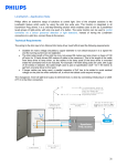
The following diagram shows the connector pin out on the sensor as it is viewed facing the sensor. The table details
pin assignments for the Sensor Connector.
Pin
1
2
3
4
5
6
7
Signal
Rx+ (Receive)
Rx- (Receive)
Tx+ (Transmit)
Tx- (Transmit)
Out Rng
Analog 1 Out (0 –10V)
Analog 1 Common
8
9
10
Analog 2 Common
Analog 2 Out (4-20mA)
Sync
11
GND
12
POWER
Front View of
Connector of Sensor
Optional Supplied Cable Pin Out
13