1
TM
e-track
User’s Manual (FW 1.00)
Digital Communications Technologies
May 11, 2009
.
Copyright
This manual is copyrighted. All type of reproduction of its content must be authorized by Digital
TM
Communications Technologies .
Document information
Version: 1.04
Type: Release.
Date of release: 11-05-09
History:
Version
1.00 04-06-08
1.01
15-08-08
1.02
20-11-08
Comments
First release
-.
Major changes for 1.00 release.
Corrected values for B signals.
Corrected info. on Diagnostic Message.
Corrected info. on Reporting Mode
Corrected examples on Event Definition.
Corrected examples on Incoming Voice call handling
Added info. for the P00 and P01 signals.
Deleted error 41 from the TAIP errors list.
Added illustration of the e-track’s box contents.
Other minor corrections.
1.03
4-12-08
Deleted errors 32,33,34,38,47,53-58,86 from the TAIP errors list.
Corrected info. on Sleep Timer’s Comm. Timeout.
Corrected info. on Battery Status.
Corrected info. on Heading Deltas.
Deleted info. about extended EV messages.
Deleted info. about over the air firmware upgrades.
Corrected various examples that used signals not supported by e-track.
Added signals F06 and F09 to the signals’ table.
The magnetic proximity sensor was renamed to the magnetic proximity switch.
Updated info. on the Quick Start Guide.
Other minor corrections.
1.04
11-05-09
Added info. for the Built-in Motion Detector.
TM
Changed info. on e-track
LEDs reference.
Changed info. on Local Lock.
Changed info. on Heading Deltas.
Changed info. on Turn unit off - Auto-turn off (Sleep Timer).
Changed info. on Reset Message.
Changed info. on Keep Alive.
Changed info. on Counters, Timers, Distancers.
Changed info. on Status.
Changed info. on F09 and F14 signals.
Changed Limited Warranty info.
Removed info. on Altitude Accuracy which will be implemented in a future release.
Firmware version
This manual applies to firmware version 1.00 of e-track
the >QVR< TAIP command.
TM
device. You can consult the unit’s firmware version with
2
Regulatory Compliance
FCC
This product operates with Wavecom’s Q24PL transmitter.
FCC Parts 22H and 24E are granted to the Wavecom Q24PL under FCC identifier O9EQ24PL001.
The antenna gain, including cable loss, must not exceed 3 dBi at 1900 MHz / 1.4 dBi at 850
MHz for mobile operating configurations and 7 dBi at 1900 MHz / 1.4 dBi at 850 MHz for fixed
mounted operations, as defined in 2.1091 and 1.1307 of the rules for satisfying RF exposure compliance.
In addition, the antenna used for this device must be installed to provide a separation distance of
at least 20 cm from all persons.
LIMITED WARRANTY
Digital Communications Technologies warrants the original purchaser that for a period of twelve(12)
months from the date of purchase, the product shall be free of defects in materials and workmanship under normal use. During the warranty period, Digital Communications Technologies shall,
at its option, repair or replace any defective product upon return of the product to its facilities, at
no charge for labor and materials. Any replacement and/or repaired parts are warranted for the
remainder of the original warranty or ninety (90) days, whichever is longer. The original owner
must promptly notify Digital Communications Technologies in writing that there is defect in material or workman-ship, such written notice to be received in all events prior to expiration of the
warranty period.
International Warranty
The warranty for international customers is the same as for any customer within the United States,
with the exception that Digital Communications Technologies shall not be responsible for any customs fees, taxes, or VAT that may be due.
Warranty Procedure
To obtain service under this warranty, please return the item(s) in question to the point of purchase. All authorized distributors and dealers have a warranty program. Anyone returning goods
to Digital Communications Technologies must first obtain an authorization number.Digital Communications Technologies will not accept any shipment whatsoever for which prior authorization
has not been obtained.
Conditions to Void Warranty
This warranty applies only to defects in parts and workmanship relating to normal use. It does
not cover:
• Damage incurred in shipping or handling
• Damage caused by disaster such as fire, flood, wind, earthquake or lightning
• Damage due to causes beyond the control of Digital Communications Technologies such as
excessive voltage, mechanical shock or water damage
• Damage caused by unauthorized attachment, alterations, modifications or foreign objects
• Damage caused by peripherals unless such peripherals were supplied by Digital Communications Technologies
• Defects caused by failure to provide a suitable installation environment for the products
• Damage caused by use of the products for purposes other than those for which it was designed
• Damage from improper maintenance
• Damage arising out of any other abuse, mishandling or improper application of the products
Digital Communications Technologiess liability for failure to repair the product under this warranty after a reasonable number of attempts will be limited to a replacement of the product, as the
exclusive remedy for breach of warranty. Under no circumstances shall Digital Communications
Technologies be liable for any special, incidental, or consequential damages based upon breach of
warranty, breach of contract, negligence, strict liability, or any other legal theory. Such damages
include, but are not limited to, loss of profits, loss of the product or any associated equipment, cost
of capital, cost of substitute or replacement equipment, facilities or services, down time, purchasers
time, the claims of third parties, including customers, and injury to property.
Disclaimer of Warranties
This warranty contains the entire warranty and shall be in lieu of any and all other warranties,
whether expressed or implied (including all implied warranties of merchantability or fitness for a
particular purpose) And of all other obligations or liabilities on the part of Digital Communications Technologies. Digital Communications Technologies neither assumes nor authorizes any other
person purporting to act on its behalf to modify or to change this warranty, nor to assume for it
any other warranty or liability concerning this product. This disclaimer of warranties and limited
warranty are governed by the laws of the State of Florida, USA.
WARNING
Digital Communications Technologies recommends that the entire system be completely tested on
a regular basis. However, despite frequent testing, and due to, but not limited to, criminal tampering or electrical disruption, it is possible for this product to fail to perform as expected.
Out of Warranty Repairs
Digital Communications Technologies will at its option repair or replace out-of-warranty products
which are returned to its factory according to the following conditions. Anyone returning goods
to Digital Communications Technologies must first obtain an authorization number. Digital Communications Technologies will not accept any shipment whatsoever for which prior authorization
has not been obtained. Products which Digital Communications Technologies determines to be
repairable will be repaired and returned. A set fee which Digital Communications Technologies
has predetermined and which may be revised from time to time, will be charged for each unit
repaired. Products which Digital Communications Technologies determines not to be repairable
will be replaced by the nearest equivalent product available at that time. The current market price
of the replacement product will be charged for each replacement unit.
5
Contents
0.1
Scope . . . . . . . . . . . . . . . . . . . . . . . . . . .
13
0.2
Organization . . . . . . . . . . . . . . . . . . . . . . .
13
0.3
Technical Assistance . . . . . . . . . . . . . . . . . . .
13
1 About e-track
1.1
TM
15
Features . . . . . . . . . . . . . . . . . . . . . . . . . .
16
1.1.1
Built-in Battery . . . . . . . . . . . . . . . . .
17
1.1.2
Built-in Cellular and GPS antennas . . . . . .
18
1.1.3
USB connection (mini-USB port) . . . . . . . .
18
1.1.4
Voice support (GSM) . . . . . . . . . . . . . .
18
1.1.5
SMS support (GSM) . . . . . . . . . . . . . . .
20
1.1.6
TCP and UDP support (GPRS) . . . . . . . .
20
1.1.7
Over the air control/consult (GSM/GPRS) . .
20
1.1.8
Communication buffer . . . . . . . . . . . . . .
20
1.1.9
DNS lookup . . . . . . . . . . . . . . . . . . . .
20
1.1.10 Turn-by-turn report . . . . . . . . . . . . . . .
20
1.1.11 IMEI as ID . . . . . . . . . . . . . . . . . . . .
20
1.1.12 Status LEDS . . . . . . . . . . . . . . . . . . .
21
1.1.13 Buzzer . . . . . . . . . . . . . . . . . . . . . . .
23
1.1.14 Button . . . . . . . . . . . . . . . . . . . . . . .
23
1.1.15 Magnetic proximity switch
. . . . . . . . . . .
23
1.1.16 Internal SIM card slot . . . . . . . . . . . . . .
23
1.1.17 Event Reporting . . . . . . . . . . . . . . . . .
24
1.1.18 Built-in Motion Detector . . . . . . . . . . . .
24
1.2
Contents of package . . . . . . . . . . . . . . . . . . .
26
1.3
Specifications . . . . . . . . . . . . . . . . . . . . . . .
27
Contents
1.4
1.3.1
Dimensions . . . . . . . . . . . . . . . . . . . .
27
1.3.2
Environment . . . . . . . . . . . . . . . . . . .
27
1.3.3
Power . . . . . . . . . . . . . . . . . . . . . . .
27
1.3.4
Audio . . . . . . . . . . . . . . . . . . . . . . .
28
1.3.5
GSM/GPRS module . . . . . . . . . . . . . . .
28
1.3.6
GPS module . . . . . . . . . . . . . . . . . . .
29
Installation . . . . . . . . . . . . . . . . . . . . . . . .
29
1.4.1
31
Power Supply . . . . . . . . . . . . . . . . . . .
2 Operation
32
2.1
Powering the unit . . . . . . . . . . . . . . . . . . . . .
32
2.2
Turning the unit ON/OFF . . . . . . . . . . . . . . . .
34
2.3
Communicating with the unit . . . . . . . . . . . . . .
34
2.3.1
Installing the driver . . . . . . . . . . . . . . .
35
2.3.2
Communicating . . . . . . . . . . . . . . . . . .
35
2.4
Audible alerts . . . . . . . . . . . . . . . . . . . . . . .
37
2.5
Button . . . . . . . . . . . . . . . . . . . . . . . . . . .
37
2.6
Checking GPS quality . . . . . . . . . . . . . . . . . .
38
2.7
Checking Network Status . . . . . . . . . . . . . . . .
38
2.8
Reporting . . . . . . . . . . . . . . . . . . . . . . . . .
39
2.9
Reports’ buffering . . . . . . . . . . . . . . . . . . . .
39
2.10 Over The Air [Advanced] . . . . . . . . . . . . . . . .
40
2.10.1 Via IP hosts (GPRS)
. . . . . . . . . . . . . .
41
2.10.2 Via SMS (GSM) . . . . . . . . . . . . . . . . .
44
2.10.3 Voice (GSM) . . . . . . . . . . . . . . . . . . .
44
2.11 TAIP console [Advanced] . . . . . . . . . . . . . . . .
45
2.11.1 TAIP Message Format . . . . . . . . . . . . . .
45
2.11.2 Reporting messages . . . . . . . . . . . . . . .
47
2.11.3 Interacting . . . . . . . . . . . . . . . . . . . .
47
2.12 Remote host software [Advanced] . . . . . . . . . . . .
47
2.12.1 Working with TCP . . . . . . . . . . . . . . . .
47
7
Contents
2.12.2 Working with UDP . . . . . . . . . . . . . . . .
48
2.12.3 Working with SMS . . . . . . . . . . . . . . . .
49
2.13 Reports’ messages [Advanced] . . . . . . . . . . . . . .
50
2.13.1 Events’ Reporting Messages [Advanced] . . . .
50
2.13.2 Responses to TAIP Commands Messages . . .
51
2.14 Firmware Upgrade [Advanced] . . . . . . . . . . . . .
51
2.14.1 Upgrading locally . . . . . . . . . . . . . . . . .
51
3 Assisted Configuration
3.1
3.2
3.3
3.4
52
Installing . . . . . . . . . . . . . . . . . . . . . . . . .
52
TM
Communicating e-track
and the e-track Configuration Assistant . . . . . . . . . . . . . . . . . . . . . .
53
Description . . . . . . . . . . . . . . . . . . . . . . . .
54
3.3.1
Control Panel . . . . . . . . . . . . . . . . . . .
55
3.3.2
Configuration Tree and Active Area . . . . . .
56
Configuring the unit . . . . . . . . . . . . . . . . . . .
56
3.4.1
57
Reading a device . . . . . . . . . . . . . . . . .
4 Manual Configuration [Advanced]
58
4.1
*Unit’s ID . . . . . . . . . . . . . . . . . . . . . . . . .
60
4.2
*Enabling the unit on GSM and GPRS . . . . . . . .
60
4.2.1
SIM Card’s PIN for GSM registration . . . . .
60
4.2.2
Access Point Name (APN) for GPRS set up . .
61
*Destinations (DPs and DAs) . . . . . . . . . . . . . .
63
4.3.1
Destination Points (DPs) . . . . . . . . . . . .
64
4.3.2
Destination Addresses (DAs) . . . . . . . . . .
64
4.4
Reporting . . . . . . . . . . . . . . . . . . . . . . . . .
65
4.5
*Event Machine . . . . . . . . . . . . . . . . . . . . . .
66
4.5.1
Triggers . . . . . . . . . . . . . . . . . . . . . .
67
4.5.2
Actions . . . . . . . . . . . . . . . . . . . . . .
69
4.5.3
Events . . . . . . . . . . . . . . . . . . . . . . .
71
4.5.4
Signals . . . . . . . . . . . . . . . . . . . . . . .
73
4.3
8
Contents
4.5.5
Examples . . . . . . . . . . . . . . . . . . . . .
76
4.6
Using Circular Regions (geo-fences, check points) . . .
77
4.7
Using Regions (geo-fences) . . . . . . . . . . . . . . . .
77
4.8
Setting Speed Limits . . . . . . . . . . . . . . . . . . .
78
4.9
The Time And Distance criteria . . . . . . . . . . . .
79
4.10 Using Time Windows
. . . . . . . . . . . . . . . . . .
81
4.11 Using Counters . . . . . . . . . . . . . . . . . . . . . .
81
4.12 Manipulating signals . . . . . . . . . . . . . . . . . . .
86
4.12.1 User signals . . . . . . . . . . . . . . . . . . . .
86
4.13 Using Heading Deltas (turn-by-turn report) . . . . . .
86
4.14 Voice calls . . . . . . . . . . . . . . . . . . . . . . . . .
88
4.15 Battery monitoring . . . . . . . . . . . . . . . . . . . .
89
4.16 Using a TCP/UDP keep-alive . . . . . . . . . . . . . .
89
4.17 IMEI as ID . . . . . . . . . . . . . . . . . . . . . . . .
89
4.18 Auto power-on . . . . . . . . . . . . . . . . . . . . . .
90
4.19 Restoring factory values . . . . . . . . . . . . . . . . .
90
4.20 Resetting the unit . . . . . . . . . . . . . . . . . . . .
90
4.21 Using Scripts . . . . . . . . . . . . . . . . . . . . . . .
90
4.21.1 Creating an script from scratch . . . . . . . . .
92
4.21.2 Using TAIP Downloader
. . . . . . . . . . . .
92
4.21.3 Reading Scripts . . . . . . . . . . . . . . . . . .
93
4.21.4 Writing Scripts . . . . . . . . . . . . . . . . . .
93
4.21.5 Scripts Over The Air . . . . . . . . . . . . . . .
94
4.22 Scenarios and examples (scripts) . . . . . . . . . . . .
94
4.22.1 Getting Started . . . . . . . . . . . . . . . . . .
94
4.22.2 Adding SMS reporting . . . . . . . . . . . . . . 100
4.22.3 Adding SMS interaction . . . . . . . . . . . . . 103
4.22.4 Adding voice interaction . . . . . . . . . . . . . 104
4.22.5 Speed violation (with warning) report . . . . . 105
4.22.6 START/STOP monitoring
. . . . . . . . . . . 109
4.22.7 Improving the periodic report . . . . . . . . . . 113
9
Contents
4.22.8 Reconnection event for TCP . . . . . . . . . . 116
4.22.9 Main-power-loss alarm . . . . . . . . . . . . . . 119
4.22.10 Turn off and on by Motion Detector . . . . . . 120
4.23 Unit’s TAIP reference . . . . . . . . . . . . . . . . . . 121
4.23.1 (CP) Compact Position . . . . . . . . . . . . . 122
4.23.2 (DA) Destination Address . . . . . . . . . . . . 123
4.23.3 (ED) Event Definition . . . . . . . . . . . . . . 125
4.23.4 (ER) Error Message . . . . . . . . . . . . . . . 128
4.23.5 (ET) Event Report, time only message . . . . . 129
4.23.6 (EV) Event Message . . . . . . . . . . . . . . . 130
4.23.7 (GC) Counters, Timers, Distancers . . . . . . . 131
4.23.8 (GS) Speed Limit . . . . . . . . . . . . . . . . . 134
4.23.9 (GT) Time Window . . . . . . . . . . . . . . . 135
4.23.10 (GR) Regions . . . . . . . . . . . . . . . . . . . 136
4.23.11 (ID) Identification . . . . . . . . . . . . . . . . 143
4.23.12 (PV) Position-velocity . . . . . . . . . . . . . . 144
4.23.13 (RF) Radio Frequency module configuration
. 145
4.23.14 (RM) Reporting Mode . . . . . . . . . . . . . . 146
4.23.15 (RP) Registration Parameters (Cellular Network)147
4.23.16 (RT) Reset message . . . . . . . . . . . . . . . 150
4.23.17 (SS) Signal Status . . . . . . . . . . . . . . . . 151
4.23.18 (ST) Status . . . . . . . . . . . . . . . . . . . . 152
4.23.19 (TM) Time and Date . . . . . . . . . . . . . . 154
4.23.20 (TD) Time and Distance signals configuration . 155
4.23.21 (VR) Version number . . . . . . . . . . . . . . 157
4.23.22 (XAAP) Auto Power-ON, periodic . . . . . . . 158
4.23.23 (XABO) Buzzer OFF . . . . . . . . . . . . . . 159
4.23.24 (XABS) Battery Status . . . . . . . . . . . . . 160
4.23.25 (XACT) Communication Test . . . . . . . . . . 161
4.23.26 (XADM) Diagnostic Message . . . . . . . . . . 162
4.23.27 (XADP) Destination Points . . . . . . . . . . . 164
10
Contents
4.23.28 (XAGB) Back-up Battery levels . . . . . . . . 166
4.23.29 (XAGH) Heading deltas . . . . . . . . . . . . . 167
4.23.30 (XAGP) GPRS Pause . . . . . . . . . . . . . . 168
4.23.31 (XAGR) Circular Regions . . . . . . . . . . . . 169
4.23.32 (XAID) IMEI as ID . . . . . . . . . . . . . . . 170
4.23.33 (XAIM) IMEI consult . . . . . . . . . . . . . . 171
4.23.34 (XAIP) IP address
. . . . . . . . . . . . . . . 172
4.23.35 (XAIR) Create Circular region “here” . . . . . 173
4.23.36 (XAKA) Keep Alive . . . . . . . . . . . . . . . 174
4.23.37 (XALL) Local Lock . . . . . . . . . . . . . . . 175
4.23.38 (XALO) LEDs auto-off . . . . . . . . . . . . . 176
4.23.39 (XANB) Network Band mode . . . . . . . . . . 177
4.23.40 (XANS) Network Status (GPRS) . . . . . . . . 178
4.23.41 (XAPM) Turn unit off - Auto-turn off (Sleep
timer) . . . . . . . . . . . . . . . . . . . . . . . 179
4.23.42 (XAPN) Destination Point Name . . . . . . . . 180
4.23.43 (XARN) User-defined Names . . . . . . . . . . 181
4.23.44 (XASF) Store & Forward Buffer . . . . . . . . 182
4.23.45 (XATD) Current Destination Point . . . . . . . 183
4.23.46 (XATM) User-defined Text Messages . . . . . . 184
4.23.47 (XATP) Auto Power-ON, on a Date/Time
. . 185
4.23.48 (XATS) TAIP console Sniffer . . . . . . . . . . 186
4.23.49 (XAUN) UDP Network . . . . . . . . . . . . . 187
4.23.50 (XAUO) UDP Origin Port
. . . . . . . . . . . 189
4.23.51 (XAUP) UDP Server Port . . . . . . . . . . . . 190
4.23.52 (XAVC) Voice Call Start . . . . . . . . . . . . 191
4.23.53 (XAVE) Voice Call End . . . . . . . . . . . . . 192
4.23.54 (XAVI) Voice Call Identification switch . . . . 193
4.23.55 (XAVM) Microphone gain . . . . . . . . . . . . 194
4.23.56 (XAVR) Incoming Voice call handling . . . . . 195
4.23.57 (XAVS) Speaker volume . . . . . . . . . . . . . 196
11
Contents
4.23.58 (XAZZ) Buzzer alerts . . . . . . . . . . . . . . 197
4.23.59 Errors list . . . . . . . . . . . . . . . . . . . . . 198
5 Appendix A - Quick Start Guide
200
6 Appendix B - Getting Started Script [Advanced]
202
7 Appendix C - Signals’ Table [Advanced]
203
8 Appendix D - Quick TAIP reference [Advanced]
206
TM
8.1
Setting e-track
ID . . . . . . . . . . . . . . . . . . . 206
8.2
Setting the APN . . . . . . . . . . . . . . . . . . . . . 206
8.3
Configuring the SIM card PIN . . . . . . . . . . . . . 206
8.4
Restarting the unit . . . . . . . . . . . . . . . . . . . . 206
8.5
Restoring to factory defaults
8.6
Reseting the GPRS connection . . . . . . . . . . . . . 207
8.7
Configuring a host address/type
8.8
Configuring a telephone number for SMS and Voice
interaction . . . . . . . . . . . . . . . . . . . . . . . . . 208
8.9
Querying hosts/ports and telephones . . . . . . . . . . 208
. . . . . . . . . . . . . . 207
. . . . . . . . . . . . 207
8.10 Grouping Tracking Servers on DAs . . . . . . . . . . . 208
8.11 Defining a periodic timer
. . . . . . . . . . . . . . . . 208
8.11.1 Using a time counter . . . . . . . . . . . . . . . 208
8.11.2 Using a Time And Distance counter . . . . . . 209
8.12 Creating an event . . . . . . . . . . . . . . . . . . . . . 209
8.13 Creating a turn-by-turn (heading change) report . . . 209
8.14 Creating a kilometer counter . . . . . . . . . . . . . . 209
8.15 Querying the Internal back-up battery level . . . . . . 210
8.16 Driving the unit to OFF mode . . . . . . . . . . . . . 210
8.17 Querying the firmware version . . . . . . . . . . . . . . 210
12
Preface
TM
This document is the e-track ’s User’s Guide. On this document you
TM
will find information on what is e-track , its features, specifications,
installation instructions and explanation on the unit’s configuration
and operation.
This document is available at:
www.digitalcomtech.com
TM
Refer to this site or to your Digital Communications Technologies
for the latest version of this document.
0.1
contact
Scope
This manual is intended to be used by anyone interacting with the
unit and having some basic technical knowledge.
After reading this document the reader will be capable to install,
configure and operate the unit on a tracking environment.
0.2
Organization
This document is organized in the following way:
• The About chapter gives a functional and physical description
of the unit.
• The Operation chapter gives information on how to interact
with the unit.
• The Assisted Configuration chapter gives information for the
end-user on how to configure and set up the unit.
• The Manual Configuration has advanced information intented
for developers and managers of Location Systems.
0.3
Technical Assistance
TM
You can contact Digital Communications Technologies
support at:
[email protected]
for technical
0.3. TECHNICAL ASSISTANCE
Or by calling
1 305 7183336
9AM to 5PM Eastern US time.
14
1
About e-track
TM
TM
e-track is a portable battery-powered GPS-tracking device designed
to interact remotely with Automated Location systems (Tracking
Servers) or with end-users by using the GSM/GPRS cellular netTM
work as communication media. e-track may be installed or carried
on a vehicle whose geographical position and/or state is desired to
be remotely monitored. It can also be attached to cargo material to
secure assets. A person carrying this device can also be located by a
Personnel Logistic System.
The geographical position is taken from the unit’s built-in GPS receiver which gives information on geo-position, velocity, heading,
time-date, acceleration, altitude. Communication to and from the
device is achieved with its built-in GSM/GPRS communication processor. This enables the unit to be reached via TCP and/or UDP
(GPRS) and/or via SMS queries or Voice calls (GSM). In a similar
manner, the unit automatically communicates with an Automated
Tracking System via TCP/UDP and/or SMSs or it can also communicate with mobile numbers via SMS and/or voice calls.
TM
e-track has a general purpose button which can be used for several
functions depending on one-click or two-click usages. These functions
may be defined by an user’s configuration. A built-in magnetic switch
is activated when a magnet is near the device. This switch can be
used as an alarm trigger when removing the device from a location
TM
or it also enables e-track
to be used as a box-open detector when
attaching the device to a box which normally will remain closed. The
type of reports and actions triggered by this switch as well as the
one-click, two-click button presses actions are very flexible and may
be controlled by the user.
The unit has three LED indicators which give information on GPS
state, GSM/GPRS state and on general status. It has a buzzer for
built-in audible alerts and user-defined alerts.
A built-in battery allows the unit to work at full power for 12 to
15 hours depending on the reporting criteria and on network conditions. The unit can also work on alarm mode which allows the unit
to run on battery for 30 days. On alarm mode the unit can be programmed to switch to full power and report based on a time/date
1.1. FEATURES
or on a time interval. It can also be kicked-out of alarm mode by a
change in the magnetic proximity switch state.
First-time configuration is performed throughout USB communication. The USB cable is also used as the main power source for battery
charging.
1.1
Features
A brief description of the unit’s features is presented next.
16
1.1. FEATURES
1.1.1
Built-in Battery
TM
e-track ’s built-in Li-On battery allows the unit to work on permanentpower or battery-power scenarios. The battery can be charged with
a computer via USB connection. By using accessories it can also be
charged from a wall outlet or from a vehicle’s battery. The time-tocharge depends on the type of charger. A 1400mA power supply will
charge the battery in 1 hour and 30 minutes. The duration of the
battery depends on many factors like:
• Frequency of the unit’s reporting.
• Network conditions: Poor network signal demands more power
from the unit.
• Battery condition: At full charge, mid-charge, etc.
Having the back-up battery at full charge on good network conditions
the measured durations are:
• 14 hours at full rate GPRS transmission: Having the unit reporting to an IP-type destination on a 1 minute basis. Depending on reporting criteria and on network conditions the battery
lasts between 12 and 16 hours.
• 30 days OFF (alarm mode) with the possibility of setting the
unit to automatically turn ON and report on a date/time, button press, magnetic switch sense or motion detection. The unit
may be configured to remain OFF and periodically turn ON,
report and go OFF again. The duration of the battery will
depend then on the period of report:
With an ON time of 2 minutes:
Period (OFF time)
Duration
Reporting every 30 minutes
7.2 days
Reporting every hour
11.4 days
Reporting every 2 hours
16.42 days
Reporting every 6 hours
23.46 days
Reporting every 12 hours
26.32 days
With an ON time of 5 minutes:
Period (OFF time)
Duration
Reporting every 30 minutes
3.65 days
Reporting every hour
6.14 days
Reporting every 2 hours
9.94 days
Reporting every 6 hours
17.74 days
Reporting every 12 hours
22.25 days
With an ON time of 10 minutes:
17
1.1. FEATURES
Period (OFF time)
Reporting every 30 minutes
Reporting every hour
Reporting every 2 hours
Reporting every 6 hours
Reporting every 12 hours
Duration
2.2 days
3.65 days
6.14 days
12.69 days
17.74 days
.
The ON time is configurable and it is very important not only
for battery duration as it is also the time-window the unit has
to calculate its GPS position and transmit an event. This value
can be lowered as long as good GPS and GPRS conditions are
present, otherwise the generated report may not contain valid
GPS data and/or it could never be transmitted on real-time. See
the Extending Battery duration section on the Operation chapter for information on how to use this value in the most efficient
manner.
Warning:
The battery state may be consulted at any time with the XABS message, see the TAIP reference for more information. Also, an audible
alert indicates a low-battery condition 1 .
1.1.2
Built-in Cellular and GPS antennas
TM
Having both antennas already inside the unit makes e-track to be
easily installed and changed from one location to another making it
a real portable tracker. The only cable that may need to be attached
to the device is its main power source (USB cable).
1.1.3
USB connection (mini-USB port)
A mini-USB connector is used to configure the unit. It is also the
unit’s main power source used to charge the battery or to use eTM
track on permanent-power configurations such as a permanent veTM
hicle installation. The e-track ’s Windows Driver allows communication to the unit to be done via a Virtual Serial COM Port.
1.1.4
Voice support (GSM)
An audio jack for non-balanced hands-free audio system is provided
to initiate and receive phone calls with the unit.
1
Audible alerts can be turned OFF
18
1.1. FEATURES
Audio jack
The audio connector is designed to connect a non-balanced hands-free
audio system.
See the Specifications section for information on the type of speaker
and microphone that can be used.
The connector is designed to use a 2.5mm stereo plug with the following configuration:
A non-balanced speaker-microphone connection must be as follows:
Most popular cellular phones’ hands-free that use a 2.5mm stereo plug
are compatible with this design.
19
1.1. FEATURES
1.1.5
SMS support (GSM)
When the unit is registered on the GSM network in can send and
receive SMSs. This feature is used to send user-defined event’s text
to phone numbers, TAIP reports to SMPP servers and to receive
commands or queries to interact with the unit over-the-air. See the
Operation and Configuration chapters.
1.1.6
TCP and UDP support (GPRS)
The unit may send its reports via GPRS to IP hosts using TCP
and/or UDP transport protocols. The unit may work with Destinations on TCP and with Destinations on UDP at the same time. As
an special feature, UDP may be used with a confirmation mechanism
to achieve reliability at minimum cost.
1.1.7
Over the air control/consult (GSM/GPRS)
The unit can be controlled/consulted remotely via GPRS (TCP or
UDP) and/or via GSM by means of SMS messages.
1.1.8
Communication buffer
TM
e-track ’s will start saving events’ reports whenever one or more
Destinations get unreachable. The buffer’s capacity is 1137 events.
This capacity leads to a approximately 4 days of data recording when
using a 5-minute, time-only report configuration.
1.1.9
DNS lookup
IP-type Destinations can be defined with a numeric IP address or
TM
with a host name. e-track ’s will use the carrier’s DNS servers to
resolve names. This feature is very useful when the IP-host(s) resides
on an IP-changing environment.
1.1.10
Turn-by-turn report
By tracking the device’s GPS-heading change, a turn-by-turn report
can be achieved. This leads to detailed tracking of a device’s route
and also to a reduction of unnecessary reports on long straight roads
and highways. This serves as an alternative to time-only and timeor-distance reports.
1.1.11
IMEI as ID
This feature allows the unit to tag every reported message with the
unit’s IMEI. This eases the management of unit’s as the ID number
does not require to be programmed and it is a unique number that
20
1.1. FEATURES
can’t be reused or shared with another unit. Also, this number can
not be deleted or changed.
1.1.12
Status LEDS
Three LED indicators provide information on GSM/GPRS Network
status, GPS data-quality and on General unit’s Status. Each LED
normally indicates unit’s status except when in Auto-OFF mode: After one minute of a button press, magnetic switch change, or charger
connection/disconnection event all LEDs go OFF and system LED
starts blinking very shortly every 5 seconds. This is an energy saving
state where LED indicators do not reflect status of the unit. To make
all three LEDs show unit’s status again press the button once.
Note:
A single-button press on the Auto-OFF state will only make the
unit enable LED indicators so that state of the unit can be known.
Hence, a button-pressed event is not generated by this button
press. Only button presses done out of LEDS-Auto-OFF state
are considered a button-press event.
This feature is controlled by a configuration command that can be set
to instruct the unit to never use LEDs-Auto-OFF mode. The default
state is to use LEDs-Auto-OFF mode.
system (Red)
This is a general status indicator:
• SOLID: Indicates that the unit is powered by the USB cable
and the battery is fully charged.
• BLINK (when connected to the USB cable: 1sec-ON, 0,1secOFF): Indicates that the battery is being charged.
• BLINK (when connected to the USB cable: 1sec-ON then two
0,1sec-OFF pulses.): Indicates that the battery charging process is initializing. Unit should not remain in this state for more
than 20 seconds.
• BLINK (when not connected to the USB cable: 0.3sec-ON,
4sec-OFF): Indicates that the battery has less than 25% of its
charge capacity.
• BLINK (when not connected to the USB cable: two 0.3sec-ON
pulses then 4sec-OFF): Indicates that the battery has between
25% and 50% of its charge capacity.
21
1.1. FEATURES
• BLINK (when not connected to the USB cable: three 0.3secON pulses then 4sec-OFF): Indicates that the battery has between 50% and 75% of its charge capacity.
• BLINK (when not connected to the USB cable: four 0.3sec-ON
pulses then 4sec-OFF): Indicates that the battery has between
75% and 100% of its charge capacity.
• BLINK (short short blink every 5 seconds): The unit is ON
and it is in LEDs-Auto-OFF mode. In this mode the other
LEDs do not reflect any status, they are OFF saving energy.
Press the button once to see LEDs’ state. See the introduction
above.
• OFF If all three indicators are OFF the unit is OFF. If any
other led is ON or blinking, this indicates a diagnostics state.
• BLINK (fast): This is an user-defined indication. It is used
by the user to reflect any state configured on a configuration
script. For example, e-track Configuration Assistant software
configures the unit so that system led blinks fast when a geofence alarm is set.
network (Green)
It is a GSM/GPRS/TCP indicator.
As long as the system LED is not completely OFF, or in short-blink
mode (LEDs-Auto-OFF mode) this LED indicates:
• SOLID: The unit is registered on GSM, GPRS and all TCP
sockets are open.
• BLINK (fast): The unit is registered on GSM and GPRS but
a TCP socket is not open.
TM
• BLINK (slow): e-track
is registered on GSM but a GPRS
session has not been established.
TM
• OFF: e-track
is not registered on the cellular network.
GPS (Yellow)
GPS data quality can be deduced from this indicator.
As long as the system LED is not completely OFF, or in short-blink
mode (LEDs-Auto-OFF mode) this LED indicates:
• ON: GPS is doing fixes and PDOP is low2 . This indicates a
2
The default PDOP threshold is 5. See the XADO command.
22
1.1. FEATURES
good GPS condition (sky view is enough) and the GPS data is
recent and accurate.
• BLINK(1sec-ON, 0,1sec-OFF): Doing position fixes but PDOP
is to high. GPS data is recent and available but it may not be
accurate.
• OFF: Not doing position fixes. Less than 3 satellites in view.
GPS data is not recent or it is unavailable.
See the Checking GPS quality section on the Operation chapter for
more information.
See an interactive explanation at:
http://digitalcomtech.com/ledguidefrmt.html
1.1.13
Buzzer
TM
e-track
has audible pre-set and user-set alerts. Pre-set alerts give
information on low-battery condition, button press confirmation, system (re)start, incoming voice call. User-set alerts are combined with
the unit’s Event Machine to add interaction with the person o vehicle
being tracked. All type of audible alerts may be turned off with a
main buzzer-off command.
1.1.14
Button
A multi-purpose button is provided to turn on/off the unit, activate
a geo-fence alarm3 , pick up or generate a voice call, generate reports,
etc. It can be used as a trigger for any action set on the Event
Machine.
1.1.15
Magnetic proximity switch
By using an external magnet, this internal magnetic field detector can
be used to detect when the unit is removed from a special location or
when a container’s door or box is opened.
1.1.16
Internal SIM card slot
The SIM card holder is located inside the unit and it is accessible
TM
from a dedicated compartment hold by a single screw. e-track
works with 1.8V. and 3V. SIM cards.
3
This requires an special configuration which can be made with the Assisted
Configuration
23
1.1. FEATURES
1.1.17
Event Reporting
TM
e-track has the ability to interpret complex user-defined reporting
criteria to track normal, as well as exceptional situations. This is
called Event Report and it is mainly done via the Event Machine
included in the unit’s firmware.
This allows to create scenarios that include the boolean combination
of the following variables:
• 30 Polygon-defined geographical regions (50 points each).
• 70 Circular geographical regions.
• 10 Speed limits.
• 10 Time windows (dates’ intervals).
• one-click and two-click button press situations.
• Magnetic proximity switch.
• 20 Counters for traveled distance, time and event counting.
• 5 Heading change deltas (turn by turn report).
• 3 Battery level thresholds.
• 10 User signals to create complex reports.
• The fixed signals:
– Main power detection.
– GPS Fix state.
– GPS-PDOP too high detection.
– GSM roaming state.
– GSM registration state.
– GPRS registration state.
– GPRS attach state.
– TCP connections’ state indicators.
– Software reset indicator.
– Voice call state indicators.
– Low-battery signal.
1.1.18
Built-in Motion Detector
TM
e-track
has a Built-in Motion Detector. This Motion Detector is
used for the detection of movement by means of a omnidirectional
24
1.1. FEATURES
micro vibration sensor. This allows the user to create configuration
TM
scripts that help e-track
save energy and extend the battery duration and also helps to reduce the bandwidth usage as it can be
configured to stop reporting when no movement is detected.
25
1.2. CONTENTS OF PACKAGE
1.2
Contents of package
TM
Inside e-track
’s box you will find the following content:
TM
• An e-track
.
• USB to mini-USB cable. This cables is used to communicate
with the unit and also to charge the unit’s battery.
• A 120V to USB power converter. Use this to power up the unit
from a wall outlet working at 120V.
• A 12/24V to USB vehicle-lighter converter. Use this to power
up the unit with a vehicle lighter outlet working at 12 or 24
volts.
• A general-purpose support with suction cups provided for glassfixing.
26
1.3. SPECIFICATIONS
1.3
Specifications
1.3.1
Dimensions
1.3.2
Environment
• Operating: −20 ◦ C to +55 ◦ C
• Storage: −30 ◦ C to +85 ◦ C
• Humidity: Up to 95% non-condensing.
1.3.3
Power
• DC Voltage: 4.8V - 5.25V
• Current consumption:
– Depending on the battery charge: 100mA to 1400mA. The
power supply must provide a minimum of 500mA to guarantee full battery charging. A 1400mA power supply is
recommended for faster battery charging.
27
1.3. SPECIFICATIONS
1.3.4
Audio
• Supports non-balanced mic-speaker connection.
• 2.5mm Stereo audio jack.
• The external speaker impedance must be: 32ohms.
• External microphone: Electret type.
1.3.5
GSM/GPRS module
• Frequencies: 850/1900/900/1800 Mhz.
• Full duplex communication.
• Automatic start up.
• SIM Card: 1.8 Volts and 3 Volts.
• SIM Card PIN: Programmed by user one time, automatically introduced onward. PIN saved on Non-Volatile memory.
• Receiver parameters:
– GSM850 Reference Sensitivity = -104 dBm Static and TUHigh.
– E-GSM900 Reference Sensitivity = -104 dBm Static and
TUHigh.
– DCS1800 Reference Sensitivity = -102 dBm Static and
TUHigh.
– PCS1900 Reference Sensitivity = -102 dBm Static and TUHigh.
– Selectivity @ 200 kHz : > +9 dBc
– Selectivity @ 400 kHz : > +41 dBc
– Linear dynamic range: 63 dB
– Co-channel rejection : >= 9 dBc
• Transmitter parameters:
– Maximum output power (EGSM and GSM850): 33 dBm
+/- 2dB at ambient temperature
– Maximum output power (GSM1800 and PCS1900): 30
dBm +/- 2dB at ambient temperature
– Minimum output power (EGSM and GSM850): 5 dBm
+/- 5dB at ambient temperature
– Minimum output power (GSM1800 and PCS1900): 0 dBm
+/- 5dB at ambient temperature
28
1.4. INSTALLATION
1.3.6
GPS module
• Supports SBAS (WAAS, EGNOS).
• Sensitivity: -150 dBm Tracking, -142 dBm Acquisition.
• Protocol: TAIP(ASCII).
• Frequency: L1 type (1575.42 MHz). C/A code.
• Channels: 12 channel simultaneous operation.
• Update rate: 1Hz.
• Accuracy:
Horizontal: <2.5 meters (50%), <5 meters (90%)
[SBAS]: <2 meters (50%), <4 meters (90%)
Velocity: 0.06 m/sec.
PPS: +/-100 nanoseconds RMS.
• Acquisition:
Reacquisition: 2 sec.
Hot Start: 3.1 sec.
Warm Start: 35 sec.
Cold Start (TTFF): 39 sec. Out of the box: 41 sec.
1.4
Installation
TM
e-track ’s can be installed in any location inside a vehicle, a cargo
box or any other inside location, as long as some environmental conditions are met:
• Fair sky view for better GPS performance.
• No exposure to water.
• No exposure to direct sun light.
• Away from excessive heat sources like a running engine or an
exhaust’s path.
• Away from excessive cold sources like a truck’s refrigerator or
AC system.
• Not attached to a highly vibrating structure.
The unit’s location/position can be such that it remains hidden. The
LEDs indicators do not have to be visible but it is recommended
some access to them for failure/diagnostics situations. The same recommendation holds for physical access to the unit’s communications
port and button.
29
1.4. INSTALLATION
Note:
Cellular and GPS signals are easily attenuated by enclosingmetallic-materials. Also, a clearer sky view will result in preciser
and more real-time GPS data.
The built-in GPS antenna is located (facing upwards) on the corner
next to the GPS led:
The antenna design enables the reception of GPS signals in any position, however GPS reception is favored by horizontal positions:
Over vertical positions:
Always try to leave the antenna area free from metallic objects that
obstruct GPS signals from the sky. Human body affects GPS signals,
TM
if e-track
is being used to track a person, try to locate the unit
above the person’s waist to reduce the human-body signal-blocking.
Outside pockets are better locations than inside (jacket) pockets.
The best locations for person tracking are outside-jacket pockets and
front-shirt pockets, having the LEDs’ area on top (GPS antenna is in
30
1.4. INSTALLATION
that area). You can always check the GPS state and signal quality
by following the GPS (Yellow) LED: An excellent signal is indicated
by a SOLID state. See the LEDs subsection on the Features section
of the About chapter for more information on this LED.
1.4.1
Power Supply
The unit’s main power source comes from the mini-USB connector.
This allows the unit to be powered by a computer’s USB port. The
Power Supply Voltage must remain between 4.8V and 5.25V. This
means that it can not be directly connected to a vehicle’s installation
at 12V or 24V. A 12V/24V to 5V converter is provided to power the
unit on a vehicle installation. Other accessories can be used to power
the unit directly from a 120V AC source (provided) or any other
building-outlet source. The power source has to supply a minimum
of 500mA. A 1400mA (or more) power supply is recommended for
faster battery charging.
31
2
Operation
TM
e-track ’s operates on an automatic basis according to an userdefined configuration which can be modified at any time locally or
remotely using the GSM/GPRS network.
The unit does not requires any starting command/action to start
working: Once a valid configuration is loaded the unit is ready to
work.
Follow the Assisted Configuration or the Manual Configuration in
order to have the minimal operational parameters.
Note:
Many configuration scenarios are possible, the most common one for
the unit’s operation is to have it report a periodic status event to
an IP address 1 according to a Time And Distance 2 or turn-by-turn
criteria and also set the unit to report other sort of events as an
exception to this normal Tracking Reporting. Such an example is
to configure the unit to report a one-click button press event to the
same IP address and to a phone number via SMS to generate an exceptional one-time Location Report.
For information on how to configure the unit refer to the Assisted
Configuration or Advanced chapters.
2.1
Powering the unit
TM
e-track can run on battery or with permanent external USB power.
When running on battery, the system LED (red) blinks3 , when running on USB power the LED remains solid when the unit is fully
charged or will blink (differently from the running on battery blink)
when it is charging.
1
Running a Tracking Server.
A Time And Distance criteria is preferred over a Time-only criteria
3
See the LEDs section on the About chapter
2
2.1. POWERING THE UNIT
When configuring/manipulating the unit it is always recommended to have a SIM card inserted even if the SIM has no valid
phone-line information. This would ease the configuration process of units prior to inserting a valid SIM card. You can also use
a dummy (only-plastic) SIM card. See the following notes and
warnings.
Note:
.
TM
When there is no external USB power, e-track will not power
ON if there is not a SIM card in the SIM card slot. Also, removing a SIM card from an unit running without external USB
power will immediately Power OFF the unit. On these situations
the unit will not power ON when pressing the button or when a
programmed alarm goes off. To enable power ON, connect the
external USB power OR insert a SIM card. The SIM card does
not need to be active for enabling power ON.
Warning:
.
Note:
When a SIM card is not inserted, the unit takes about one minute
to power ON every time the USB power is reconnected. On this
state, GPS and netwrok LEDs blink while system LED is OFF.
This is a Diagnostic state on which the unit is not functional.
When all LEDs are OFF the unit is OFF. The unit may be OFF
because:
1. It was turned OFF with a long-button-press.
2. A programmed sleep timer went OFF.
3. A remote turn-off command was used.
4. The unit is not connected to the USB power and a SIM card is
not inserted.
5. The internal battery is out of charge.
On the first three scenarios the unit is not really OFF, it is in a verylow-consumption Alarm mode. In this mode the unit can be turned
ON by a button press, magnetic switch state change, USB-charger
connection or by a programmed time alarm.
33
2.2. TURNING THE UNIT ON/OFF
On the fourth scenario the unit will not power ON until a SIM card
is inserted or the USB charger is connected.
Depending on how discharged the battery is, pressing the button
on the fifth scenario may result in no-LEDs activity or in GPS and
network LEDs blinking (while system is OFF) for about a minute
and finally staying OFF again. Both effects reflect the same situation: Battery out-of-charge. Plug in the USB-charger and wait a
few minutes for the system LED to stay SOLID. Depending on the
battery state, on the worst scenario this could take up 10 minutes.
On the initial battery-charge process you will see GPS and network
LEDs blinking while the system LED is OFF, this is not a normal
Status state but a Diagnostic state that should not last more than
10 minutes. The unit is not functional in this Diagnostic state.
2.2
Turning the unit ON/OFF
The unit is turned OFF by holding the button until a long beep is
heard. The unit can be turned ON by the following situations:
• A button press.
• Magnetic-proximity switch state change.
• Connecting the USB charger.
• A user-set timed power ON.
Two-beeps after turning the unit ON indicate that the unit has initialized and it is ready to work.
A timed power ON can be set by the user with the Assisted or Manual
configurations.
2.3
Communicating with the unit
TM
e-track ’s mini-USB port is used to configure the unit and it is also
the main power source to charge the battery and/or to have the unit
run with a permanent external power source (like on a permanent
vehicle installation).
There are two software tools used to configure the unit. Use these
tools according to the configuration method:
• For Assisted Configuration use e-track Configuration Assistant
software.
• For Manual Configuration use TAIP Downloader software or
any COM port terminal software like Windows’ Hyperterminal.
34
2.3. COMMUNICATING WITH THE UNIT
For any type of communication, a driver must be installed.
The driver, e-track Configuration Assistant software and TAIP
Downloader software can be downloaded free of charge from
http://digitalcomtech.com/support.html or get them from [email protected]
Note:
Both e-track Configuration Assistant and TAIP Downloader require
The Java Virtual Machine Software. It is very usual to have this
software already installed on a Windows Machine. If you don’t have
it you can download it freely from www.java.com/getjava/.
2.3.1
Installing the driver
A Windows’ driver can be downloaded at no charge from:
http://digitalcomtech.com/support.html.
Warning:
2.3.2
Run the driver’s installation before connecting the unit to the
computer. If by any chance you plug in the unit before installing
TM
the driver provided by Digital Communications Technologies ,
DO NOT FOLLOW WINDOWS’ DRIVER INSTALLATION
ASSISTANT. Cancel the installation, un-plug the device and
run the driver’s installer provided by Digital Communications
TM
Technologies
Communicating
TM
Connect the USB cable provided on e-track ’s box to the computer
TM
and to e-track
. If the driver installation was successfully done,
Windows’ driver installation should not run. If this is not the case
repeat the steps from the previous section. Feel free to contact Digital
TM
Communications Technologies if you run into any trouble using the
driver.
Communication with the unit can be done manually using a COM
port terminal software or TAIP Downloader software, or assisted using e-track Configuration Assistant software.
Assisted communication
e-track Configuration Assistant software is provided on the CD shipped
TM
in the e-track ’s box. For detailed information on these software,
35
2.3. COMMUNICATING WITH THE UNIT
see the Assisted Configuration chapter. If you run this software after
connecting the unit, it will try to find the unit and communicate. If
you plug in the unit after executing the software or by any chance
the communication port is not found, you can click on the software’s
button called Re-scan and Connect. For more information on the assisted communication refer to the Assisted Configuration chapter. If
you can’t make e-track Configuration Assistant communicate with eTM
TM
track feel free to contact Digital Communications Technologies .
Manual communication
This configuration can be performed with TAIP Downloader software
TM
(provided on the CD) or with any terminal software. When e-track
is connected to the computer, a Virtual Serial Port (COM) is created.
TM
As a serial COM port, communication with e-track can be also be
established with any terminal-type software like Windows’ Hyperterminal. To communicate with the unit connect a terminal software to
the COM port created when the unit is plugged in at 115200bps-8N1
configuration (8 data bits, no parity, one stop bit) . The unit’s serial
port is a TAIP console where you can query and configure the unit
with the TAIP commands listed on the Advanced chapter.
To test the communication, send to the unit the following command:
>QVR<. The unit should respond with its firmware version.
The terminal software should have enabled the flow control by hardware (RTS/CTS), and also must set DTR high4 in order to receive
TM
messages from e-track .
Once you are able to communicate you can start interacting with
the unit’s TAIP console, refer to the TAIP console section on this
chapter for more information.
A Manual Configuration can be more easily performed by using TAIP
Downloader free software. This tool allows to create and read TAIP
scripts. These scripts are text files which contain a device’s configuration and user comments. For detailed information on this software
see the section Using Scripts on the Manual Configuration chapter.
TM
If you can’t communicate with e-track
TM
nications Technologies .
4
contact Digital Commu-
This is a normal condition on Windows’ Hyperterminal.
36
2.4. AUDIBLE ALERTS
2.4
Audible alerts
TM
e-track ’s buzzer can generate two types of audible alerts. Pre-set
alerts that depend on device’s situations and user-set alerts which
depend on an user’s event-driven configuration5 .
The pre-set alerts:
• Start: Two consecutive beeps indicate that the unit has power
ON or has reset and it is ready to work.
• OFF: A 3-seconds beep indicates that the unit is powering OFF.
• Low-batt: A single beep every 30 minutes indicates that the
internal battery charge is less than 20 percent.
• Button press: A single beep is heard whenever the button is
pressed.
TM
• Ring: On an incoming voice call, e-track
generates two different tones every 4 seconds until the call is answered.
.
User-set alerts (controlled with the XAZZ message) [Advanced]:
• 0: Stop a user alert
• 1: Generates a one-second continuous beep.
• 2: Generates a 3-second single beep.
All audible alerts can be turned OFF. Use e-track Configuration Assistant or the XABO message on a Manual Configuration.
2.5
Button
The general purpose button is used to:
• Turn the unit OFF: Hold the button until a long beep is heard.
• Turn the unit ON: Press the button once.
• Answer an incoming voice call: Press the button once.
Depending on an Assisted Configuration it could also be used to:
• Generate a report to a Tracking Server: While ON, press the
button once.
• Arm a geo-fence alarm: While ON, press the button twice (twoclick press). To unarm press the button twice.
5
See the Manual Configuration
37
2.6. CHECKING GPS QUALITY
• Show LED indicators state while in auto-LEDs-off state.
And depending on a Manual Configuration it could also be used to
[Advanced]:
• Generate a voice call to a pre-set number.
• Change the reporting frequency when pressing the button twice.
• Create a circular region centered at the actual position.
And anything that can be programmed on the Event Machine set on
a Manual Configuration.
2.6
Checking GPS quality
The GPS LED indicator is used as GPS quality check:
• LED OFF: Less than 3 satellites in view. This means that the
GPS data is not recent. A report generated in this moment
will not have the current GPS information. The report will be
marked as having old GPS data. If this situation persist for
more than 10 minutes and this is not the first time the unit
TM
is powered on, or the unit’s battery has not died, e-track
sky-view access must be improved. GPS signals are easily attenuated by enclosing metallic materials ant the human body.
• LED Blinking: 3 or more satellites in view (doing position fixes),
but PDOP is to high. This means that although there are
enough satellites to deduce a position, their actual condition
and current downloaded data is not suited enough to generate
an accurate position. The GPS data is updated anyway but
the resulting report may have inaccurate data. This is usually
a temporal condition that occurs more frequently after powering the unit for the first time, or when recovering from a
dead-battery situation. If this is not the case and you see that
the PDOP-to-high condition is reached very often, consider improving the sky-view access to the unit.
• LEN ON: This indicates a perfect GPS condition: Doing fixes
and having accurate and recent GPS data.
2.7
Checking Network Status
GSM/GPRS network can be monitored with the Network (Green)
LED. When solid indicates that the unit is registered on both GSM
and GPRS networks and that the communication has been established with the configured Tracking Servers. When the LED is solid
but turns off very shortly every seconds it indicates that GSM/GPRS
network is ok but there is no communication with the Tracking Servers
38
2.8. REPORTING
configured by the user. When the LED is blinking it indicates that
the device is registered in GSM but not in GPRS. This means that
the unit can not communicate with Trackin Servers. This should be
a temporal situation unless the unit’s APN is set to empty or misspelled. Finally, when OFF, it indicates that the unit is not registered
at all on the cellular network. This should be a temporal situation
unless a PIN number is given wrong. Try to improve the reception
conditions.
2.8
Reporting
TM
e-track reports to Tracking Servers via IP networks like the Internet. It also has the ability to report pre-set text messages to mobile
numbers when special situations occur. A tracking report, a button
location report and other essential reports can be configured with etrack Configuration Assistant , see the Assisted Configuration. More
complex reports can be set with a Manual Configuration.
The minimum reporting configuration must have a Tracking Report.
A Tracking Report can be set as one (or a combination) of the following:
• A time-only report.
• A distance-only report.
• Time or Distance report. See The Time And Distance criteria
section on the Manual configuration or see the explanation on
e-track Configuration Assistant .
• Turn-by-turn report: Using heading change a turn-by-turn report can be achieved.
To create a Tracking Report use either e-track Configuration Assistant or follow the Manual Configuration chapter.
Besides a Tracking Report, a button-press Location Report is useful
to mark an special place or to generate a ”‘real-time”’ single report.
A button-press report can be configured with e-track Configuration
Assistant or with the Manual Configuration.
Other types of reports can be created. See e-track Configuration
Assistant of the Manual Configuration for more information.
2.9
Reports’ buffering
TM
e-track ’s reserves a memory space to save reports whenever the
remote Destination is not available. The buffering process for a Des-
39
2.10. OVER THE AIR [ADVANCED]
tination takes place on any of the following situations:
• For IP-type destinations (Tracking Servers):
1. The GPRS session is down.
2. When using TCP: The GPRS session is up but the TCP
connection with the IP-host is closed and cannot be established or the host is unreachable.
3. When using UDP: The GPRS session is up but the IP-host
is not acknowledging UDP reports6 .
• For Telephone Numbers destinations:
1. The unit is not registered on the GSM network
2. There is no Telephone Number defined on the report’s Destination.
• The serial port destination is never buffered.
The unit has an event buffering capacity of 1137 events. Events are
buffered and transmitted on an individual manner for each Destination meaning that an unreachable destination may have many pending events while other destinations have their buffer empty with no
interference between the two destinations. The total buffer capacity
whatsoever is shared among all destinations meaning that the maximum holding capacity is always restricted to the free space left by
the destination with the maximum accumulated reports.
The buffering capacity may be significantly lowered by a missconfigured or permanently-unreachable Destination.
Note:
The buffer is automatically controlled by the unit according to the
situations described above and whenever the conditions change for
good the unit starts emptying the buffer as messages are successfully
transmitted to destinations.
The state for the buffer for a given Destination can be consulted
with the XASF message.
2.10
Over The Air [Advanced]
Interacting with the unit remotely (Over the Air) is not different than
doing it locally. The unit’s configuration and operation is controlled
6
The UDP acknowledging mechanism is optional and can be turned off/on.
40
2.10. OVER THE AIR [ADVANCED]
by means of its TAIP console which is a command-response mechanism that allows to change configurations and consult the state of
the unit. This console can be accessed over the air via IP and/or via
SMS messages and locally over the USB port.
In order for the TAIP console to be used remotely a Destination (or
several of them) has to be defined so the unit knows who is authorized
to interact with it. Destinations are discussed on the Configuration
chapter and are configured with the XADP TAIP message, refer to
those sections for information on how to create and configure Destinations. If you are using e-track Configuration Assistant software the
Destinations’ and their access rights are configured on the Address
Book page.
TAIP queries that generate multiple answers are not supported
over the air. For example sending >QED< without specifying an
event’s ID is only supported over the USB port.
Note:
.
2.10.1
Via IP hosts (GPRS)
To interact with the unit via IP hosts, the corresponding IP address/name7 and TCP/UDP port has to be created on any of the
unit’s Destinations’ space or in e-track Configuration Assistant’ ’Address Book page. When using TCP the unit functions as a TCP
client which always initiates the connection to the remote IP host
which acts as a TCP server. Once the connection is established the
TCP server can send any TAIP command/query to the unit using
the established connection.
When using UDP nobody initiates a connection. In this case the
units responds TAIP queries sent as UDP datagrams from a remote
IP address/name defined on an UDP-IP-type Destination. There are
two mechanisms for interrogating the unit via UDP datagrams: Using the unit’s UDP server port and/or using the unit’s UDP-origin
port. The latter is by default dynamically generated and changed by
the unit as datagrams are sent; but using the TAIP command XAUO
this value can be fixed.
• UDP Server Port: Set a value from 1 to 65535 with the command XAUP so the unit always listens to UDP datagrams containing TAIP commands on a fixed, always-available port. Notice that the UDP server port solution only works when both
7
e-track
TM
’s supports IP numbers as well as domain names.
41
2.10. OVER THE AIR [ADVANCED]
TM
the server sending the TAIP query and e-track
are located
on the same network (Virtual or Real). This is not the case on
the majority of situations where the unit has Internet access.
TM
• UDP Origin Port: e-track
always listens for TAIP queries
sent over UDP datagrams to its UDP origin port. The UDP
origin port is created whenever the unit sends an UDP datagram
to a remote peer; so, if the unit has never sent a datagram, it
will not create and hence listen on this port. Also notice that
the UDP origin port the unit creates is attached to the remote
peer’s address and port (socket); so, an UDP origin port only
listens to UDP datagrams coming from the peer to which the
last report was sent. In fact there is more than one UDP origin
port, there is at least one for each peer the unit has sent reports
to. The UDP origin port is the only solution for interrogating a
unit that is behind a NAT, which is the case on the majority of
units that have Internet access. Notice that the UDP origin port
can be set to a fixed value; this is only useful on units which
work on the same network as the Tracking Server(s) (remote
peer(s)) because when units work behind a NAT, the origin
port seen by the remote peer is always set by NAT rules, no
TM
matter e-track uses a fixed value.
The unit may accept TAIP queries coming from any of the 10 possible
UDP origin ports and also from the UDP server port. The server port,
which is only useful when the unit works on the same network as the
Tracking Server, is not enabled by default.
Server address validation
TM
When working with TCP, a server sending TAIP queries to e-track
is validated through the TCP connection which is always initiated by
the unit.
For incoming UDP datagrams there are two mechanism the unit uses
to validate the remote peer (Tracking Server).
1. First, the unit tries to match the remote peer address with
the UDP Network set with the XAUN command. If the remote
peer address does not match the UDP network, or if the UDP
network is not defined (default state), the second validation
mechanism is performed.
2. The second validation is done according to the Destination
Points list. If the server address is found on the list the server
is validated an the TAIP command is accepted (as long as the
corresponding Destination Point has the TAIP console access
enabled (default state)).
42
2.10. OVER THE AIR [ADVANCED]
The Destination Points list can be set and consulted with the XADP
command. This list is the same as the Address Book on e-track Configuration Assistant .
There are some considerations to be taken when the unit is working
behind a NAT (very common when the unit has Internet access):
If the Destination defined for TAIP console access is also the Tracking Server which listens for the unit’s periodic and exceptional reports
there has to be some reporting criteria that guarantees that the unit
will not be silent for a period of time longer than the NAT’s port
expiration time. If the unit is silent for a longer period, the NAT
server on the cellular carrier’s side will silently close an active TCP
connection or eliminate any UDP port translation making it impossible for the Tracking Server to send queries to the unit until the unit
reports again. In a similar situation when the TAIP-console access is
granted to an IP host other than the Tracking Server which recollects
the unit’s reports, a periodic time-only criteria has to be defined to
generate a report to the IP host so it can consult the unit at any time.
For TCP this time is around 1 hour and for UDP is around 5 minutes
but this is dependent on the cellular operator and may be different
in your case.
This situation has two possible workarounds:
1. From a SMS Destination (mobile number) that has TAIP console access, send a SMS with a command that instructs the unit
to send a “hello-type” report to the IP host which is going to
interact with the unit. Thus this SMS will have to be sent only
when the communication via IP is lost due to a NAT expiration
time. This eliminates the need of a keep-alive for TCP or UDP
report and depending on the SMS’ charging value it may lead
to a cost effective solution for having the unit’s TAIP console
remotely available all the time. For a ”‘hello-type”’ report see
the XACT TAIP command.
2. Have the units work on a private network with the IP hosts so
there is no NAT involved.
For more information on the NAT problem refer to the Internet and
NATs section of this chapter.
43
2.10. OVER THE AIR [ADVANCED]
2.10.2
Via SMS (GSM)
To interact with the unit via SMS messages, a Destination holding the
sender’s Telephone Number has to be defined. As Telephone Number
destinations are also used for voice call authorization/generation the
Destination configuration has to be so that TAIP console access is
granted. See the XADP TAIP message for more information.
Once the Destination is correctly configured the unit will respond
with an SMS message to any TAIP command received via a SMS
message from that destination.
Note:
When creating the Destination make sure of using the Telephone
Number string that the unit receives from the cellular operator
as generating party. Sometimes the number you use to dial is
not exactly the number that appears on a phone when a SMS is
generated. For example although the generating number is 123456
the cellular operator may tell the unit that the remote party is
+44123456. In this case the long number including the + sign
has to be entered in the unit as Destination or it will fail on
recognizing the valid sender.
SMS messages can be sent/received even with no GPRS registration
so you can have the unit working on a GSM-only basis too.
SMS messages are great for solving the NAT problem mentioned on
the previous sub-section.
Telephone numbers can also be defined with e-track Configuration
Assistant’ Address Book.
2.10.3
Voice (GSM)
TM
e-track
is capable of receiving phone calls from any numbers or
restrict incoming calls to the numbers on its Destination Points list
(or e-track Configuration Assistant’ Address Book ). The unit may be
set to automatically answer a call or to wait for a user button-press
TM
to answer. Also, e-track
can generate voice calls automatically
based on an event configuration. These configuration options can be
set with e-track Configuration Assistant software or they can also be
manually configured via TAIP commands. Refer to the XAVC, XAVE
commands and voice signals for more information.
44
2.11. TAIP CONSOLE [ADVANCED]
2.11
TAIP console [Advanced]
TM
e-track ’s TAIP console allows commands and queries to be sent to
the the unit by a user or software. The TAIP console is available on
all of the communication channels. This means that the unit may be
configured and/or consulted locally with the USB port or remotely
by means of IP communication (GPRS) or SMS interaction (GSM).
The console is also used to show the unit’s report messages generated
by the Event Machine (i.e EV and ET TAIP messages).
The TAIP console is based on a question/command and its answer
which can be formed by multiple messages8 . All of the messages exchanged on the console are TAIP (Trimble Ascii Interface Protocol
TM
) messages.
2.11.1
TAIP Message Format
All TAIP messages use printable ASCII characters. The unit can be
configured to output TAIP messages in response to queries or on a
scheduled basis.
Each message has the following format:
>ABB{C}[;ID=DDDD]<
where:
Field
>
A
BB
C
DDDD
<
{x}
[x]
Meaning
Start of a new message
Message qualifier
Message identifier
data string
Optional 4 character vehicle ID
delimiting character
signifies that x can occur any number
of times
signifies that x may optionally occur
once
Start of a New Message
The > character (ASCII code 62 decimal) is used to specify the start
of a new message.
8
Queries that result on multiple answer messages can only be used over the serial
port
45
2.11. TAIP CONSOLE [ADVANCED]
Message Qualifier
A one character message qualifier is used to describe the action to
be taken on the message. See the following table for the list of valid
qualifiers.
Qualifier
Q
R
S
Action
Query for a single sentence.
Response to a query or a scheduled
report.
Configuration or set message.
Message Identifier
Alphabetical characters used to identify messages. For example PV
for a position-velocity message, ED for an event definition or ER for
an error message. See the TAIP reference chapter for a full list.
There are some messages which are an extension to the normal TAIP
reference for which the Message Identifier is XA, these messages have
a secondary identifier which is formed by the two characters following
the XA identifier. Extended messages are also described on the TAIP
reference chapter.
Data String
The format of a data string depends on the message qualifier and the
message identifier. The formats for each messages are described on
the TAIP reference chapter.
Unit ID
The unit can be configured to output every message with the unit’s
ID. This is optional and is controlled by the RM message. The default
TM
ID is set to 0000. e-track will check all incoming messages for ID,
if no ID is specified, the unit will accept the message. If the ID is
included in messages but does not compare with the ID previously
set, the message will be ignored.
TM
e-track
can be configured to use its unique IMEI number as reporting ID. See the configuration chapter for more information.
Message Delimiter
The < character signifies end of a sentence and is used as the message
delimiter.
46
2.12. REMOTE HOST SOFTWARE [ADVANCED]
2.11.2
Reporting messages
The unit output messages when a command or query is sent or when
reporting an event message generated by the Event Machine. These
messages are either the EV or ET messages. See the TAIP reference for
information on how to get the information contained on these reports.
2.11.3
Interacting
TAIP communication must be driven by a timeout-retry mechanism.
2.12
Remote host software [Advanced]
TM
e-track ’s is designed to interact with Automated Tracking servers
which have the ability of interpreting TAIP messages.
In this document, Tracking Server, AVL system, AVL host, AVL
application, remote peer, all make reference to the same thing: A
piece of server-type software which receives and makes some sense of
TM
e-track reports. It may also have the capability of sending queries
or commands to the unit(s).
Depending on the communication mechanism the unit uses to communicate with a server some requirements have to be fulfilled. See
the next sections for information on this.
2.12.1
Working with TCP
In order for the unit to start connecting to a server an IP-type Destination has to be configured first. The configuration flag for this
Destination must indicate a TCP host. Refer to the Destinations
section on the Configuration chapter. Destinations are also configured with e-track Configuration Assistant’ Address Book.
These are the general requirements for a server working with units
on TCP:
TM
1. The server has to be able to work as a TCP server, as e-track ’s
is always going to initiate the TCP connection acting as TCP
client. Technically speaking, for this to happen the server has to
be able to open a TCP socket on listening mode on an available
port.
2. The port number has to be the same port number used on the
unit’s IP-type Destination and it has to be clear of any Firewall,
NAT and/or router restriction.
47
2.12. REMOTE HOST SOFTWARE [ADVANCED]
3. The server has to create a new listening TCP socket whenever
the actual listening socket passes to open state, this to assure
that a new connection coming from another unit is accepted.
4. The server should close idle open connections after a minimum
time of 1 hour.
5. The server should not use a keep-alive mechanism. Using the
unit’s keep-alive option or a periodical report event are the preferred methods. See the XAKA message for keep-alive options.
6. The server should have an association between unit’s ID and
corresponding TCP socket so any user-query can be correctly
routed. There are two ways for the server to know the unit’s
ID:
(a) Extract the ID from the “;ID=” postfix of every incoming
TAIP message.
(b) Send an ID query to an open socket for which the ID is
unknown with the >QID< command.
The second option is preferred as with the first one exists the
possibility for the server to have open TCP connections with
unknown IDs every time an unit opens a connection but it has
nothing to report. There is a workaround for this: Having the
unit send a re-connection event so every time the connection
is opened the server knows who did open it. In order to do
so use the Axx signals creating an event that sends a report
every time the A signal associated to the corresponding IP-type
Destination becomes true.
However it is more efficient and simple to use the second option,
when possible, as it does not generate an extra report and makes
it possible for the user to tell the unit to eliminate the “;ID=”
postfix from every message thus saving consumption bytes.
2.12.2
Working with UDP
In order to have the unit start connecting to a server, an IP-type
Destination has to be configured first. The configuration flag for this
Destination must indicate an UDP host. Refer to the Destinations
section on the Configuration chapter. The following are the general
requirements for a server working with units on UDP:
1. The server has to be able to listen UDP datagrams on a given
port.
2. The port number has to be the same port number used on the
unit’s IP-type Destination and it has to be clear of any Firewall,
NAT and/or router restriction.
48
2.12. REMOTE HOST SOFTWARE [ADVANCED]
3. The server should not use a keep-alive mechanism. Using a
periodical report event generated by the unit is preferred.
4. The server should have an association between the unit’s ID and
the information from the last inbound UDP message received
from the unit. This information is the last incoming message’s
IP and Port origins so the server can route any user-query using
that IP and Port as destinations.
5. An UDP destination’s configuration flag can be set so the unit
waits for an UDP confirmation message from the server every
time an event report message is sent. This UDP wait-for-ack
option can be turned OFF but it is not advised as UDP will not
assure the delivery of reports by itself. If wait-for-ack option is
used, the server has to implement this acknowledging mechanism. Otherwise and because it does not receives a confirmation
message, the unit will keep on sending the same reporting message for ever. For more information continue with the next
paragraph.
UDP confirmation message
When waiting for confirmation, the unit expects its ID on an UDP
datagram coming from the remote server every time it sends a report.
Example The unit sends the report:
>REV2300000000000000000000000000000000090;ID=AB12<
After receiving this, the server’s software must send back just the
unit’s ID:
AB12
Otherwise the unit will keep on sending the same message waiting
for a confirmation.
The timeout-retry mechanism for UDP with confirmation when no
confirmation is received is as follows: Four retries are sent at a 10
seconds interval, then 6 retires are sent at a 1 minute rate interval.
Then no more sends for about 6 more minutes. After that the mechanism restarts.
2.12.3
Working with SMS
TM
e-track ’s may use Telephone Number Destinations to send its report or to give TAIP console access via SMS messages. The Destination may be configured to send user-defined event messages intended
to be read by a person with a cellular phone or similar. The Phone
49
2.13. REPORTS’ MESSAGES [ADVANCED]
Number Destination may be configured so the unit does not send its
report as user-defined messages but as TAIP messages, the same way
as it is done with IP-Type or serial port destinations. This enables an
Tracking Server with the capacity of receiving/sending SMS to work
with the unit in the same manner as it is done via IP.
An Tracking Server may have SMS communication capacity by using
a SMPP9 system or a GSM modem connected trhu a USB or serial
port.
For information on how to configure a Telephone Number Destination to send either TAIP messages or user messages refer to the XADP
message and the XATM message on the TAIP reference.
2.13
Reports’ messages [Advanced]
TM
e-track reporting criteria is based on an Event Machine. The Event
Machine allows the user the creation of up to 50 events. These events
can be triggered by several situations 10 . The Event Machine allows
the unit to send11 event reporting messages when an event occurs,
and it allows the unit to report the response of any TAIP command
that the user locates on the user-action section of an event definition.
TM
So, the server shall expect two types of reports from e-track : The
Events’ Reporting Messages and the Responses to TAIP commands
messages.
2.13.1
Events’ Reporting Messages [Advanced]
When a non-silent event is triggered, a reporting message is generated.
The reporting message contains among the GPS state of the unit,
the event code which triggered. There are two types of Reporting
Messages, the ET and EV TAIP messages:
• The ET message gives information on the event code, time, date
and GPS quality when the event occurred. Here it is an example of such a Reporting Message for event 38:
>RET001447152212;ID=EXAMPLE<
For detailed information on this message refer to the ET message
on the Unit’s TAIP reference chapter.
• The EV message gives information on the event code, time, date,
position, velocity, heading, and GPS quality at the moment of
the event occurrence. Here it is an example of such a Reporting
9
Short Message peer-to-peer Protocol
For detailed information on the Event Machine see the Event Machine section
on the Configuration chapter.
11
Reporting messages can be send to TCP and UDP hosts, to mobile numbers
via SMS and to the unit’s serial port.
10
50
2.14. FIRMWARE UPGRADE [ADVANCED]
Message for event 00:
>REV381447147509+2578250-0802813901519512;ID=EXAMPLE<
For detailed information on this message refer to the EV message
on the Unit’s TAIP reference chapter
When configuring the Event Machine, on each event definition, the
user decides what Reporting Message the event shall generate. For
information on events’ configuration refer to the Event Machine section of the Configuration chapter.
2.13.2
Responses to TAIP Commands Messages
TM
e-track allows the report of the response generated by a TAIP command included on an event’s user-action. This enables the unit to
auto-query a TAIP command based on the Event Machine and have
the response to the command reported to any destination(s). This
feature broads the reporting possibilities of the unit as the reporting
messages are not only restricted to the information contained on the
EV and ET messages. Any information that can only be known by
means of a TAIP consult can be converted into a new report message
just by adding the message to the user-action field of an event definition.
For more information and examples see the Event Machine section
on the Configuration chapter.
2.14
Firmware Upgrade [Advanced]
TM
e-track
2.14.1
’s firmware may only be changed locally over the serial port.
Upgrading locally
This upgrade is done trough the unit’s serial port, with a terminal
TM
TM
software like Windows ’ Hyperterminal . A .hez file containing
the firmware is required.
Note:
For the firmware file and instructions contact Digital CommuniTM
cations Technologies .
51
3
Assisted Configuration
An assisted configuration is performed with the free software tool etrack Configuration Assistant provided by Digital Communications
TM
Technologies . This tool allows to set a complete configuration that
fits most users’ needs. However, advanced users can also perform a
Manual Configuration which is described on the next chapter. Manual Configuration can be performed with the free software tool TAIP
TM
Downloader provided by Digital Communications Technologies or
it can also be performed with any serial port terminal software like
Windows Hyperterminal.
3.1
Installing
e-track Configuration Assistant can be found in the CD shipped with
TM
e-track . After installation, the software can be found on Windows’
Program Folder at Start, All Programs, e-track Configuration Assistant .
TM
Warning:
Make sure of installing e-track ’s USB Windows’ Driver before
connecting the unit, or opening e-track Configuration Assistant .
For instructions on the driver, see the Communicating with the
unit section of the Operation chapter. e-track Configuration Assistant will not be able to communicate with e-track Configuration
Assistant if those steps are not followed first.
e-track Configuration Assistant requires The Java Virtual Machine
Software. It is very usual to have this software already installed on
a Windows Machine. If you don’t have it you can download it freely
from
www.java.com/getjava/ .
TM
This software can also be found on e-track ’s CD.
e-track Configuration Assistant and the driver can also be downloaded from http://digitalcomtech.com/support.html or requested at
[email protected]
3.2. COMMUNICATING E-TRACK
CONFIGURATION ASSISTANT
3.2
Communicating e-track
TM
TM
AND THE E-TRACK
and the e-track Configuration Assistant
TM
After installing e-track ’s USB driver and e-track Configuration Assistant software, an assisted configuration/reading of the unit can be
done.
1. (optional *) Insert a SIM card on the SIM card holder located
on the back of the unit. For configuration purposes, this SIM
card DOES NOT NEED TO BE A VALID/ACTIVE SIM card,
see note below.
TM
2. Connect e-track
vided.
to the computer using the USB cable pro-
3. Wait for the unit’s System LED (red) to become solid or starts
TM
the normal charging blinking. If e-track ’s battery is out of
charge, the System-LED stabilization may take from 5 to 10
minutes. If you don’t see any LED activity, the unit may be
in alarm-mode (OFF) or in LEDs-auto-off mode, you can press
the button to put the unit in normal mode.
4. Wait for Windows’ USB device-connection alert to be heard.
5. Open e-track Configuration Assistant located in Windows’ Start,
All programs, Digital Communication Technologies, e-track Configuration Assistant .
6. Once the application opens, it will try to find the device. Wait
a few seconds for the software’s status message located on the
top-right corner to change from NO COMMUNICATION to READY. If
this does not occur after 15 seconds, try the Scan icon located at
the middle-top (the one with a magnifying glass
). Clicking
this button will force a rescan process. If after 30 seconds the
software is not able to communicate with the unit and the unit
shows a solid System LED (red), go to the Trouble Shooting
subsection of the Communicating with the unit section on the
Operation chapter.
.
Note:
* The unit can be configured or read without a SIM card. But,
without a SIM card, any time the USB cable is disconnected the
unit will power OFF. Also, connecting the USB cable again will
power ON the unit, but without a SIM card, a communication
process can not take place before 1 minute. So, for practical purposes it is recommended to always insert a dummy (or valid) SIM
card while communicating locally (USB) with the unit. See the
Powering the unit section on the Operation chapter.
53
3.3. DESCRIPTION
Now you should have e-track Configuration Assistant status saying
READY or READY (Write Pending). Also a green indicator besides the
TM
message indicated that e-track Configuration Assistant and e-track
are communicating.
3.3
Description
TM
e-track Configuration Assistant helps users configuring e-track devices by guiding them on an assisted configuration which requires
no knowledge on the unit’s Event Machine and on the configuration
language, TAIP. The reporting criteria that can be configured with
this assistant fits most users’ requirements. However, more reporting
possibilities can be achieved by creating an script-type Manual Configuration as described in the next chapter.
The following configuration can be controlled with e-track Configuration Assistant :
• A Tracking Report dependent on time, distance, time/distance
or turn-by-turn.
• Location Report generated when the button is pressed.
• Voice Call to a pre-set number on button press.
• Trip Start/Stop reporting.
• Circular geo-fence alarm to report when leaving the fence. Armed/disarmed
with a button double-press.
• Speeding alert (audible) and reporting. With continuous-time
condition.
• 40 circular check-points reporting.
• Charger connection/disconnection and low-batt reporting.
• Magnetic proximity switch change reporting.
Also, the following parameters can be set/edited:
• SIM card’s PIN.
• GPRS Access Point Name (APN), Login and Password (if required)
TM
• e-track
Identification (IMEI or user-ID)
• Address Book: Tracking Servers’ addresses and Mobile Numbers for text-messaging and voice interaction.
54
3.3. DESCRIPTION
• Programmable Automatic Power-ON based on time or time and
date.
• Voice call auto-answer enable/disable.
• The TAIP reporting codes (EV message) for each situation configured.
• LEDs auto-off feature enable/disable.
• Audible alerts enable/disable.
Such configuration can also be saved on a file to be later retrieved or
shared.
e-track Configuration Assistant ’s User Interface has three active areas, the Control Panel, Configuration Tree and the Active Area.
3.3.1
Control Panel
55
3.4. CONFIGURING THE UNIT
3.3.2
3.4
Configuration Tree and Active Area
Configuring the unit
TM
When e-track Configuration Assistant and e-track are communicating, the status message on the software indicates READY. This state
has three sub-states:
• READY : Indicates that the configuration shown on the software and the configuration the unit has are the same (in sync).
• READY (Empty): Indicates that the unit as well as the software
contain no user configuration.
• READY (WRITE pending...): Indicates that the configuration
shown on the software is different than the configuration on the
unit. This usually occurs when the user has made changes on
56
3.4. CONFIGURING THE UNIT
the configuration but they have not been committed to the unit.
A WRITE action is pending. To save the configuration to the
unit, use the write icon located on the top:
.
.
For help on configuring the unit follow the instructions of the assistant.
3.4.1
Reading a device
TM
e-track is automatically read by e-track Configuration Assistant . If
the application finds that the device has already been configured with
an e-track Configuration Assistant software, it pops-up two options
for the user to choose:
TM
• Read Unit: Makes e-track Configuration Assistant read e-track
, loading the device configuration on the User Interface. WARNING: This option will lose any work made so far on the User
Interface.
• Discard Unit Configuration: e-track Configuration Assistant
will ignore the configuration of the device, leaving the configuration worked so far on the User Interface intact. WARNING:
This option will overwrite any configuration on the device with
the configuration worked so far on the User Interface.
.
Warning:
e-track Configuration Assistant can not retrieve the configuration
from a device configured outside an e-track Configuration Assistant application. For example, when manually configured with
an script with TAIP Downloader . In this case, e-track Configuration Assistant will treat the device as a non-configured device
(EMPTY). Hence, a WRITE action will erase any previous Manual Configuration
57
4
Manual Configuration [Advanced]
The Assisted Configuration described on the previous chapter is the
configuration method that fits most users’ needs. The Assisted Configuration requires no deep understanding of the unit’s Event Machine
and Situation signals, it also eliminates the need of knowing TAIP
commands and understanding the communication mechanism of the
TAIP console. The Manual Configuration described in this chapter
is usually chosen when the Assisted Configuration is not enough to
fit more complex users’ requirements. Manual Configuration can be
performed with the free software tool TAIP Downloader provided by
TM
Digital Communications Technologies or it can also be performed
with any serial port terminal software like Windows Hyperterminal.
TM
e-track ’s manual configuration is done through the unit’s TAIP
console via TAIP commands. The TAIP console can be used with
several communication methods:
• The unit’s mini-USB port.
• TCP or UDP (GPRS level) communication.
• 2-way SMS (GSM level).
This means that the unit is configured over-the-air in the
same way as it is done locally.
As described in the Operation chapter the TAIP console works on
a question-answer basis. So when configuring the unit, a similar
configuration-confirmation schema has to be followed. This means
that a configuration message which is in fact a TAIP set message 1 has
to be responded by the unit with exactly the same response message 2
before it can be assumed that the unit accepted the configuration
message. If this confirmation fails a retry-timeout mechanism has to
be followed.
All of the configuration messages are immediately saved on persistent memory (they will not be lost when the power is lost) and with
a few exceptions described on the TAIP reference all commands take
effect immediately.
1
A TAIP set message is characterized by the letter S on the message’s qualifier.
Refer to the Operation chapter for more information.
2
A TAIP response message is characterized by the letter R on the message’s
qualifier. Refer to the Operation chapter.
TM
To ease the manual, TAIP configuration of e-track
, a free softTM
ware tool provided by Digital Communications Technologies can be
used. The TAIP Downloader software implements the TAIP question/ configuration-response and timeout-retry mechanism described
above. It allows the user to pass script files3 which contain a userconfiguration with user-comments. Several script (tmf) files are described in this chapter. This scripts can be copied and pasted on a
TM
plain-text editor and passed to e-track
by using the TAIP Downloader software.
As long as the configuration-confirmation mechanism is implemented
it is irrelevant if the configuration commands are sent manually or if
a script file (tmf file) is sent with the TAIP Downloader .
The order of the configuration messages is also irrelevant but the
user needs to take care of any inconsistency due to an “incomplete”
configuration process that leads to a configurations depending on unset values.
Not all unit’s parameters are required for it to start working. The
full spectrum of configuration messages is covered on the Unit’s TAIP
reference chapter. Almost all of the unit’s behavior is controlled by
the configuration given on the Event Machine, but there are some
other parameters needed to get the Event Machine properly working.
These parameters enable the unit on the GSM/GPRS network and
define IP hosts and/or phone numbers to be used by the Event Machine as destinations for its reports. Destinations are also defined in
order to gain remote access to the unit.
Note:
The sections on this chapter marked with an * are essential to
every manual configuration.
Note:
This chapter is a complement of the TAIP reference chapter and
vice versa. It is expected for the reader to continue the given
explanation on the TAIP reference when making reference to a
TAIP message/command.
.
3
Plain-text files
59
4.1. *UNIT’S ID
4.1
*Unit’s ID
(*)Essential configuration
This parameter is only meaningful to the Tracking Server Software
which is going to receive reporting messages from the unit. It is not
necessary for the unit’s functionality but it may necessary for making
a Getting Started test with a tracking software.
The unit’s ID is a 10 characters-maximum string containing any character but ‘;’, ‘<’ or ‘>’. The factory value is 0000.
The ID is used every time the unit sends a TAIP report message
(EV or ET) by adding the postfix “;ID=UNIT’S ID” to the message.
This postfix gives the Tracking Software information on which unit
is sending the report.
The Tracking Software may also use the >QID< query to ask for
the unit’s ID once and only a new TCP connection is established.
The “;ID=” postfix may be then eliminated from the unit’s reports
with the RM message, this saves a few consumption bytes.
Refer to the TAIP reference for more information.
The ID setting takes the following form for an unit’s ID UNIT-0015:
>SIDUNIT-0015<
4.2
*Enabling the unit on GSM and GPRS
(*)Essential configuration
4.2.1
The GSM registration as well as the GPRS attachment (getting a
valid IP address from the cellular operator) is automatically done by
the unit all the time. This means that whenever there is GSM and
GPRS network availability and the unit is correctly configured it is
going to be GPRS-attached and GSM-registered (The green, Network
LED is either solid or rapidly blinking). For this, two parameters are
required: The SIM card’s user PIN and the cellular operator APN
(Access Point Name).
SIM Card’s PIN for GSM registration
This parameter is optional because it depends on how the SIM card
is configured. Most cellular operators distribute no-pin SIM cards so
you don’t have to worry about this parameter. But if your SIM card
requires a PIN this parameter has to be set or else the unit will fail to
register on GSM. The configuration message for the SIM card’s PIN
is the RF message. You can check the TAIP reference. The command
60
4.2. *ENABLING THE UNIT ON GSM AND GPRS
is used as follows:
To set the PIN number 1234 send to the unit:
>SRFI1234<
To set an “empty” PIN:
>SRFI<
Use the Q qualifier to consult.
A PIN configuration can be issued at any time but although the
registration process is always done automatically, the unit will take
up some time on registering to the GSM network when a previous
erroneous PIN was given or when no PIN was not given. So it is recommended in those cases to reset the unit after the PIN-set command
with the >SRT< reset message. Or better, have the PIN correctly configured before the SIM card is inserted.
TM
Note:
e-track
wrong.
’s does not block a SIM card when the given PIN is
The GSM registration status can be consulted with the RP message
and/or with the Network LED indicator. For more information consult the TAIP reference and the LEDs subsection on the About eTM
track
chapter.
When the unit is GSM-registered it is able to make or receive telephone calls and to have 2-way SMS communication.
Note:
4.2.2
The PIN parameter can not be changed over the air. This to
prevent the unit from loosing the GSM/GPRS network when an
incorrect PIN is tried remotely. The PIN value can only be modified over the USB communications’ port.
Access Point Name (APN) for GPRS set up
A GPRS session enables the unit to communicate with IP networks
(IP addresses). Although the most common IP network is the Internet, by specifying an APN the cellular carrier can enable your unit(s)
to work on a user-private IP network that does not necessarily communicate with the Internet. Among other advantages discussed on the
61
4.2. *ENABLING THE UNIT ON GSM AND GPRS
TM
Operation chapter, when using a private APN, devices like e-track
, Cellular Phones, PDAs, PCs, Servers, etc can only be accessed by
devices on the same APN. There are several reasons why a cellular
carrier may use different APNs, but the important thing is that an
APN is needed for the unit to start a GPRS session, for it
to be able to send and receive data over IP networks. The most common situation is an APN with Internet access. Any device using this
APN has the ability of communicating with any IP network on the
Internet. Specifically if you are running your Automated Tracking
server on the Internet, this is the kind of APN you need.
An APN has the form of a server name on a dot-separated format
and it is supplied by the cellular carrier.
For example:
this.is.an.apn.com
or
internet.carrier-name.com
TM
Setting the APN on e-track ’s is also done with the RF message.
An “empty” APN may be configured too. An empty value is used
when a GPRS session4 is not desired. For more information refer to
the TAIP reference. The command takes the following form:
To set the APN to internet.carrier-name.com send to the unit:
>SRFAinternet.carrier-name.com<
To leave the APN parameter empty:
>SRFA<
You can check the GPRS registration status with the XANS message
and/or with the Network LED indicator. This LED has to be either ON or rapidly blinking when GPRS is up. For more information
consult the TAIP reference and the LEDS subsection on the About
TM
e-track
chapter.
An APN configuration can be issued at any time and the unit will
start registering to the GPRS network as soon as the GSM registration process is done and the APN parameter is set.
4
GSM communication only: Voice and/or SMSs
62
4.3. *DESTINATIONS (DPS AND DAS)
TM
Note:
e-track ’s will not start a GPRS session if it is not registered
on the GSM network. And when the GSM network is lost the
GPRS session is lost too. However the unit may work on the
GSM network regardless of the GPRS session state.
Warning:
The GPRS registration process is usually charged by the cellular
carrier, having an incorrect APN will make the unit constantly
try on failing GPRS sessions which could lead to an excess on the
unit’s bytes consumption.
Note:
The APN value can not be changed over the air when communicating via IP networks. This to prevent loosing communication
with the unit over GPRS when a wrong APN is used. The APN
can be modified over the air by means of SMS communication or
locally via USB communication port.
Once the GPRS session is up the unit is ready to communicate with IP
networks (i.e. with IP addresses). For this, the cellular carrier assigns
the unit an IP address that is usually but not necessarily dynamic,
meaning that for every session the unit starts its value changes. The
actual IP address assigned by the operator through the chosen APN
can be consulted with the XAIP command.
4.3
*Destinations (DPs and DAs)
(*)Essential configuration
A destination makes reference to the Tracking Server or mobile-phoneTM
user that is receiving and/or sending messages from/to e-track
.
The possible destination for the unit are:
• 10 IP hosts. Via TCP and/or UDP.
• 5 telephone numbers via SMS.
• The unit’s USB communication port.
Each destination is called a Destination Point (or simply a DP).
Destination Points may be grouped to form a Destination Address
(or simply a DA). As you can deduce from the list, there are 16 DPs.
The unit offers 10 possible combinations of DPs, leading to 10 DAs.
DAs are used to tell the unit where to send its reports.
63
4.3. *DESTINATIONS (DPS AND DAS)
4.3.1
Destination Points (DPs)
As mentioned above there are 16 DPs, these are divided in the following way:
• The first 10 (DPs 00 to 09) are IP hosts. These are defined
with an IP address or a server name and a TCP or UDP port
TM
number. e-track ’s is a TCP and/or UDP5 client which always
starts the communication. This means that the IP host (Trackin
Server) has to be a TCP or UDP server listening for incoming
connections on the same port specified on the DP field.
• The next 5 (DPs 10 to 14) make reference to mobile phone
TM
numbers. These numbers are used by e-track to send SMSs or
make voice calls. They are also used as authorization numbers
for receiving TAIP commands via SMSs only from the numbers
listed as DPs. Also, incoming voice calls are only answered
when the remote party is any of these numbers.
• The last DP (15) makes reference to the USB communication
port.
For more information see the XADP message.
4.3.2
Destination Addresses (DAs)
A Destination Address is a user-defined group of Destination Points.
This enables some reporting commands to route their report to several destinations at the same time with a single definition. Up to
10 (0 to 9) DAs may be defined. Refer to the DA message for more
information. This command enables the user to group a list of DPs
and/or a range of DPs.
The main use for DAs is on the routing options of an event definition. The Event Machine section gives more information about
this. What should be clear on this, is that a report generated by an
event is always sent to a DA, not to a single DP. For this reason DAs
make part of the minimum configuration required by the unit. Some
examples of DAs’ definitions are:
1. Defining DA 5 as the group containing DPs 04, 06, 10 and 15:
>SDA5;P04,P06,P10,P15<
This will make any event using DA 5 as Destination Address
on its routing options to send the same report to the IP host
04, IP host 06, phone number 10 and the unit’s serial port. Such
5
The unit can also be set to listen for UDP queries, working as an UDP-server.
See the XAUP and XAUN messages.
64
4.4. REPORTING
an event could be defined as:
>SED23NV5;TD1+<
2. Defining DA 8 as the group containing DPs 00 to 03, 07 to 09
and 14:
>SDA8;P00:P03,P07:P09,P14<
3. To delete a DA definition:
>SDA8U<
.
You can always define a DA containing a single DP so you can send
a single report to a single destination. For example: >SDA3;P01<
Note:
For more information see the DA message.
4.4
Reporting
The reporting criteria depends solely on the Event Machine configuration and on the parameters that controls how signals used by the
events’ triggers change. Events’ routing options allow the generation
of reports to several destinations including IP addresses, phone numbers (thru SMSs) and the unit’s serial port for accessories like PDAs.
To understand how reporting configuration is done, refer to the next
section called Event Machine that teaches on how to tell the unit the
what, where and when of the user-defined reports.
The reporting messages generated by the Event Machine to the Destinations are the TAIP messages EV and ET. These messages contain
among other GPS-related information the event code generating the
report. For information on these messages refer to the TAIP reference.
For SMS’ destinations, the EV and ET TAIP messages are used when
a Tracking Server has access to a SMS server system6 capable of receiving the message and analyze it in the same way as does when it
6
Using Short Message Peer-to-Peer Protocol (SMPP) or a dedicated GSM modem
connected via USB or serial port.
65
4.5. *EVENT MACHINE
comes from an IP channel. When the SMS destination is not a Tracking Server but a person’s phone number, a user-defined text message
associated to an event code can be configured to be sent instead of the
not-user-friendly TAIP message. To do so the XATM message is used
and the Destination Point configuration has to be altered to tell the
unit to use user-messages on a given DP instead of TAIP reporting
messages. See the XADP message for more information on this.
TM
Note:
e-track ’s reporting messages that have to be interpreted by the
Tracking Software server are the EV and ET messages. See the
TAIP reference when developing an AVL application capable of
extracting the report information from these messages.
See also the Reports’ messages section on the Operation chapter.
4.5
*Event Machine
(*)Essential configuration
The unit’s reporting is controlled by an Event Machine which constantly evaluates user defined events. These events allow the user
to create a reporting schema and functionality controlled by triggers
and actions. Events can be consulted or configured at any time with
the ED message throughout the TAIP console, enabling the user to
alter the Event Machine parameters at any time locally or over the
air.
Up to 100 events may be defined on the unit. These events are evaluated on a sequential order based on the event’s ID. This means that
lower IDs are evaluated first. Having this in mind an event’s ID may
be relevant if its trigger depends on other events’ signals and/or on
other events’ user-defined actions. The whole 100 events’ evaluation
is performed at a 1 second rate.
This section examines the events’ components: triggers and actions.
Then it gives an overview of the events’ definition to complement the
TAIP reference. Finally explains one of the most important components of the events’ triggers: Signals.
66
4.5. *EVENT MACHINE
Note:
4.5.1
The Event Machine, based on user’s configuration decides what,
where and when to send a report and/or execute an action, but
it is not all of the configuration needed by the unit. When
the user starts configuring the Event Machine, it is assumed that
he has already defined the Destination Addresses an their corresponding Destination Points as described on the previous sections
of this chapter. Enabling the unit on the GSM/GPRS network is
also required.
Triggers
A trigger is determinated with the logical combination of several situations (also called signals). A logical combination is basically an
equation (specifically: a boolean equation) that combines signals (situations) with the logical operators AND, OR and NOT.
Example Combining situations with operators:
TM
An e-track
traveling at or over 60mph is a situation, let’s call it
situation S. This situation may be true or may be false, there are no
other possibilities. These kind of situations that can only take two
possible values, true or false, are said to be of boolean nature. Let’s
add another boolean situation: An unit located within some cities’
perimeter. This again is a two-value situation. Let’s call it P.
How can we combine these two situations to create a third complex
situation ?. We can do so with logical operators. For example, let’s
create a third situation C that is only true when the other two situations are also true. For this we use the AND operator in the following
form:
C = S AND P
Now, every time S and P are both true at the same time, C is going
to be true too. Whenever S or P become false, C will become false.
The situation we just created (named C) is useful for detecting an
speed limit violation within a cities’ perimeter. With C we specify
that we are interesting not only on detecting a general speed violation
but an specific speed limit for an specific city boundary. Note that a
cities’ perimeter is just an example: We could have specified a road
or a small neighborhood.
You can create simple triggers which go off whenever a single specific
TM
situation occurs, like when e-track ’s button is pressed. Or you
can construct more complex triggers by combining situations with
67
4.5. *EVENT MACHINE
the logical operators named above like it was done on the previous
example. Having this is mind different triggers may be created to
accomplish tasks like:
• Sense a button press to send the current unit’s location to
different destinations, including a supervisor’s cellular phone
(through a SMS).
Have the unit make a voice call is also possible. This will make
the unit’s audio available to a predefined phone number whenever the user presses the button.
• Speed limit monitoring which includes a time condition (seconds) and an audible advisory (using the buzzer) that gives the
driver a chance to slow down before the actual speed violation
is reported.
• Generate an alarm report whenever the primary power source
(mini-USB port)is disconnected.
• Generate a report when the unit travels out of a predefined
polygonal region.
• Generate a report when the unit passes a circular check point.
• Sense and report the battery level status.
• Use different reporting criteria according to the time of the day.
• Generate a reconnection message to a TCP server whenever the
socket gets reconnected.
• Generate a distance report whenever the vehicle’s traveled distance reaches a predefined threshold.
• Use the communication channels available to the unit on a cost
effective way as they start failing: You can enable the unit
to always send its report via GPRS and only use SMSs when
GPRS goes down, finally if all GSM goes down too you can
attach another type of last option communication media like a
satellital modem to the unit’s serial port and tell the unit only
to use it when both GPRS and GSM are down. This gives a
full communication coverage at a cost effective schema.
• Reduce a report frequency when the unit starts roaming on
GSM.
• Create an intelligent Time and Distance report which automatically increases the reporting criteria to a top as the vehicle
travels fast and decreases it to a minimum when the vehicle
travels at low or zero speeds.
68
4.5. *EVENT MACHINE
4.5.2
Actions
Once you have defined a trigger (and/or a set of triggers) the next
TM
step for configuring e-track event machine, is to tell the unit what
to do when a trigger goes off. There are two types of actions the unit
may take when a trigger goes off. These are the report action and
the user-defined action.
Report action
When the event machine detects that a trigger goes off it uses the
configuration of the report action to generate a report. A report action configuration includes routing options and a type of report.
The routing options tell the unit where to report the occurrence of
the specific event. The report destinations may be7 IP addresses (or
host names), cellular phone numbers, unit’s serial port. It could also
be a silent report which is not reported to any destination8 .
The type of report is used to tell the unit which kind of TAIP
report message generate when reporting to a destination. The unit
supports two reporting messages:
• ET Time-only report. Use T as Message ID on an event definition. See the ED message.
• EV Event report: Use V as Message ID on an event definition.
See the ED message.
User-defined action(s)
An user-defined action is defined by a user-specified TAIP message
(or set of messages). This enables the user to predefine TAIP messages9 that the unit will only process whenever the trigger goes off.
This is helpful when driving the unit’s counters to create complex
reporting scenarios.
7
With the routing options a single destination or a group of destinations may
be specified. This makes the unit able of sending the same report to several
destinations at the same time.
8
This feature is useful when using events to trigger other events or when a userspecified action is specified but no reporting is desired
9
Several TAIP actions can be set on an event definition. See the ED message for
information.
69
4.5. *EVENT MACHINE
Any TAIP command available on the TAIP console can be predefined as an user action, so there is a wide range of possibilities to
choose. Some of them include:
• Change a reporting schedule according to a special region and/or
time of day.
• Start a situation timer: For example to keep track of a vehicle’s IDLE situation like when a vehicle remains at rest with
the ignition ON and/or monitor a STOP situation meaning the
vehicle is at rest and the ignition is OFF.
• Keep track of how many times a situation occurs. Like keeping
track of how many times a speed limit is violated.
• Go to OFF mode to preserve the unit’s back-up battery.
• Start a voice call to a predefined phone number.
• Make the buzzer beep so a driver knows when its exceeding a
speed limit.
• Generate buzz-beep sequence whenever a vehicle travels outside
a check point.
• Set/Reset user signals to trigger other events. This allows the
creation of complex event’s scenarios.
User-actions (pre-set TAIP commands) can also be used to generate
reports. This is because the response to a TAIP command(s) that
is defined on an event’s user-action field is (are) sent to the event’s
Destination Address (for non-silent events). So, any information that
is not included in the reporting messages ET and EV, that can be consulted with a TAIP query, can be reported by creating an event that
has the TAIP query or queries on the user-action field.
For example, the following configuration
>SGC00TR00300<
>SED00NV0;C00+;ACT=QRP;ACT=QGC06V<
will make the unit report the GSM network state (>QRP<)and the
value of the counter 06 >QGC06V< every 5 minutes to Destination
Address 0. For more examples see the Scenarios and examples chapter.
70
4.5. *EVENT MACHINE
4.5.3
Events
Finally, triggers and actions are bound together on a single configuration message called event. An event is defined or consulted with the
TAIP ED message. A single event holds a trigger, a report action and
optionally an user action. The next figure gives a global description
of the TAIP ED message. For detailed information refer to the unit’s
TAIP specification chapter.
TM
e-track ’s has 100 events available for the user to configure. They
may be defined all at once in a configuration script or they me be
individually defined at any moment as the user adds/removes functionality. The actual events’ definitions of the unit may be consulted
with the TAIP message >QED<. This will have the unit deliver the
configuration state of all 100 events. An example of the returned
configuration on the TAIP console is:
>QED<
>RED00U<
>RED01U<
>RED02U<
>RED03NV2;P00+<
>RED04NV0;P01+<
>RED05U<
>RED06U<
>RED07NV0;A00U00&+;ACT=SSSU000<
>RED08NV1;A00!F03&U00&+;ACT=SSSU000<
>RED09U<
>RED10NV0;A00U01&+;ACT=SSSU010<
>RED11NV1;A00!F03&U01&+;ACT=SSSU010<
>RED12U<
71
4.5. *EVENT MACHINE
>RED13U<
>RED14U<
>RED15U<
>RED16U<
>RED17U<
>RED18U<
>RED19U<
>RED20NV0;A00C02&+<
>RED21NV1;A00!C02&+<
>RED22XM0;F03!C02&+<
>RED23U<
>RED24U<
>RED25U<
>RED26U<
>RED27U<
>RED28U<
>RED29U<
>RED30U<
>RED31U<
>RED32U<
>RED33U<
>RED34U<
>RED35U<
>RED36SV0;S00-;ACT=SGC02U<
>RED37SV0;S00+;ACT=SGC02TC00010<
>RED38U<
>RED39U<
>RED40U<
>RED41U<
>RED42U<
>RED43U<
>RED44U<
.
.
.
>RED98U<
>RED99U<
You can see some events having a user-defined TAIP action, different
routing options and many undefined events (having a “U” (for undefined) after the event ID). For more information on how to interpret
this reading as well as how to create such configuration refer to the
ED message.
72
4.5. *EVENT MACHINE
4.5.4
Signals
As described in the previous section, the event machine takes actions
whenever a user defined trigger goes off. This trigger is configured by
the user with the logical combination of situations. A situation makes
reference to the unit’s state which is in fact represented by signals
TM
and their state. e-track ’s signals are of boolean nature, meaning
that they can only take one of two possible values: true or false.
Signals and the logical operators AND, OR, NOT are used to create
logical equations to form events’ triggers.
By using the SS TAIP message a signal’s state can be consulted,
and depending on the signal’s type, this command can be used also
to change the signal’s state.
Note:
Signals’ names always have three characters.
TM
The available signals for e-track
’s are presented in the next table.
73
4.5. *EVENT MACHINE
ID
A00 - A09
Signal
Destination Points’ state
B00 - B02
Battery Levels(+)
C00 - C19
Counters, Timers, Distancers(+)
E00 - E99
Event Triggers(+)
F01
GPS Fix
F02
F03
F04
F05
F06
F08
F09
F11
F12
GSM/GPRS Roaming
GSM-Registered
GPS Antenna Feed-line fault
GPRS-Registered
System Reset
GPRS-Attached
Power OFF
GPS data is accurate
Battery Warning
F13
Power
F14
F15
Power ON
Low Battery
J00 - J04
Heading Deltas(+)
K00 - K69
Circular Regions(+)
R00 - R29
Regions(+)
RST
Software reset
Description
True when the IP address/port defined on the corresponding Destination Point’s index is accepting a TCP
connection or when using UDP (i.e. the TCP/UDP
socket is open). See the XADP message.
True when the unit’s back-up battery level is above the
value defined with the XAGB message.
True when the corresponding counter reaches its defined threshold value. See the GC message.
True when the corresponding event trigger is True. See
the ED message.
True when doing GPS fixes (3 or more satellites in
view).
True when the unit is Roaming on GSM/GPRS.
True when the unit is registered in the GSM network.
Indicates failure on the internal GPS antenna.
True when the unit is registered on the GPRS network.
True before the unit is reseted.
True when the unit is attached to the GPRS network.
True momentarily when the unit is turned off.
True when doing GPS fixes and the PDOP is low.
True when the internal battery charge is below 80 percent.
True when the unit’s main power supply (mini-USB
port) is on.
True momentarily when the unit powers ON.
True when the internal battery charge is below 20 percent.
True when the GPS heading change is greater than the
corresponding heading change threshold. The signal is
immediately reset after evaluation to achieve a turn-byturn report. See the SXAGH message.
True when the unit is inside the corresponding circular
region. See the XAGR message
True when the unit is inside the corresponding region.
See the GR message
This signal is used do detect a firmware reset. It is set
to true every time there is a software reset and it is
immediately reset after the first events’ evaluation.
The table continues on the next page.
74
4.5. *EVENT MACHINE
Continued from the previous page
ID
Signal
Description
P00
1-click button press
P01
2-click button press
P02
button press and hold
P03
magnetic sensor
P04
Motion Sensor
S00 - S09
Speed thresholds(+)
T00 - T09
Time Windows(+)
TD0 - TD9
Time and Distance(+)
U00 - U09
User flags(-)
V00 - V05
Voice signals
True when e-track ’s button is pressed once. Returns
to false immediately.
TM
True when e-track ’s button is pressed twice (in less
than 3 seconds). Returns to false immediately.
TM
True when e-track ’s button is held for more than 3
seconds.
True when a magnetic filed is near the magnetic sensor,
false otherwise.
True when movement has been detected, false otherwise.
True when the traveling speed is greater than the corresponding speed threshold. See the GS message.
True when the GMT time and date are within the corresponding time window. See the GT message.
True when the associated Time and Distance counter
has a Time and Distance condition true. The signal is
immediately reset after being evaluated to enable the
counter for further triggers. See the TD message.
These signals may be changed by the user at any time
with the SS message.
V00 signal is true when there is a voice call on course.
V01 to V05 are true whenever the actual voice call is
being held to Destination Point 10 to 14 respectively.
See the VC, VE and XADP messages.
TM
(-) These signals’ state can be directly altered by the user with the SS TAIP message.
(+) Refer to the next paragraph.
The signals marked with a (+) are signals for which the conditions
that set them true or false are defined by the user. The other signals
transitions’ criteria can not be altered as they depend on conditions
already programmed on the unit. Next a list of the (+) signals with
their corresponding configuration message:
• Counters’ signals with the GC message: The corresponding signal is true whenever the counter value exceeds the threshold
configured with the GC message.
• Events’ signals with the ED message: These signals’ state depend
on the logical state of the associated event trigger.
• Regions’ signals with the GR message: The signal is true whenever the vehicle is inside the region defined with the GR command.
• Speeds’ signals with the GS message: The signal is true whenever the vehicle’s speed exceeds the threshold configured with
75
4.5. *EVENT MACHINE
the GS message.
• Time Windows’ signals with the GT message: The signal is true
whenever the actual date/time lies between the minimum and
maximum date/time defined with the GT message.
• Time and Distance’ signals with the TD message: The signal
is true when the Time And Distance condition configured with
the TD message is met. This signal has the particularity that it
is immediately set to false after a complete evaluation of all the
events. This creates a “periodic” sort of signal which is suitable
for a Time And Distance report.
An example of using these messages to define a signal:
Example Defining the speed signal S06 to be true whenever the traveling speed
exceeds 55mph and false whenever the speed is below:
>SGS0610550<
Now the speed signal S06 can be used on an event’s definition to
generate a report every time the vehicle exceeds 55mph:
>SED33NT3;S06+<
We just defined event 33 to send an ET report to DA 3 every time
the S06 signal switches from false to true, that’s what the + sign
does. The report will only be generated once. In order for the event
to trigger again the S06 signal has to become false first and then true
again. This means that the speed excess is going to be reported every
time the speed goes from anything less than 55mph to a larger value
but not every time the speed remains at the larger value.
4.5.5
Examples
Some examples about the use of the event machine are presented
next. For complete examples containing both the Event Machine
and the other parameters necessary to get the unit working refer to
the Scenarios and Examples chapter. To understand the events’ configuration format refer to the ED message on the TAIP reference.
TM
Example Creating an event to detect when e-track
leaves a defined region:
When an unit is outside the perimeter defined by the polygon that
defines a region, the corresponding region’s signal is set to false. To
generate an event whenever the unit leaves the region the region’s
signal has to be monitored for the true to false transition (this is
done with the minus sign on the event’s trigger):
>SED24NV7;R26-<
76
4.6. USING CIRCULAR REGIONS (GEO-FENCES, CHECK
POINTS)
This event is going to be reported to DA 7 which has to be defined
before the event occurs so the Event Machine can generate the report
to a valid group of DPs.
The region has to be defined too. To do so, use the GR message.
This is the only signal-defining message that requires more than a
single command to configure the signal. This because as specified on
the TAIP reference, the GR message defines not a whole region but
a region’s single point. One example for the definition of region 26
using three points is:
>SGR26001-8021500+025795009999<
>SGR26011-8024444+025840550099<
>SGR2602U-8017861+025849440001<
4.6
Using Circular Regions (geo-fences, check points)
Circular regions are defined with a latitude/longitude center an a radius in meters. Circular Regions can be used to enclose an special
delivery zone or to set a checkpoint on a route. These regions are
defined with the XAGR message and the associated circular region signals’ are the Kxx signals. For example, to define a Circular Region
centered at N27,68694 E86,72917 having a radius of 500m, send to
the unit:
SXAGR151+276869+0867291000500000000
TM
Now, to make e-track
beep and send a report whenever it enters
this region:
>SED20NV0;K15+;ACT=SXAZZ2<
For more information see the XAGR message.
4.7
Using Regions (geo-fences)
TM
e-track
detects when its geo-position is inside or outside of up to
30 user-defined polygons (50 points maximum each). These polygondefined regions are defined with the GR message and the associated
regions’ signals are the Rxx signals.
Detailed instructions on polygon-regions’ definition is given in the
GR TAIP message section of the TAIP reference found in this document.
77
4.8. SETTING SPEED LIMITS
For example, the following polygonal region encloses Miami International Airport:
Following the rules described on the GR message, we end up with the
following TAIP messages that define the region:
>SGR00001+2578480-080318659999<
>SGR00011+2579917-080304800099<
>SGR00021+2580629-080302920199<
>SGR00031+2580722-080266940299<
>SGR0004U+2578617-080265370003<
Now, region 00 (R00 signal) can be used on an event configuration
to create reports based on inside/outside Miami Int’l. Airport situations: To have the unit send event 05 whenever the unit leaves the
airport, use:
>SED05NV0;R00-<
For detailed information see the GR message.
4.8
Setting Speed Limits
Speed limits are created with the GS TAIP message. When creating
an speed limit we are telling the unit to activate the corresponding
speed signal Sxx whenever the unit’s traveling speed is greater than
the defined limit and to get set the signal low whenever the traveling
speed is below the limit. Up to 10 speed limits may be defined, so
there are 10 speed signals (S00 - S09) available to be used on an
event’s definition.
Example To set speed limit 00 to 55mph send to the unit:
>SGS0010550<
78
4.9. THE TIME AND DISTANCE CRITERIA
Now an event can be created so that any time the traveling speed
exceeds 55mph, event 33 is generated:
>SED33NV0;S00+<
A configuration may also include an audible alert so that a speed
excess warning is generated before actually sending the violation report. See the Scenarios and Examples section for this.
4.9
The Time And Distance criteria
Up to 10 Time And Distance (T&D) criterion can be defined. Time
And Distance definitions are covered on the TD TAIP message.
A T&D signal attached to an event generates a T&D-like report
whose reporting-frequency changes according to the unit’s displacement. With this, the unit increases the report frequency when the
unit is moving (accumulating traveled distance) and decreases it when
the unit is not moving. This is more efficient than having the unit
report by a time-only criteria were almost all of the reports triggered
when the device is not moving are not relevant.
Note:
The unit can also be configured with a time-only criteria.
How does this criteria work ?
First, the report has to be triggered by a distance threshold that tells
the unit to send a report whenever the accumulated distance exceeds
this value. This distance-only scheme has two problems:
1. What if the unit is traveling too fast and/or the distance threshold is low ?. It will report too frequent.
2. What if the unit moves too slow and/or the distance threshold
is large ?. Or worse, what if it does not move at all?. It will
report very few times or it may never report.
To solve this problem, the distance-only report is improved with a
Time and Distance report that adds two controlling parameters
for the Distance threshold. These parameters are the Minimum time
between reports and the Maximum time between reports.
The Maximum time between reports takes control of the report when
the unit has not exceeded the Distance threshold for a long time. So
this value ensures a minimum reporting frequency. One way to see
this parameter, is that this time will be the report period when the
device is stationary.
79
4.9. THE TIME AND DISTANCE CRITERIA
The Minimum time between reports takes control of the report when
the unit exceeds the Distance threshold. Assuring that even when
the unit is exceeding the Distance threshold it will not report too frequently, no more frequent than the configured minimum time value.
One way of seeing this parameter is that this time will be the report
period when the unit is traveling too fast.
A Time and Distance signal is configured with the following parameters:
1. Distance Threshold.
2. Minimum time between reports.
3. Maximum time between reports.
A T&D signal (TD) gets high according to its defined T&D parameters and it is immediately reset after all events have been evaluated
in order to get ready for the activation of the signal again, when the
T&D criteria is met on the future.
Example To create a tracking event that sends event code 49 based on a T&D
criterion. A 8km (5miles)report is desired. The criterion must be so
that no more than one hour passes between successive reports, and
the minimum time between successive reports must be 2 minutes.
To do so we choose for no particular reason the T&D criterion 6.
The requirements call for the following T&D configuration:
• Minimum time between reports: 120 seconds (2mins).
• Distance Threshold: 80 x 100m (8km).
• Maximum time between reports: 3600 seconds (1hr).
This configuration is achieved by sending:
>STD60120000000803600<
Now we create event 49 using the TD6 signal:
>SED49NV0;TD6+<
The T&D could also be configured on a time-only basis by defining the Minimum Time parameter and setting the others to zero. To
define a time-only criteria of 15 minutes (900 seconds):
>STD60900000000000000<
or:
>STD60900<
80
4.10. USING TIME WINDOWS
4.10
Using Time Windows
Time Windows enables reporting criterion that depend on GPS Date/
Time intervals. Refer to the GT message.
4.11
Using Counters
Counters can be used to count TIME, DISTANCE, or count an event’s
occurrence. By using counters complex configurations can be created.
TIME and DISTANCE counters may be set to use a multiplicator
factor (or delta value) to count meters, kilometers, 10xkilometers,
seconds, minutes, days, etc. Counters’ configuration/manipulation is
controlled by the GC message. Up to 20 counters can be configured.
The count type (time, distance, situation) is set when the counter is
set to start a count.
There are three types of counters:
• For counting time (TIMERS).
• For counting distance (DISTANCERS).
• For counting situations (COUNTERS).
For each counter a counter signal Cxx exists. A counter signal gets
true whenever the counter’s value exceeds a user-defined threshold
and gets low on the contrary. For example, a time counter (TIMER)
set to count seconds with a threshold value of 300 will make a corresponding Cxx signal to become true 300 seconds after defining the
counter. See the next graphic to illustrate this.
81
4.11. USING COUNTERS
When a counter reaches the defined threshold it can:
• Keep on counting (continuous counter). To define a continuous counter: Set the recycle flag to C. The previous illustration
shows a continuous counter.
• Reset the counter value to zero (recycling counter), creating
thus a periodic counter signal. To define a recycling counter:
Set the recycle flag to R. See the next illustration of a recycling
counter.
82
4.11. USING COUNTERS
A counter may be suspended and resumed with the GC command.Use
the S and R commands on a previously defined counter. The next
graph illustrates this.
83
4.11. USING COUNTERS
A counter value can also be ”‘manually”’ altered with the GC command. Use the V command on a previously defined counter. The next
graph illustrates this. Note that altering a counter’s value does not
affect its counting configuration: After altering its value, the counter
keeps on counting from the given value.
84
4.11. USING COUNTERS
The X next to the V on the setting-value command indicates the
counter to preserve its recycling flag: If the letters R or C were used
instead of X, the counter will not only change its value but its recycling configuration too.
A counter value may be consulted at any time.Use the V command in
query form (>QGC00V<).
A counter configuration may include an optional delta parameter to
make the counter value increment only when the counting variable
reaches the delta. This is useful for counting not only seconds but
minutes, hours, etc or for distance counter to count meters, kilometers, tens of kilometers, etc.
COUNTERS-type counters only count on a command basis, meaning
that count when told to do so. Use the I command.
As with any TAIP command, counters manipulation/configuration
can be included on an event’s action, so counters can be used to start
timers or distance counts on an automatic basis when a defined situ-
85
4.12. MANIPULATING SIGNALS
ation occurs. An example of such configuration can be found on the
Scenarios and Examples sections. With the same method, counters
can be used to count the number of occurrences of an event.
For detailed information and more examples see the GC message. For
more examples on using counters, see the Scenarios and Examples
sections.
4.12
Manipulating signals
Signals marked with a (-) sign on the signals’ list on the Event Machine section can be directly manipulated by the user. These signals
are the User Signals (10): Signals’ manipulation and consulting is
achieved with the SS TAIP message.
4.12.1
User signals
User signals (U) are used to create complex configurations. User
signals are set or reset only with the SS message. Thus, they are
used to trigger events based on a user set/reset SS command or on a
set/reset SS event user-action. Refer to the Scenarios and Examples
section for more information.
4.13
Using Heading Deltas (turn-by-turn report)
By using Heading Deltas, a turn-by-turn reporting criteria can be created. This is achieved by making the unit report only when the vehicle’s heading changes significantly since the previous heading-change
report. To do so, the J signals are used. A J signal is automatically set high whenever the unit’s GPS heading (traveling direction)
changes by more than the delta value defined with a XAGH message.
After being evaluated, the signal is set to low to enable further triggers. Also, the heading value used for comparing the actual heading
of the unit is updated so a new heading change can be detected.
Note:
Heading-change detection is only done when the traveling speed
is greater than 5mph.
A turn-by-turn report, having a delta value of 45 degrees, looks like:
86
4.13. USING HEADING DELTAS (TURN-BY-TURN REPORT)
Up to 5 heading deltas may be defined. The minimum value for a
heading delta is 5 degrees and the maximum is 90. A typical value
that suits a turn-by-turn report is 45 degrees. Here is an example of
creating a turn-by-turn report using 45 degrees as heading-change to
trigger event 40:
Set a heading delta of 45 degrees:
>SXAGH021045<
Now a reporting event can be created using the J signal associated
with the heading delta we just created:
>SED40NV0;J02+<
87
4.14. VOICE CALLS
4.14
Voice calls
TM
To have e-track ’s generate/terminate a voice call refer to the XAVC
and XAVE messages.
To answer voice calls:
TM
e-track
default configuration is to accept a voice call when the
button is pressed. However, the unit can also be set to auto-answer
an incoming call. This is controlled by the XAVR command. With this
command the unit can also be configured to never take an incoming
TM
voice call. The default configuration of e-track is to only take calls
from numbers registered on Phone-type Destination Points. However, by using the XAVI command the unit can be set to take calls
from any number. If number-identification service is not provided by
the network operator, the authorization process can not take place
and the incoming call is rejected. The unit rejects a call by hanging
up immediately after answering it.
Note:
Number-identification-service has to be enabled for the unit’s line
by the carrier in order for the unit to answer phone calls.
To determine the incoming voice call authorization on a given Destination Point, the C field on the Phone Number-type DP message is
used. Refer to the XADP message for more information.
To monitor the state of a voice call use the voice signals:
• V00: Any voice call is taking place.
• V01: A voice call with DP 10 is taking place.
• V02: A voice call with DP 11 is taking place.
• V03: A voice call with DP 12 is taking place.
• V04: A voice call with DP 13 is taking place.
• V05: A voice call with DP 14 is taking place.
TM
For example, to call e-track , the calling party’s number has to set
on one of the unit’s phone-type Destinations. Let us use DP 10 to let
phone-number 3051234567 communicate with the unit:
>SXADP10103051234567<
TM
An incoming call from this number will make e-track beep every 4
seconds and make Network LED rapidly blink. (Beep indications can
be turned off). Pressing the button once will make the unit take the
88
4.15. BATTERY MONITORING
call.
Another approach can to accept a voice call is to turn off the caller-id
restriction:
>SXAVI0<
TM
Now, e-track
will take calls from any number. This is not recommended as voice calls can delay GPRS communications.
A voice call is hung up by pressing the button.
To have the unit generate a call, an event-based configuration must
be done. For example, to have the unit call a pre-set number whenever the button is pressed twice, define the number on a phone-type
destination:
>SXADP11103051234567<
Create a silent event that triggers with the double-click-button-press
signal (P01) and has the voice-call user-action :
>SED00SV0;P01+;ACT=SXAVC11<
4.15
Battery monitoring
To monitor the internal battery refer to the XABS message.
To generate events according to charge level changes use the battery
signals (Bxx) and their definition with the XAGB message.
4.16
Using a TCP/UDP keep-alive
Refer to the XAKA message.
4.17
IMEI as ID
TM
e-track can be programmed to use its International Mobile Equipment Identity (IMEI) as ID instead of a user-set value. This is useful
for managing units without worrying of duplicate or changed IDs. It
also eases the programming task as this number is already stored on
every unit.
To instruct the unit to use its IMEI as ID instead of the ID set by the
user with the ID command, use the XAID command in the following
way:
>SXAID1<
89
4.18. AUTO POWER-ON
TM
This will make e-track
use its IMEI as ID an it will ignore any
value set with the ID message. To instruct the unit not to use its
IMEI as ID, send to the unit:
>SXAID0<
Note that the unit uses the user-defined ID (ID command) by default. You can also consult the unit’s IMEI with the XAIM command.
4.18
Auto power-on
See the XAAP and XATP messages.
4.19
Restoring factory values
The drive the unit to its factory defaults use the >SRT;ALL< command. A system reset is automatically performed after receiving the
command. You can not use this command over the air. You can
also use the >SRT;CONFIG< to delete all parameters except for a
few essential communication ones. Refer to the RT message for more
information.
4.20
Resetting the unit
Use the >SRT< command to perform a software reset on the unit.
4.21
Using Scripts
Scripts are text files with extension .tmf used to create/store/edit
TM
and share an e-track ’s configuration.
These text files are passed or read to/from the unit via USB port
10 with the TAIP Downloader software.
TM
TAIP Downloader is found on the CD shipped with e-track
or it
can also be downloaded from www.digitalcomtech.com TAIP Downloader requires The Java Virtual Machine Software. It is very usual
to have this software already installed on a Windows Machine. If you
don’t have it you can download it freely from www.java.com/getjava/.
TM
This software can also be found on e-track ’s CD.
On an script file you put the same configuration messages that will be
given manually to the unit, in a new line each. The order of messages
is not relevant as they are all going to be given to the unit at the
moment of writing the script.
10
By using third-party softwares, TAIP Downloader can pass an entire script over
the air.
90
4.21. USING SCRIPTS
The file can contain user comments. These are user-defined texts that
have no meaning for the unit. Comments are created to help reading
or understanding the configuration messages. To create a comment,
start a new line with the hash symbol (#) and write ANY TEXT
THAT DOES NOT CONTAIN THE > OR < CHARACTERS. For
example:
#This is a valid comment
#This <is not> a valid comment!
If one line is not enough for the comment, a new comment line has
to be created, for example:
#This is a long comment that
#spans to more than one line of text.
Comments are not passed to the unit, they are only saved on the .tmf
file and can not be retrieved when reading an script from an unit.
Here it is an example of an script file:
#e-track script
#Getting Started example
#Unit’s ID
>SIDEXAMPLE<
#configuring the SIM’s PIN
>SRFI1234<
#configuring the APN
>SRFAinternet.carrier-name.com<
#The remote Tracking Server address and port
>SXADP0000any.server.com;2145<
#A Destination Address holding the
# server destination
>SDA4;P00<
#Time-only Time And Distance
#signal definition
>STD80300<
#Event triggered by T&D signal
>SED37NV4;TD8+<
91
4.21. USING SCRIPTS
#Button press report
>SED05NV4;P00+<
#end
4.21.1
Creating an script from scratch
Creating an script is not different than giving the configuration commands manually to the unit.
TM
Create a new empty file on any low-level11 text editor like Windows ’
notepad. Start adding a new line for each configuration message,
when finish, save the file as a tmf file.
Note for notepad users: Notepad won’t let you save the file with
an extension different to txt, to be able to save it with the tmf extension make sure that on the Type box of the Save as dialog, All files
is selected, then enter a name followed by .tmf.
Now the tmf file you just created can be passed to an unit using
the TAIP Downloader software, see the Writing Scripts section for
this.
If you prefer, you can edit an existing script instead of creating a
new one from scratch.
Another option for not having to create an script from scratch is makTM
ing TAIP Downloader generate an script file by reading an e-track
. See the next section.
4.21.2
Using TAIP Downloader
TM
Make sure of connecting e-track
before opening the application.
TM
Make sure also of having e-track ’s driver installed before connecting the unit. If you have not installed the driver, see the Communicating with the unit section of the Operation chapter. If you connect
the unit after opening TAIP Downloader , close it and open it again.
After the previous steps, having the unit is connected with error messages informed by Windows, open TAIP Downloader . Once the application is opened, we must set the COM port which is being used by
TM
the actual USB connection with e-track . A list of available ports
11
Do not use high-level editors like word processors as they will add confusing
no-plain-text characters to the script.
92
4.21. USING SCRIPTS
is shown on the CommPort menu. If you know the COM port associTM
ated to the USB connection of e-track , select it. If you don’t know
it you can select any and then use the button Test Communication.
If the Version, ID and IMEI fields are filled correctly, you selected
TM
e-track ’s port. If an error message is shown, or the tests time out,
try with another COM port. You can also check on Windows’ Control
Panel, System, Hardware, Device Manager, Ports (COM) and search
for a device called USB-Serial Port and see the assigned COM port
number.
If the Communication Test is successful you are ready to write or
read scripts to/from the unit.
4.21.3
Reading Scripts
TM
You can read an e-track ’s configuration and save it on a tmf file
with the TAIP Downloader software. This is useful to read, edit or
duplicate (i.e. copy the configuration to other units) a unit’s configuration.
Make sure of using TAIP Downloader version 1.0.1 or superior.
TM
Contact Digital Communications Technologies for information
on how to upgrade this free tool.
Warning:
Using TAIP Downloader go to the Device menu and select the “Read
configuration from device” option. A file name and location will be
asked. After clicking the “Save” button the reading process starts.
This process takes approximately 1 minute and depends on the unit’s
configuration. While the reading process takes place you will see the
dialog: “Sending Message” with a cancel option. You can see the
communication process on the Message History field. If you get an
error, see the error code on the error list on the TAIP specification
chapter.
Open the tmf file with any text-file editor12 . Now you can view/edit
the generated tmf file and check the unit’s configuration.
4.21.4
Writing Scripts
.
12
Don’t use a Word Processor like Office as it would corrupt the script
93
4.22. SCENARIOS AND EXAMPLES (SCRIPTS)
Warning:
Make sure of using version 1.0.0 or superior of TAIP Downloader
TM
. Contact Digital Communications Technologies for information
on how to upgrade this free tool.
Go to the Device menu and select the Write configuration to device
option. The software will ask for a tmf file to use, select the tmf file
that holds the configuration script, after clicking the Open button the
writing process starts. As with the reading process you can monitor
the writing process with the Message History.
Refer to the TAIP specification error list for any error on the process.
4.21.5
Scripts Over The Air
TAIP Downloader uses Virtual Serial Ports to communicate with a
unit. By means of third party softwares another Virtual Serial Port
can be created, so that communication is done via TCP or UDP. This
enables the reading and writing process of scripts to be done remotely.
One of such tools that creates a virtual serial port connected trough
a TCP connection is HW Virtual Serial Port which can be found at:
www.HW-group.com
TM
Remember that e-track ’s works as a TCP client so HW Virtual
Serial Port has to be configured as server. To do so make sure to
select the option HW VSP works as the TP Server only box on the
software.
For more information on these software tools contact Digital ComTM
munications Technologies .
4.22
Scenarios and examples (scripts)
For this chapter it is assumed that the reader already has access to
the unit’s TAIP console trough the unit’s serial port using a terminal
TM
TM
software like Windows ’ Hyperterminal .
4.22.1
Getting Started
This example is a step by step instructional on getting started with
the unit. At the end the reader should have the unit reporting a
button-press and a periodic message to a Tracking Server.
94
4.22. SCENARIOS AND EXAMPLES (SCRIPTS)
Setting the unit’s ID
In order for the unit to be identified on a Tracking Server, an ID has
to be set. The default value for the unit’s ID is 0000. This field may
be any string of 10 characters maximum.
For this example lets call our unit EXAMPLE:
>SIDEXAMPLE<
Setting the APN and PIN
After configuring an ID, the first step is enabling the unit on the
GSM/GPRS network. For this an APN provided by the cellular
carrier is required and depending on the SIM card configuration a
PIN value will be required too. For this example we will use APN
internet.carrier-name.com and PIN 1234.
Setting the SIM card’s PIN:
>SRFI1234<
If your SIM card does not requires a PIN you can omit this step.
Setting the APN:
>SRFAinternet.carrier-name.com<
At this point the until will try to register on GSM and on GPRS.
Note:
Although PIN and APN parameters take effect immediately the
unit may take up some time on registering to the network if a
previous erroneous PIN was used. You can wait for the unit to
register or you can speed up the process by resetting it with the
>SRT< command.
The GSM registration status is indicated by the Network LED. This
LED is off whenever the unit is not registered on GSM. Although the
unit is not registered, it could be searching for the operator which is
a normal condition. Other un-registered conditions may be detected
by means of the RP message. When the unit is registered on GSM
the Network LED should be either blinking or solid ON. When the
Network LED is solid ON it means that the unit is registered in GSM
and GPRS. Refer to the Operation chapter for more information on
LEDs and to the TAIP reference for the RP message.
95
4.22. SCENARIOS AND EXAMPLES (SCRIPTS)
Creating a Destination Point (DP)
Now that we have the unit working on the GSM/GPRS network the
unit is ready to send and receive communications from IP servers
and phone numbers. For our example we need to create a Destination Point (DP) which holds our remote server IP number or address
and the serving port that it is using for listening to TCP connections
or UDP datagrams. As discussed on the Operation a Destination
Point can work either with TCP or UDP protocols, you can change
this with the ’C’ flag of the Destination Point configuration, see the
XADP message. For this example we will work with a remote server
that listens for TCP connections.
If you do not already have an Tracking Server listening for TCP
connections see the Operation chapter before continuing.
For this example we will use a server located on the address:
any.server.com
which listens for TCP connections on the port 2145. If we want to
use name addresses instead of IP numbers we have to use the XADP
message instead of the deprecated DP message. With the XADP message we can also specify an IP number so the use of DP is obsolete
and is maintained only for backward compatibility.
The Destination Point index we chose is only restricted in our example by the DPs destinate to be IP hosts (00 to 09). We chose then
DP 00 for no other special reason:
>SXADP0000any.server.com;2145<
An IP address could also be specified. Supposing we wanted to use
the IP number 192.168.0.1 we would have to send:
>SXADP0000192.168.0.1;2145<
This last option with the deprecated message would have been:
>SDP000019216800000102145<
Having set the DP the unit will automatically start opening a TCP
connection with the server (as long as GPRS is ready) even if it has
no messages to send to it. This is a programmed feature of the unit
that makes it (re)open the TCP connection whenever the network is
available after being down or whenever the connection gets closed. At
this point is possible for the Network led to start blinking, meaning
96
4.22. SCENARIOS AND EXAMPLES (SCRIPTS)
that for whatever reason the TCP connection with any of the configured IP-type DP is not open.
If after configuring the DP the Network LED remains solid, the unit
has established the TCP connection with the server and it is ready
to send or receive messages to/from it. If on the contrary the LED
starts blinking some considerations have to be taken:
1. The Tracking Software server is not running or it is running but
it is not listening for TCP connections.
2. The listening port and/or address is wrong.
3. The server is behind a firewall/router/NAT that prevents the
incoming connection from passing to the TCP listener.
4. The server is accepting the connection but it is immediately (or
a few seconds later) closing it.
TM
5. e-track ’s is behind a cellular carrier’s NAT which has the
selected port blocked.
6. The selected APN has no Internet access. Or in case of a private network, the APN has no access to the network where the
Tracking Server is running.
7. There are network related problems that prevent the unit from
communicating even with GPRS up.
Creating a Destination Address (DA)
As mentioned on the Destinations section a DA has to be created so
that an event’s routing option can be completed. In our example we
only have to create a DA with a single Destination Point which is the
one we just created. We have no restrictions for the DA range (0-9)
so we chose DA 4 for no special reason:
>SDA4;P00<
Indicating that Destination Address 4 is the grouping of the single
Destination Point 00.
Creating a time-period criterion
For this example we want the unit to send a report based on a timeonly criterion which will make the unit send a reporting message
every x elapsed minutes. There are several ways of doing this but
one of the most common is to configure a Time And Distance signal
with no Maximum Time Between Reports and no Distance Threshold
parameters so it triggers a TD signal on a time-only basis set by the
Minimum Time Between Reports parameter. Refer to the TD message
97
4.22. SCENARIOS AND EXAMPLES (SCRIPTS)
for more information.
Let’s use a reporting period of 5 minutes (300 seconds). For no special reason let’s choose TD signal 8 to do the job:
>STD80300<
This will make the unit activate signal TD8 every 5 minutes so we
can create an event triggered by this signal which is going to generate the periodic report.
Note that in order to keep this example simple, we are using a basic
time-only report, but this approach is not advised on a real world scenario where a unit remains at rest most of the time and where having
a time-only criterion will generate a bunch of unnecessary messages.
It is recommended to use the three parameters of the Time And Distance definition to achieve a more intelligent report.
Tiding a signal to an event
With the signal TD8 generating a pulse every 5 minutes the only thing
left to do is defining an event that triggers with this condition. At
this point we need to ask ourselves what event code to chose and
what kind of message send to the Tracking Server. The answer lies
on the Tracking Server configuration: The event code has to have any
meaning for the Tracking Software and the type of message depends
on the kind of information we will like to get from the unit’s report.
There are two kind of messages, the EV gives more information than
the ET which only gives the time and date when the event occurred.
In order to receive full GPS information we need to use the EV report.
As event code (00-99) we chose for no special reason code 37:
>SED37NV4;TD8+<
Notice we are using DA 4. This will make the report generated by
event 37 to be sent to the single DP 00 which is our Tracking Server.
For more information consult the ED message on the TAIP reference.
Checking the host software/server
A this point and as long as the Network LED remains solid, an EV
message should be arriving to the Tracking Server every 5 minutes.
The software has to be able to interpret TAIP EV and/or ET messages. If you run into troubles checking your Tracking application
you can always shut it down an use some popular free TCP listener
applications that will show you the RAW data where you can check
98
4.22. SCENARIOS AND EXAMPLES (SCRIPTS)
TM
the TAIP messages generated by e-track
. Other useful tool is
a network sniffer that allows you to analyze the traffic on a given
TCP/UDP connection while you run the Tracking Server.
Some examples of such tools can be found at:
TM
• TCP client and listener: TCP Test Tool
www.simplecomtools.com
• UDP client and listener: UDP Test Tool
www.simplecomtools.com
• Network sniffer: Wireshark
http://www.wireshark.org/
TM
TM
from
from
from
Adding a button-press report
Now we will like to create button-press report to the Tracking Server
having the event code 05 whenever the signal P00 (button-press) goes
high. This is a simple event that depends on a single signal transition,
signal P00:
>SED05NV4;P00+<
Now our unit is generating a 5-minute periodic report and also a
special report whenever the button is pressed once.
Script
This example can be resumed with the following script:
#e-track script
#Getting Started example
#Delete any previous configuration
>SRT;CONFIG<
>SXADP**U<
#Unit’s ID
>SIDEXAMPLE<
#configuring the SIM’s PIN
>SRFI1234<
#configuring the APN
>SRFAinternet.carrier-name.com<
99
4.22. SCENARIOS AND EXAMPLES (SCRIPTS)
#The remote Tracking Server address and port
>SXADP0000any.server.com;2145<
#A Destination Address holding the
# server destination
>SDA4;P00<
#Time-only Time And Distance
#signal definition
>STD80300<
#Event triggered by T&D signal
>SED37NV4;TD8+<
#Button press report
>SED05NV4;P00+<
#end
You can copy and paste this script to a new empty text file and save
it with a .tmf extension so that TAIP Downloader software can pass
it to a unit.
4.22.2
Adding SMS reporting
Based on the Getting Started example, SMS reporting is added.
On this example we are going to make the unit report the previously defined button press report (P00) to a Phone Number as well
as to the remote Tracking Server with a custom text message.
Create the SMS Destination Point
The first step is configuring the destination Phone Number on one
of the unit’s Phone-Number-Type Destination Point (DPs 10 to 14).
For no particular reason we choose DP 10. The number we are going
to configure on DP 10 is 912345678. See an special note about some
Phone Numbers’ variations on the Over The Air section of the Operation chapter.
>SXADP1010912345678<
Refer to the XADP message for more information on the command.
Notice the underlined “1”: With this, we are indicating that events’
messages sent to DP 10 are always going to be user-defined texts (not
TAIP EV messages). The “0” next to the underlined “1” is not relevant for this example but it is going to be important for the next one
100
4.22. SCENARIOS AND EXAMPLES (SCRIPTS)
as we would like the Phone Number to have TAIP-console and voice
access.
Create a new Destination Address
For now we only have DA 4 that associates only DP 00. We need to
create another DA that includes our Tracking Server (DP 00) and the
recently created Phone Number (DP 10). For no particular reason we
choose DA 5 to do the job:
>SDA5;P00,P10<
Now Destination Address 5 holds Destination Points 00 and 10. We
can point any event to DA 5 making any report generated by the
event to be routed to our Tracking Server an to the Telephone Number 912345678 at the same time.
Change the button-press report event definition
Our previous button-press report event was defined on event 05. We
are going to use the same definition but as you will notice we are
going to change on the event’s DA from 4 to 5:
>SED05NV5;P00+<
Now any time the button is pressed, (P00+), an event report is going
to be generated to both the Tracking Server and the Phone Number
912345678.
Create a SMS custom message
The only thing left to do is create a user-defined text to be sent to
the Phone-Number-type destination whenever event 03 occurs. For
this we use the XATM message which allows to create up to 100 usermessages, one for each event. Refer to the XATM message on the TAIP
reference for more information. Let’s use the text Button pressed!:
>SXATM05Button pressed!<
The underlined 05 indicates that the message we are defining is for
event 05.
Check the reported message
The following text message should be arriving to the Phone Number
912345678 any time the button is pressed:
e-track:EXAMPLE
Event:05
Button pressed!
101
4.22. SCENARIOS AND EXAMPLES (SCRIPTS)
If no user-message is defined with the XATM message the following
message is sent:
e-track:EXAMPLE
Event:05
----If on the Destination Point we change the underlined “1” for a “0”
we receive an EV message on the Phone Number instead of the userdefined text, something like:
>REV050000001234+0000000+0000000000000001;ID=EXAMPLE<
At the same time the button is pressed, an EV message is also sent to
the remote Tracking Server. Notice that we did not change the definition of the periodic report event (event 37), so the periodic report
is still being sent to the Tracking Server only.
If no SMS is received on the Phone Number-type destination, consider
the following:
• The unit can only send SMS messages when registered on GSM.
The Network LED does not have to be solid ON.
• The cellular carrier has to provide SMS sending capabilities to
TM
the cellular line being used by e-track ’s .
• The phone number 912345678 may not be exactly the phone
number that should be used for sending SMS messages. A plus
sign with country/area code or similar may be required. See
the note on the Over The Air section of the Operation chapter.
Script
This example which is based on the Getting Started example is resumed on the following script:
#e-track script
#Getting Started example
# + SMS reporting
#Delete any previous configuration
>SRT;CONFIG<
>SXADP**U<
#Unit’s ID
>SIDEXAMPLE<
#configuring the SIM’s PIN
102
4.22. SCENARIOS AND EXAMPLES (SCRIPTS)
>SRFI1234<
#configuring the APN
>SRFAinternet.carrier-name.com<
#The remote Tracking Server address and port
>SXADP0000any.server.com;2145<
#The Phone-Number-type destination
#with support for user-messages ON
>SXADP1010912345678<
#A Destination Address holding the
# server destination
>SDA4;P00<
#A Destination Address holding the
# server destination and phone number
>SDA5;P00,P10<
#Time-only Time And Distance
#signal definition
>STD80300<
#Event triggered by T&D signal
>SED37NV4;TD8+<
#Button press report
>SED05NV5;P00+<
#User text message for event 05
>SXATM05Button pressed!<
#end
4.22.3
Adding SMS interaction
Once a Phone-Number-type destination has been created it is possible to interact with the unit via SMS messages generated from that
phone number, as long as the Destination configuration allows TAIP
console access to the configured DP.
This means taking care of the Access parameter on the Destination
Point definition. Continuing with our previous example. We defined
the Phone-Number-type DP 10 as:
103
4.22. SCENARIOS AND EXAMPLES (SCRIPTS)
>SXADP1010912345678<
Refer to the XADP message for more information. The underlined
value indicates the access parameter for this DP, indicating that the
Phone Number 912345678 has TAIP console access via SMS messages.
Now that we are clear on the access level of the Phone-Number-type
DP, interacting with the unit is a matter of sending TAIP commands
through SMS messages and waiting for response as incoming SMS
texts.
Query the unit with a SMS
To ask for the current position-velocity information of the unit, sent
from the Phone Number 912345678 an SMS with the query:
>QPV<
The unit will respond with an SMS containing the text:
>RPV00123+0000000+0000000000112012<
4.22.4
Adding voice interaction
The unit may receive or make calls from/to any of the Phone Numbertype defined Destinations. To initiate a voice call to a DP the XAVC
message is used. To receive voice calls the remote Phone Number has
to be defined on a Phone-Number-type destination and the Access
parameter on the DP definition has to indicate that an incoming call
from that DP is to be answered.
Make the unit accept a phone call
To do so the Access parameter on the corresponding DP has to indicated voice call access. In our previous example the 912345678 Phone
Number was defined with the XADP messages as follows:
>SXADP1010912345678<
The Access is such that voice calls from that number are to be answered.
Also, the XAVR command must be set so that incoming voice calls
are enabled. Any incoming call from the 912345678 is now going to
be answered. Depending on the XAVR command, the call is automatically answered or answered when the button is pressed. The voice
call is maintained until the 912345678 decides to hung-up or when
pressing the button.
104
4.22. SCENARIOS AND EXAMPLES (SCRIPTS)
For more information on the Access parameter see the XADP message.
Have the unit initiate a voice call
This can be done manually by using the XAVC message.
To initiate a voice call to the Phone Number defined on the Adding
SMS reporting example send to the unit:
>SXAVC10<
The unit returns immediately:
>RXAVC10<
Indicating it has accepted the command and that the voice call dial
up has initiated. No failure/success indication is thrown at a later
time. To monitor the voice call the fixed voice signals have to be used.
To end the voice call, send:
>SXAVE<
The unit can also be programmed to start the voice call automatically
by using an event’s user-action field. Continuing with our previous
example, the event 05 definition can be altered to include the voice
call to DP 10:
>SED05NV5;P00+;ACT=SXAVC10<
This will make the unit start a voice call to Phone Number 912345678
any time the button is pressed.
4.22.5
Speed violation (with warning) report
An speed limit violation event that is generated whenever the Traveling Speed exceeds a determinated value can be configured as it
was done on the Setting Speed Limits of the Configuration chapter.
Here we are going to add a continuous-time condition with an audible
warning (buzzer) so that a driver has a chance to slow down before
actually reporting the violation.
For this example let’s set an speed limit of 65mph. Let’s give 15
seconds to the driver for slowing down. The reporting event code for
the violation, for no particular reason will be 10.
105
4.22. SCENARIOS AND EXAMPLES (SCRIPTS)
Setting the speed limit
Up to 10 speed limits can be defined on the unit, for no particular
reason we choose the limit 07. Using the GS message we set the limit:
>SGS0710650<
Now any time the traveling speed is above 65mph the S07 signal
is going to be true.
Start a counter
In order for the violation to be reported only after a continuous-15seconds condition, a timer has to be initiated whenever the speed goes
above 65mph. To do so we create a silent event, that is it an event
which only purpose is to start a timer but not to send any report:
>SED40SV0;S07+;ACT=SGC00TC00015;ACT=SXAZZ1<
We used event 40 for no particular reason other than it is free to
be used.
The event triggers whenever S07 signal changes to true, that is it,
whenever the traveling speed goes beyond 65mph. The event includes
an user-action: Starting timer 00 with a threshold value of 15 seconds.
This will make signal C00 go true 15 seconds after the counter definition, that is it, 15 seconds after the speed violation is detected. The
other user-action indicates to start an audible alert. The XAZZ1 comTM
mand makes e-track beep every second. This is a driver’s warning
to slow down.
Creating the violation report
Having C00 signal become true 15 seconds after the speed violation
the only thing left to do is create the violation event, the event 10:
>SED10NV4;S07C00&+;ACT=SXAZZ2<
This one as you can see is not a silent event: It sends a report to
DA 4 which according to the example we have been working points to
the remote Tracking Server. It includes an user-action to change the
one-second beep to a single long beep. This indicates the driver that
the report has actually been generated.
Something is missing...
So far so good, it does what it is asked. But we are missing a silent
event which turns off the counter whenever the driver slows down
before the 15 seconds, or else the violation is going to be reported
even though the driver did the right thing. Also, it is needed to stop
106
4.22. SCENARIOS AND EXAMPLES (SCRIPTS)
the audible warning. To do so we create another silent event which
undefines the C00 counter whenever the speed falls below the limit:
>SED41SV0;S07-;ACT=SGC00U;ACT=SXAZZ0<
This will guarantee that the counter won’t activate signal C00 if the
speed falls below the limit before 15 seconds. The user-action SXAZZ0
stops any beeping.
Speed violation without audible warnings
To achieve the same speed violation report created above but without the audible alerts, just eliminate the XAZZ commands from the
user-action fields on the events’ definition:
>SGS0710650<
>SED40SV0;S07+;ACT=SGC00TC00015<
>SED41SV0;S07-;ACT=SGC00U<
>SED10NV4;S07C00&+<
Script
The resulting script:
#e-track script
#Getting Started example
# + SMS reporting (+SMS interaction + Voice interaction)
# + Speed viol. and warning + Audible Warning
#Delete any previous configuration
>SRT;CONFIG<
>SXADP**U<
#Units ID
>SIDEXAMPLE<
#configuring the SIMs PIN
>SRFI1234<
#configuring the APN
>SRFAinternet.carrier-name.com<
107
4.22. SCENARIOS AND EXAMPLES (SCRIPTS)
#The remote Tracking Server address and port
>SXADP0000any.server.com;2145<
#The Phone-Number-type destination
#with support for user-messages ON
>SXADP1010912345678<
#A Destination Address holding the
# server destination
>SDA4;P00<
#A Destination Address holding the
# server destination and phone number
>SDA5;P00,P10<
#Time-only Time And Distance
#signal definition
>STD80300<
#Event triggered by T&D signal
>SED37NV4;TD8+<
#Button press report event
>SED05NV5;P00+<
#User text message for event 05
>SXATM05Button pressed!<
#Set an speed limit of 65mph
>SGS0710650<
#Start a 15 secs. timer when
#speed limit is violated
#(silent event)
# with an audible 1-second alert
>SED40SV0;S07+;ACT=SGC00TC00015;ACT=SXAZZ1<
#Stop the timer when the speed falls
#below the limit
#(silent event)
#stop the audible alert
>SED41SV0;S07-;ACT=SGC00U;ACT=SXAZZ0<
#Create the violation report
#generate a 3-secs beep to indicate
108
4.22. SCENARIOS AND EXAMPLES (SCRIPTS)
#the violation has been reported
>SED10NV4;S07C00&+;ACT=SXAZZ2<
#end
4.22.6
START/STOP monitoring
In this example we are going to create two reporting events that reflect two possible situations for a trip: a trip STOP and a trip re-start
or first start (simply START). Note: This example continues working
on the example that has been worked so far, the Getting Started +
SMS reporting + Speed violation and warning.
Now we have to tell the unit what is a STOP and what is a START.
There are several ways of doing this, for this example we are going
to define a STOP situation to be when the traveling speed remains
below a small speed limit for a given period of time. Having this,
we define the START situation as happening when the speed’s goes
beyond the same limit and having the unit on a previous STOP condition.
In this way we can assure that a STOP is not going to be reported
any time the speed falls below a low value but that a time-condition
is also required. We require the following two parameters:
1. An speed limit for determinating an STOP/START. This has
to be a low speed value but not so low that the unit has the
chance of traveling at very low speed and hence not generate
the reports.
2. A time condition. This value depends on what is an STOP
situation for us. An unit may be at rest waiting for a traffic light
to change and we may not want that situation to be reported
as an STOP.
For our example let’s use some typical values that work on the majority of configurations. For speed limit let’s use 8mph and as time
condition 2 minutes. For our example let’s use for no particular reason
event 30 for an STOP situation and event 31 for the START.
Setting a low speed limit
Using the GS signal we configure the 8mph limit:
>SGS0310080<
109
4.22. SCENARIOS AND EXAMPLES (SCRIPTS)
We chose speed limit 03 for no particular reason other than being
free to be used.
Start a counter
In a similar way as it was done on the Speed Violation example we
now create a silent event that starts a 2 minutes timer counter whenever the traveling speed falls off (opposite to the speed violation exp)
8mph:
>SED38SV0;S03-;ACT=SGC01TC00120<
Note that we use counter 01 which is not being used by any other
event and event 38 that it is also free. Now any time the speed signal
S03 gets false timer-counter 01 will start.
Create the STOP report
This event should trigger when the 2 minutes timer reaches its threshold value. That is it, when C01 becomes true, so we define the STOP
event as:
>SED30NV4;C01+<
Notice that the event uses DA 4 and it is not silent, so the event
is reported to the Tracking Server.
Create the START report
We define this event as occurring any time the traveling speed goes
beyond the set limit of 8mph and a previous STOP condition existed.
To do so we create the START event as depending on the S03 signal AND on the counter 01 signal C01. This works because once the
C01 counter reaches the 2 minute threshold, the C01 signal stays high
“forever” (until the counter gets undefined by an undef-command).
>SED31NV4;S03C01&+<
Something’s missing...
As with the Speed Violation example we also need a silent event that
undefines the counter in case the unit resumes its march before the 2
minutes condition, to do so we use silent event 39:
>SED39SV0;S03+ACT=SGC01U<
This assures that a trip stop that lasts less than 2 minutes is not
going to be reported.
110
4.22. SCENARIOS AND EXAMPLES (SCRIPTS)
Script
The corresponding script of this configuration plus all the examples
worked so far is:
#e-track script
#Getting Started example
# + SMS reporting (+SMS interaction + Voice interaction)
# + Speed viol. and warning
# + START/STOP monitoring
#--Delete any previous configuration------->SRT;CONFIG<
>SXADP**U<
#------------------------------------------#--Essential configurations----------------#Units ID
>SIDEXAMPLE<
#configuring the SIMs PIN
>SRFI1234<
#configuring the APN
>SRFAinternet.carrier-name.com<
#The remote Tracking Server address and port
>SXADP0000avl.server.com;2145<
#The Phone-Number-type destination
#with support for user-messages ON
>SXADP1010912345678<
#A Destination Address holding the
# server destination
>SDA4;P00<
#A Destination Address holding the
# server destination and phone number
>SDA5;P00,P10<
#Time-only Time And Distance
#signal definition
>STD80300<
111
4.22. SCENARIOS AND EXAMPLES (SCRIPTS)
#Event triggered by T&D signal
>SED37NV4;TD8+<
#-------------------------------------------
#--Button sense-----------------------------#Button press report
>SED05NV5;P00+<
#User text message for event 05
>SXATM05Button pressed!<
#-------------------------------------------
#--Speed viol. + warning-------------------#Set an speed limit of 65mph
>SGS0710650<
#Start a 15 secs. timer when
#speed limit is violated
#(silent event)
# with an audible 1-second alert
>SED40SV0;S07+;ACT=SGC00TC00015;ACT=SXAZZ1<
#Stop the timer when the speed falls
#below the limit
#(silent event)
#stop the audible alert
>SED41SV0;S07-;ACT=SGC00U;ACT=SXAZZ0<
#Create the violation report
#generate a 3-secs beep to indicate
#the violation has been reported
>SED10NV4;S07C00&+;ACT=SXAZZ2<
#-------------------------------------------
#--START/STOP monitoring-------------------#Speed limit for START/STOP detection
>SGS0310080<
#Start a 2 minutes timer
>SED38SV0;S03-;ACT=SGC01TC00120<
#Stop the timer
>SED39SV0;S03+ACT=SGC01U<
112
4.22. SCENARIOS AND EXAMPLES (SCRIPTS)
#Create the STOP report
>SED30NV4;C01+<
#Create the START report
>SED31NV4;S03C01&+<
#-------------------------------------------
#end
4.22.7
Improving the periodic report
The example we have been working so far uses a time-only criteria
for the periodic tracking report (event 37). This report is being generated every 5 minutes 24/7. This includes a lot of useless reports
that show the same location and conditions when the unit remains
stationary. A better approach is to use all three parameters that define a Time And Distance signal.
Our actual definition of the T&D signal 8, which is the signal that
triggers the periodic tracking event 37 is:
>STD80300<
As you can check with the TD message definition given on the TAIP
reference, this is a time-only criterion which causes the TD8 signal to
get high on a 5 minutes basis. To achieve a better reporting event,
the T&D criterion has to include all three configuration parameters:
• Minimum time.
• Distance threshold.
• Maximum time.
These definitions depend strongly of each user’s situation and it is a
matter of cost vs frequency of report.
Typical values for units on vehicles moving in a city are:
• Minimum time between reports: 2 minutes.
• Distance Threshold: 2km (1.2mi).
• Maximum time between reports: 55 minutes.
The reason for having 55 minutes instead of 1 hour, has to do with
the discussion on having the unit always available for incoming communication, presented on the Operation chapter.
113
4.22. SCENARIOS AND EXAMPLES (SCRIPTS)
This configuration leads to not having the unit report more frequent
than a 2 minute period and having the unit to report at least once
every 55 minutes. Other configurations include changing the T&D
criterion as the traveling speed increases or as the unit moves in and
out of urban and rural areas.
To use a new T&D criterion we change our T&D 8 definition to:
>STD80120000000203555<
And leave the rest of the script unchanged.
Script
Changing only the TD8 definition, our script ends up:
#e-track script
#Getting Started example
# + SMS reporting (+SMS interaction + Voice interaction)
# + Speed viol. and warning
# + START/STOP monitoring
# + A better T&D criterion
#--Delete any previous configuration------->SRT;CONFIG<
>SXADP**U<
#-------------------------------------------
#--Essential configurations----------------#Units ID
>SIDEXAMPLE<
#configuring the SIMs PIN
>SRFI1234<
#configuring the APN
>SRFAinternet.carrier-name.com<
#The remote Tracking Server address and port
>SXADP0000avl.server.com;2145<
#The Phone-Number-type destination
#with support for user-messages ON
114
4.22. SCENARIOS AND EXAMPLES (SCRIPTS)
>SXADP1010912345678<
#A Destination Address holding the
# server destination
>SDA4;P00<
#A Destination Address holding the
# server destination and phone number
>SDA5;P00,P10<
#A complete Time And Distance criterion
#min = 120 secs.
#dist = 2km.
#max = 3555 secs.
>STD80120000000203555<
#Event triggered by T&D signal
>SED37NV4;TD8+<
#-------------------------------------------
#--Button sense-----------------------------#Button press report
>SED05NV5;P00+<
#User text message for event 05
>SXATM05Button pressed!<
#-------------------------------------------
#--Speed viol. + warning-------------------#Set an speed limit of 65mph
>SGS0710650<
#Start a 15 secs. timer when
#speed limit is violated
#(silent event)
# with an audible 1-second alert
>SED40SV0;S07+;ACT=SGC00TC00015;ACT=SXAZZ1<
#Stop the timer when the speed falls
#below the limit
#(silent event)
#stop the audible alert
>SED41SV0;S07-;ACT=SGC00U;ACT=SXAZZ0<
#Create the violation report
115
4.22. SCENARIOS AND EXAMPLES (SCRIPTS)
#generate a 3-secs beep to indicate
#the violation has been reported
>SED10NV4;S07C00&+;ACT=SXAZZ2<
#-------------------------------------------
#--START/STOP monitoring-------------------#Speed limit for START/STOP detection
>SGS0310080<
#Start 2 minutes timer
>SED38SV0;S03-;ACT=SGC01TC00120<
#Stop the time
>SED39SV0;S03+ACT=SGC01U<
#Create the STOP report
>SED30NV4;C01+<
#Create the START report
>SED31NV4;S03C01&+<
#-------------------------------------------
#end
4.22.8
Reconnection event for TCP
Depending on how the Tracking Server works, a TCP reconnection
event may be required. As presented on the Operation chapter, eTM
track ’s works as TCP client always opening a TCP connection
with the server even if it has nothing to report. With this characteristic the unit can be interrogated at any time. The pitfall of this
mechanism is that it may happen that the Tracking Server does not
know from which unit the new incoming connection is. A solution
would have been having the server to send an ID query throughout
the new connection so it can associate it to an unit’s ID. Unfortunately not all Tracking Servers do this. To overcome this situation a
TCP reconnection event may be configured on the unit so it sends an
event every time a connection is (re) established with the server. This
gives the Tracking Server immediate information on who has opened
the connection.
A reconnection event is created simply with the Axx signal corre-
116
4.22. SCENARIOS AND EXAMPLES (SCRIPTS)
sponding to the IP-type destination whose reconnection is to be monitored. So for our example the A00 signal has to be used as the Tracking Server is defined on the Destination Point 00:
>SED49NV4;A00+<
We chose event 49 for no particular reason. This will have the Tracking Server receiving event 49 any time a new connection from an
TM
e-track ’s is established.
Script
The resulting script is:
#e-track script
#Getting Started example
# + SMS reporting (+SMS interaction + Voice interaction)
# + Speed viol. and warning
# + START/STOP monitoring
# + A better T&D criterion
# + Reconnection event
#--Delete any previous configuration------->SRT;CONFIG<
>SXADP**U<
#-------------------------------------------
#--Essential configurations----------------#Units ID
>SIDEXAMPLE<
#configuring the SIMs PIN
>SRFI1234<
#configuring the APN
>SRFAinternet.carrier-name.com<
#The remote Tracking Server address and port
>SXADP0000avl.server.com;2145<
#The Phone-Number-type destination
#with support for user-messages ON
>SXADP1010912345678<
117
4.22. SCENARIOS AND EXAMPLES (SCRIPTS)
#A Destination Address holding the
# server destination
>SDA4;P00<
#A Destination Address holding the
# server destination and phone number
>SDA5;P00,P10<
#Time-only Time And Distance
#signal definition
>STD80120000000203555<
#Event triggered by T&D signal
>SED37NV4;TD8+<
#-------------------------------------------
#--Button sense-----------------------------#Button press report
>SED05NV5;P00+<
#User text message for event 05
>SXATM05Button pressed!<
#------------------------------------------#--Speed viol. + warning-------------------#Set an speed limit of 65mph
>SGS0710650<
#Start a 15 secs. timer when
#speed limit is violated
#(silent event)
# with an audible 1-second alert
>SED40SV0;S07+;ACT=SGC00TC00015;ACT=SXAZZ1<
#Stop the timer when the speed falls
#below the limit
#(silent event)
#stop the audible alert
>SED41SV0;S07-;ACT=SGC00U;ACT=SXAZZ0<
#Create the violation report
#generate a 3-secs beep to indicate
#the violation has been reported
>SED10NV4;S07C00&+;ACT=SXAZZ2<
#-------------------------------------------
118
4.22. SCENARIOS AND EXAMPLES (SCRIPTS)
#--START/STOP monitoring-------------------#Speed limit for START/STOP detection
>SGS0310080<
#Start 2 minutes timer
>SED38SV0;S03-;ACT=SGC01TC00120<
#Stop the time
>SED39SV0;S03+ACT=SGC01U<
#Create the STOP report
>SED30NV4;C01+<
#Create the START report
>SED31NV4;S03C01&+<
#------------------------------------------#--Reconnection event for DP 00------------>SED49NV4;A00+<
#-------------------------------------------
#end
4.22.9
Main-power-loss alarm
The unit can be set to send a report whenever the main power source
(mini-USB port) gets disconnected. To do so we use the F13 signal.
>SED07NV5;F13-<
We choose event 07 for no particular reason. Continuing with our example, this will make event 07 to be reported to the Tracking Server
and the Phone Number 912345678 any time the main power source
gets disconnected.
Script
Adding this message to the script is trivial so it is a task left to the
reader.
119
4.22. SCENARIOS AND EXAMPLES (SCRIPTS)
4.22.10
Turn off and on by Motion Detector
TM
Using the Built-in Motion Detector we can set up e-track
to be
turn off when no movement has been detected and to turn on after
movement is detected. To do this, a timer is needed to determine an
inactivity time. This timer will be started when the Motion Sensor
signal P04 transitions to False. This timer will be deleted when the
signal P04 transitions to True which means that movement was detected.
First, start the timer when no movement is detected. In this example
a 5 minute timer will be set:
>SED00SV0;P04-;ACT=SGC00TC0030000001<
And to delete the timer when movement is detected before the inactivity time is reached:
>SED01SV0;P04+;ACT=SGC00U<
Then to define an event that will turn off the unit when the 5 minute
timer is complete:
>SED02NV0;C00+;ACT=SXAPMIDDDDDDDD1<
The XAPMI message will turn off the unit immediately and the DDDDDDDD1
will enable the unit to be turn on again when the P04 signal transitions to True.
This is a very simple example of how the Built-in Motion Detector
TM
can be used. It is advised that the user configuring the e-track
,
use additional conditions to determine an inactivity state to prevent
the unit to be turned off too frequently or not be turned off at all.
120
4.23. UNIT’S TAIP REFERENCE
4.23
Unit’s TAIP reference
121
4.23. UNIT’S TAIP REFERENCE
4.23.1
(CP) Compact Position
Qualifiers: Q, R
This message gives the position solution. The message has the following format:
Chars
5
AAAAABBBCCCCDDDDEEEEFG
Format
Value
Meaning
AAAAA
seconds
GPS time of day.
7
Item
GPS
Time
Latitude
8
Longitude DDDD.EEEE
degrees
1
Data
Source
D
1
Data Age
E
Data
Source
Table
flag
BBB.CCCC
degrees
Latitude in the WGS-84 datum.
Positive values indicate a northern latitude.
Longitude in the WGS-84 datum. Positive values indicate
an eastern longitude.
Data acquisition mode in effect
when acquiring CP data.
Age of available data:
0: Not available
1: Old, 10 seconds
2: Fresh, <10 seconds
122
4.23. UNIT’S TAIP REFERENCE
4.23.2
(DA) Destination Address
Qualifiers: Q, S, R
A Destination Address is an association of Destination Points. These
allows an event defined with the ED message to be routed to multiple receivers at the same time by selecting the Destination Address
(or group) that holds all of the desired destinations (IP-types, Telephones, Serial Port). A Destination Address is not the actual IP
address or SMS telephone of the receivers. The message has the following format:
A;PBB[,PBB,...,PBB:PBB,...]
A is the Destination Address’ index. Its range goes from 0 to 9.
Remember that a Destination Address is a group or an association of
Destination Points. A Destination Point (see XADP message) is the
actual IP address or telephone of a destination.
B holds a Destination Point’s index. You can select multiple Destination Points by separating them with a ’,’ or you can select a range
with a ’:’.
123
4.23. UNIT’S TAIP REFERENCE
Examples
Creating DAs
• To create Destination Address 5 as an association of Destination Points 2, 3, 10 and 15 (15 is the unit’s serial port):
>SDA5;P02,P03,P10,P15<
• To create Destination Address 0 with only one Destination
Point, for example the unit’s serial port:
>SDA0;P15<
• To create a Destination Address as a range of DPs:
>SDA0;P00:P05,P10,P12:P13,P15<
124
4.23. UNIT’S TAIP REFERENCE
4.23.3
(ED) Event Definition
Qualifiers: Q, S, R
This message is used to define events. These events define the Event
TM
Machine configuration for e-track . An event is created by defining
a boolean combination of signals as a trigger, a routing indication for
a generated event message (EV or ET) and a possible TAIP message
to be executed when the event occurs. For more information refer
to the Event Machine section on the Configuration chapter. The
message has the following format:
125
4.23. UNIT’S TAIP REFERENCE
Chars
2
1
1
1
varies
1
1
varies
AABCD;EEE{[EEE][F]}G[[;ACT=HH...][;ACT=HH...]...]
Item
Format
Value
Meaning
Event ID
AA
00-99
Decimal number ranging between 00 to
99 (or ’**’).
Event
B
flag
Message routing:
Handling
N: Normal. Route the Event Message to the specified Destination
Address (DA).
X: Serial Port. Route the Event Message to the unit’s serial port only.
S:
Signal only. Do not generate an
Event Message. The event’s signal
still follows the event’s state.
U: Undefined. Delete the event’s definition.
Message ID C
flag
Generate event message:
V: EV message.
T: ET message.
A: extended-EV message A.
B: extended-EV message B.
C: extended-EV message C.
Destination
D
0-9
Destination address of the Event MesAddress
sage. The value of this field is the index
of the desired Destination Address (DA)
defined with the DA message.
Signal
EEE
Any
signal Signal(s) used to trigger the event.
defined on the
Signals’ table.
Logical
F
flag
Logical operation used to combine sigOperator
nals:
&: AND
|: OR
!: NOT
Event Sense G
flag
Edge of signals’ combination used to trigger the event:
+: Rising edge
-: Falling edge
Event
HH. . .
message
A valid TAIP message without the openAction
ing (>) and closing (<) delimiters. Several TAIP actions can be defined on a
single event. See the next examples.
126
4.23. UNIT’S TAIP REFERENCE
Examples
Single signal triggers
Example: Periodic report
To define event 05 to send an EV Event Message every 3 minutes:
1. Use the TD message to configure a Time & Distance signal to
trigger every 3 minutes:
>STD70180<
2. Define the event with signal TD7 as trigger:
>SED05NV0;TD7+<
Note that DA0 (Destination Address 0 ) must be defined so that the
Event Message can be routed to any IP address(es) and/or SMS(s)
receiver(s).
If the message were not to be routed, the Event Definition message
should be:
>SED05SV0;TD7+<
The only purpose of this event is to drive the E05 signal true or false
according to the event’s trigger (TD7+) in order to trigger any other
event(s) that include E05 as part of its trigger definition.
Example: Location Report
Send an Event Message when the button is pressed once:
>SED31NV0;P00+<
A GPS time and position report will be generated by a single press
of the button. This example will use Event Message 31.
Example: Several actions Have the unit initiate a time counter, set an user signal true and
per event reset a distance counter whenever the main power source is switched
ON:
>SED35SV0;F13+;ACT=SGC05TC;ACT=SSSU041;ACT=SGC07U<
Refer to the Scenarios and examples chapter for more information.
127
4.23. UNIT’S TAIP REFERENCE
4.23.4
(ER) Error Message
Qualifiers: R
This message is generated by the unit whenever the previous command entered on the TAIP console generates an error. The message
has the following format:
Chars
2
Item
Error
Code
Format
AA
varies
TAIP
message
BBB. . .
AA:[BBB...]
Value
Meaning
Error code: See the table of
error codes at the end of this
chapter.
TAIP message that generated
the error. It does no include the
message’s ’>’ and ’<’ characters.
Example
Entering the following command will make the unit generate error
28:
>QRFG<
The unit returns:
>RER28:QRFG<
That according to the error list:
Unrecognized RF parameter. See the RF message.
128
4.23. UNIT’S TAIP REFERENCE
4.23.5
(ET) Event Report, time only message
Qualifiers: R
This message is generated when an event is triggered. This message
only contains date and time of the generated event. The message has
the following format:
Chars
2
4
1
5
AABBBBCDDDDD
Value
Meaning
00-99
Event code.
Item
Event
code
GPS
Week
Format
AA
BBBB
week
Day of
week
GPS
Time of
day
C
day
DDDDD
seconds
Number of weeks since
00:00AM January 6, 1980.
The event’s date can be deduced from this number.
Day of week. From 0 to 6 where
0 is Sunday.
Time of the generated report.
129
4.23. UNIT’S TAIP REFERENCE
4.23.6
(EV) Event Message
Qualifiers: R
This message is generated when an event is triggered and reported.
The message has the following format:
Chars Item
2
Event
code
4
GPS
Week
1
5
8
9
3
3
1
AABBBBCDDDDDEEEFFFFFGGGGHHHHHIIIJJJKL[EXTENDED-EV TAGS]
Format
Value Meaning
AA
00-99
Event code.
BBBB
Day of
week
GPS
Time of
day
Latitude
week
Number of weeks since 00:00AM January 6, 1980.
C
day
The event’s date is deduced from this number.
Day of week. From 0 to 6 where 0 is Sunday.
DDDDD
seconds Time of the generated report.
EEE.FFFFF
degrees WGS-84 Latitude. It does include the sign: Positive
for north.
Longitude GGGG.HHHHHdegrees WGS-84 Longitude. It does include the sign: Positive
for east.
Speed
III
mph
Vehicle velocity.
Heading
JJJ
degrees Vehicle heading, in degrees from North increasing
eastwardly.
Source
K
flag
Position fix mode:
0:
1:
2:
3:
6:
8:
9:
1
Age
data
of
L
flag
2D GPS
3D GPS
2D DGPS
3D DGPS
DR
Degraded DR
Unknown
Age of data used for the report:
0: Not available
1: Old, 10 seconds
2: Fresh, <10 seconds
Extended- [;xxx;xxx. . . ]
EV Tags
Information Tags:
Not supported.
130
4.23. UNIT’S TAIP REFERENCE
4.23.7
(GC) Counters, Timers, Distancers
Qualifiers: Q, S, R
This message is used to configure and manipulate internal counters.
Each counter can be configured as a user-controlled counter, a timer,
or a distancer (counter updated by the traveled distance). For more
information refer to the Operation chapter. The message has the
following format:
Chars
2
1
1
5
5
AAB[C[DDDDD[EEEEE]]]
Value
Meaning
00-19
Specifies one of the counters that it is
associated with a counter signal CAA.
The counter signal becomes active
when the specified threshold value is
reached.
Command B
See
A counter can be configured in one of
Counter’s three modes using the Counter (C),
ComTimer (T), or Distancer (D) commands
mand. See the following table for the
table
possible values for this field.
Recycle
C
flag
Action performed when the counter
Flag
threshold is reached:
R: Recycle counter (set to
zero)
C: Continue counter
X: Use existing or default
Recycle Flag
Value
DDDDD
seconds
Threshold counter increment when
used with the I command or set with
the W command.
Value
EEEEE
seconds
Data increment value for Counter
modes. For Timers, the counter value
is incremented by 1 for every Delta
elapsed seconds. For Distancers, the
counter value is incremented by 1 for
every Delta accumulated meters traveled.
Item
Counter
ID
Format
AA
131
4.23. UNIT’S TAIP REFERENCE
Counters’ commands
Value Meaning
C
Sets the counter type to Counter with a threshold value
defined as DDDDD. The value for this type of counter can
only be changed with the increment (I or value (V) command.
T
Set and start a Timer counter with a threshold value
defined as DDDDD, time increment 1 or EEEEE seconds.
D
Set and start a Distance counter with a threshold value
defined as DDDDD, distance increment 1 or EEEEE meters.
S
Counter update is suspended.
R
Resume a suspended counter. The time or distance increments occurring while the counter were suspended are
not added upon resume.
I
Only for Counters-type counters: Increment the counter’s
value by 1 or DDDDD.
V
When using the S qualifier: Set the counter’s value to
DDDDD.
Use the Q qualifier to get the actual counter’s value.
U
Undefine counter: The counter’s definitions is deleted and
the associated counter signal CAA is reset.
Examples
Example 1 Set counter 03 on Timer mode. When the counter’s value reaches 5
minutes the C03 signal should get true. The counter shall not recycle
its value when reaching the 5 minutes or else we will end up with a
periodic C03 signal:
To do this we define a timer with threshold value set to 300 seconds with no delta value:
>SGC03TC00300<
Notice the Recycle Flag set to C so the counter does not resets when
reaching the threshold. Now 5 minutes after entering this command
we will have the C03 signal transitioning from false to true.
Example 2 Use a timer to generate a periodic counter signal having a period
of 27 minutes:
To do this we define a timer that recycles whenever the count value
reaches the threshold. To show the use of the delta parameter we are
not going to count seconds but minutes:
>SGC07TR0002700060<
132
4.23. UNIT’S TAIP REFERENCE
Now C07 signal gets high every 27 minutes (getting low immediately,
after all event’s are evaluated).
Example 3 To create a distance counter that count x100 meters with no particular interest on any counter signal:
>SGC05DC0000100100<
We set the threshold to 1 but it could have been set to any value
as we are not interested on monitoring the C05 signal.
We can query the distance counter value at any time:
>QGC05V<
Ant the unit shall respond:
>RGC05V00997<
Indicating that the traveled distance since the counter set is 99.7km
(997 x 100m).
Example 4 We can also consult the actual settings of a counter:
>QGC05<
The unit responds with the actual distance counter settings:
>RGC05DC0000100100<
133
4.23. UNIT’S TAIP REFERENCE
4.23.8
(GS) Speed Limit
Qualifiers: Q, S, R
This message is used to configure the speed limits that can be used
to trigger events. The message has the following format:
Chars
2
Format
AA
1
4
Item
Speed
limit ID
Active
flag
Speed
limit
B
CCCC
AABCCCC
Value
00-09
Meaning
Identification code assigned to
speed limit.
flag
0-9999
1: Speed limit is active.
U: Delete speed limit.
Speed limit in miles per hour
times 10.
See the Setting Speed limits section on the Configuration chapter for
examples.
134
4.23. UNIT’S TAIP REFERENCE
4.23.9
(GT) Time Window
Qualifiers: Q, S, R
This message is used to configure the Time Windows that can be used
to trigger events. The signal associated with a Time Window becomes
active when the actual date and time is between the values set by the
TMin and TMax parameters. Note: The minimum time between TMin
and TMax is 2 minutes. The message has the following format:
Chars
2
1
Item
Time window ID
Active flag
6
TMin[Day]
6
TMin[Time]
6
6
TMax[Day]
TMax[Time]
AAB[CCCCCCDDDDDDEEEEEEFFFFFF]
Format
Value
Meaning
AA
00-09
Identification code assigned to
time window.
B
flag
1: Time window is active.
U: Delete Time window.
CC/CC/CC
yy/mm/dd Date at beginning of time window.
DD:DD:DD
hh:mm:ss
Time at beginning of time window.
EE/EE/EE
yy/mm/dd Date at end of time window.
FF:FF:FF
hh:mm:ss
Time at end of time window.
If a day is not specified (TMin[Day] and TMax[Day] are both 000000),
TMin[Time] and TMax[Time] specify a periodic window.
135
4.23. UNIT’S TAIP REFERENCE
4.23.10
(GR) Regions
Qualifiers: Q, S, R
Use this message to create/edit polygon-defined regions. Managing
a region is different than managing any other configuration parameter, this because a region can’t be defined only with one GR message,
instead, several messages are used to create a region, one for every
point the region has. So when you use a GR message, you are creating
or editing only a region’s point.
The Active Flag of the message is used to set the last point of a
region. To undefine a region simply set the Active Flag of the first or
second point 13 to U. The message has the following format:
Chars
2
2
1
Item
Region
index
Point index
Last
point
flag
Format
AA
BB
AABBCDDDEEEEEFFFFGGGGGHHII
Value
Meaning
0-29
Region index of the point that is being
configured.
00-49
Point index.
C
flag
Use:
1:
8
9
2
2
Point’s
latitude
Point’s
longitude
Point’s
left
neighbor
1
Point’s
left
neighbor
2
DDD.EEEEE
degrees
FFFF.GGGGG
degrees
HH
00-49,99
II
00-49,99
13
The actual point is not the last
point of the region.
U: The actual point is the last point
of the region. Use this flag on
points 00 or 01 to undefine a
region.
WGS-84 point’s latitude. It does include
sign: Positive for north.
WGS-84 point’s longitude. It does include sign: Positive for east.
Index of the first left neighbor of the actual point. Use 99 to leave this field
empty. Check the explanation after this
table.
Index of the second left neighbor of the
actual point. Use 99 to leave this field
empty.Check the explanation after this
table.
A polygon is defined by a minimum of three points
136
4.23. UNIT’S TAIP REFERENCE
TM
e-track has the ability to detect whether a vehicle is inside or outside of a user defined polygon. In order to achieve this the point’s
numeration must follow the next simple rule:
The points must be numerated (starting on 0 and going up to a
maximum of 49) in ascending order according to each point’s
longitude.
If two or more points share the same longitude their index ordering
is not relevant.
If the polygon were drawn with the geographical north pointing upwards this rule will be achieved by numerating the points from left
to right.
A point is formed by the region’s index, the point’s index, the point’s
latitude and longitude and by other two parameters called the left
neighbors. The left neighbors of a point are the indexes of the points
connected (if any) with a line to the actual point and have a longitude value equal to or less than the actual point’s longitude. When
the actual point has no left neighbors (there are no connected points
with the same or less longitude) these two parameters take the value
of 99 each, as there is no point with 99 as index14 .
Special cases
• When the actual point has only one left neighbor the first parameter takes the neighbor’s index and the second must be 99.
• When two points lie on the same longitude it is not relevant
which is the point with lower index, but an special consideration must be taken:
When two connected points lie on the same longitude
only one of them, whichever is selected, is left neighbor of the
other.
• In case that a region has to cross the longitudes E179.99999
or W179.99999 or the latitudes N89.99999 or S89.99999 the
region must be divided in such a way that it never crosses those
boundaries.
Regions’ creation examples
Take a look to the following regions’ examples that follow the directions discussed above.
14
A maximum of 50 points may be defined for a single region
137
4.23. UNIT’S TAIP REFERENCE
Example: Region A This is a region where there are not special cases. The region has
7 points.
This region is drawn with the north pointing upwards so you can see
how the leftmost point has the index 00 and the rightmost has the
higher index 06 following the longitude ordering discussed above.
Left neighbors Lets examine each point’s left neighbors according to the definition
given.
• Point 00 has no points on the left, so it has no left neighbors.
These parameters should be filled with 99 each.
Left Neighbor 1 : 99
Left Neighbor 2 : 99
• Point 01 has point 00 to its left and is connected to it, so this
is a left neighbor. There are no more points to the left of 01, so
the second neighbor parameter must be 99.
Left Neighbor 1 : 00
Left Neighbor 2 : 99
• Point 02 has points 00 and 01 to its left but only point 01 is
connected to it, so this its only left neighbor.
Left Neighbor 1 : 01
Left Neighbor 2 : 99
• Point 03.
Left Neighbor 1 :
Left Neighbor 2 :
00
99
138
4.23. UNIT’S TAIP REFERENCE
• Point 04.
Left Neighbor 1 :
Left Neighbor 2 :
03
99
• Point 05.
Left Neighbor 1 :
Left Neighbor 2 :
04
99
• Point 06 has two left neighbors.
Left Neighbor 1 : 02
Left Neighbor 2 : 05
Example: Region B
This a region where two connected points share the same longitude.
As you can see points 02 and 03 share the same longitude. As discussed early it is not relevant which point comes first, the points could
be assigned having the 03 below the 02 instead of the arrangement
presented in the figure. The relevant issue is that these two points are
connected and you must be careful of counting only one connection.
Lets take a look to the left neighbors to clarify this.
Left neighbors
• Point 00 has no points on the left, so it has no left neighbors.
Left Neighbor 1 : 99
Left Neighbor 2 : 99
139
4.23. UNIT’S TAIP REFERENCE
• Point 01.
Left Neighbor 1 :
Left Neighbor 2 :
00
99
• Point 02 has point 01 as left neighbor. Now we can decide to
add point 03 as the second left neighbor but we must be careful
of not counting 02 as left neighbor of point 03.
Left Neighbor 1 : 01
Left Neighbor 2 : 03
• Point 03 has no left neighbors because the only point connected
to it is 02 but it has the same longitude and we already counted
this connection on the previous point. This leaves us with
Left Neighbor 1 : 99
Left Neighbor 2 : 99
Note:
Example: Region C
Another approach would have been counting 02 as left neighbor
of point 03 but then we must be careful of not including 03 as left
neighbor of point 02.
• Point 04.
Left Neighbor 1 :
Left Neighbor 2 :
00
99
• Point 05.
Left Neighbor 1 :
Left Neighbor 2 :
03
04
A general example.
140
4.23. UNIT’S TAIP REFERENCE
Left neighbors
• Point 00.
Left Neighbor 1 :
Left Neighbor 2 :
99
99
• Point 01.
Left Neighbor 1 :
Left Neighbor 2 :
99
99
• Point 02.
Left Neighbor 1 :
Left Neighbor 2 :
00
99
• Point 03.
Left Neighbor 1 :
Left Neighbor 2 :
00
01
• Point 04.
Left Neighbor 1 :
Left Neighbor 2 :
01
99
• Point 05.
Left Neighbor 1 :
Left Neighbor 2 :
06
99
• Point 06.
Left Neighbor 1 :
Left Neighbor 2 :
99
99
141
4.23. UNIT’S TAIP REFERENCE
• Point 07.
Left Neighbor 1 :
Left Neighbor 2 :
04
05
Example: A real region The following polygonal region encloses Miami International Airport:
Following the rules, we end up with the following TAIP messages:
>SGR00001+2578480-080318659999<
>SGR00011+2579917-080304800099<
>SGR00021+2580629-080302920199<
>SGR00031+2580722-080266940299<
>SGR0004U+2578617-080265370003<
Now, region 00 (R00 signal) can be used on an event configuration to
create reports based on in or out of Miami Int’l. Airport situations:
To send event 05 whenever the unit leaves the airport:
>SED05NV0;R00-<
142
4.23. UNIT’S TAIP REFERENCE
4.23.11
(ID) Identification
Qualifiers: Q, S, R
This message is used to set/query unit’s ID. The message has the
following format:
Chars
1 to
10
Item
Vehicle
ID
Format
A[AAA. . . ]
A[AAA...]
Value
string
Meaning
Identification code assigned to
the vehicle. This parameter
may be alpha-numeric. The
only forbidden characters are <,
> and ; . The factory default
is 0000.
143
4.23. UNIT’S TAIP REFERENCE
4.23.12
(PV) Position-velocity
Qualifiers: Q, R
This message gives the unit’s current position, velocity, heading,
source of information and age of the data. The message has the
following format:
Item
GPS
Time of
day
Latitude
AAAAABBBCCCCCDDDDEEEEEFFFGGGHI
Format
Units Meaning
AAAAA
seconds Time of the generated report.
degrees WGS-84 Latitude. It does include the sign: Positive for
north.
Longitude DDDD.EEEEE degrees WGS-84 Longitude. It does include the sign: Positive for east.
Speed
FFF
mph
Vehicle velocity.
Heading
GGG
degrees Vehicle heading, in degrees
from North increasing eastwardly.
Source
H
flag
Position fix mode:
Age
data
of
BBB.CCCCC
I
flag
0: 2D GPS
1: 3D GPS
2: 2D DGPS
3: 3D DGPS
6: DR
8: Degraded DR
9: Unknown
Age of data used for the report:
0: Not available
1: Old, 10 seconds
2: Fresh, <10 seconds
144
4.23. UNIT’S TAIP REFERENCE
4.23.13
(RF) Radio Frequency module configuration
Qualifiers: Q, S, R
This message is used to configure Cellular Network parameters.
Note:
Any RF parameter can be left empty by issuing the command
without the B string
The message has the following format:
Item
Parameter
ID
Format
A
Value
char
A[BBB...]
Meaning
Values:
I:
A:
Parameter
B
string
SIM Card PIN.
GPRS APN (Access Point
Name) (40 chars. max.).
L:
GPRS Login (40 chars.
max.)
P: GPRS Password (40 chars.
max.)
String with the parameter described by A. It can not contain the
< or the ; characters.
See the Configuration chapter for examples.
145
4.23. UNIT’S TAIP REFERENCE
4.23.14
(RM) Reporting Mode
Qualifiers: Q, S, R
This message controls flags used to change the format of the responses
and reports, i.e. messages with the R qualifier. The message has the
following format:
Chars
1
Item
ID Flag
1
CR Flag
[;ID FLAG=A][;CR FLAG=C]
Format
Value
Meaning
A
flag
Include the unit’s ID on each
message with a “;ID=” postfix.
T: True (Default).
F: False.
C
flag
When set, a CR and LF is
appended to every unit’s response/report.
T: True (Default).
F: False.
146
4.23. UNIT’S TAIP REFERENCE
4.23.15
(RP) Registration Parameters (Cellular Network)
Qualifiers: Q, R
This message reports the unit’s cellular registration state. The message has the following format:
147
4.23. UNIT’S TAIP REFERENCE
Item
Format
Registration A
state
Units
0-5
ABBCCCC
Meaning
Values:
0:
RSSI
BB
00-31
RSS
CCCC
dBm
-113 to -051
Not registered and not
searching operator.
1:
Registered in home network.
2:
Not registered and searching operator.
3:
Not registered. Registration denied.
4:
Unknown.
This state
should be temporal.
5:
Registered and roaming.
6:
Not Registered. No SIM
PIN attempts.
7:
Not Registered. SIM PIN
error.
8:
Not Registered. SIM PIN
wait.
9:
Not Registered. SIM inserted.
A: Not Registered. SIM removed.
B: Not Registered. SIM PIN
OK.
C: Not Registered.
Error
reading PIN.
D: Not Registered. SIM initialization not done yet.
E:
Not Registered. Unknown
SIM error.
RSSI: Received Signal Strength Indicator. This a decimal value that
indicates the power of the received
signal. See explanation at the end
of the section.
RSS:
Received Signal Strength. Indicates the power of the received signal. See explanation at the end of
the section.
148
4.23. UNIT’S TAIP REFERENCE
Check the following table to see the relation between RSSI and RSS.
RSSI
0 to 7
8 to 13
14 to 17
18 to 20
21 to 24
25 to 31
RSS GSM[-dBm]
113 - 99
97 - 87
85 - 79
77 - 73
71 - 65
63 - 51
149
Very poor
Poor
Fair
Fair
Good
Excellent
4.23. UNIT’S TAIP REFERENCE
4.23.16
(RT) Reset message
Qualifiers: S, R
When this message is issued alone the unit performs a system reset.
When used with qualifiers it serves multiple internal initializations
purposes. The message has the following format:
Qualifier
;CONFIG
;ALL
;SFBUFF
[;CONFIG][;SIGNALS]
Meaning
Resets almost all the configuration of the unit. The
preserved parameters are: PIN, APN, ID, Destination
Points. This prevents loosing communication over the
air with the unit. Ir order to delete absolutely all off the
unit’s parameters use the ;ALL option.
Resets all of the configuration of the unit. This option
can not be used over the air.
Deletes the contents of the S&F buffer.
150
4.23. UNIT’S TAIP REFERENCE
4.23.17
(SS) Signal Status
Qualifiers: Q, S, R
This message allows for the inspection of signals’ state and the setting
of manipulatable signals. See the Signals’ list on the Event Machine
section of the Configuration chapter. The message has the following
format:
Chars
3
Item
Signal ID
Format
AAA
1
Current
signal
status
B
AAA[B]
Value
See Signals’ list
0 or 1
Meaning
3-character identifier of the signal.
Status of the specified signal.
Examples
Asking To know the state of the Region signal 03:
>QSSR03<
If the signal is OFF (the vehicle is not inside region 03) the unit
returns:
>RSSR030<
If the signal is ON (the vehicle is inside region 03):
>RSSR031<
Setting To set the user signal 08 to false:
>SSSU080<
To set it true:
>SSSU081<
See the Configuration and Operation chapters for more examples.
151
4.23. UNIT’S TAIP REFERENCE
4.23.18
(ST) Status
Qualifiers: Q, R
This message provides information about the unit’s GPS receiver.
The message has the following format:
152
4.23. UNIT’S TAIP REFERENCE
Chars Item
2
Tracking
Status
Code
1
1
Status
Codes,
Nibble 1
Status
Codes,
Nibble 2
AABCDDEFGG
Format Value
Meaning
AA
Hex characters: GPS satellite signal acquisition and
00-0A
tracking status.
B
C
Hex characters:
0-F
Hex characters:
0-F
00:
01:
02:
03:
08:
09:
0A:
0B:
0C:
Value:
Doing position fixes.
Don’t have GPS time yet.
Not used.
PDOP is too high.
No usable satellites.
Only 1 usable satellite.
Only 2 usable satellites.
Only 3 usable satellites.
Chosen satellite is unusable.
0:
No problems reported.
1:
Antenna feedline fault.
Value:
0:
1:
2
1
1
Machine
ID
Status
Codes,
Nibble 3
Status
Codes,
Nibble 4
DD
E
F
Hex characters:
00-FF
Hex characters:
0-F
Hex characters:
0-F
No problems reported.
Battery back up failed; RAM
not available at power-up (see
note below).
Internal GPS Machine ID
Not used.
Value:
0:
1:
2:
8:
A:
2
Not used
GG
Hex value
Not
No problems reported.
RTC not available at power-up
(see note below).
Time clock fault
Stored almanac not complete
and current.
RTC not available, stored almanac not complete and current.
used.
153
4.23. UNIT’S TAIP REFERENCE
4.23.19
(TM) Time and Date
Qualifiers: Q, R
This message provides information about the unit’s Time and Data as
provided by the GPS service. The message has the following format:
Chars
2
2
5
2
2
4
2
1
2
1
5
Item
Hour
Minutes
Seconds
Day
Month
Year
GPS UTC Time
Offset
Fix Mode
Number of usable satellites
GPS UTC Offset flag
Reserved
AABBCCDDDEEFFGGGGHHIJJKLLLL
Format
Value
Meaning
AA
decimal
BB
decimal
CC.DDD
EE
decimal
FF
decimal
GGGG
decimal
HH
seconds
F
Value:
0:
1:
2:
3:
6:
8:
9:
2D GPS
3D GPS
2D DGPS
3D DGPS
Reserved
Reserved
No fix available
JJ
K
LLLLL
154
4.23. UNIT’S TAIP REFERENCE
4.23.20
(TD) Time and Distance signals configuration
Qualifiers: Q, S, R
The Time and Distance signals are set by its corresponding Time and
Distance counter which is a counter that follows a Time and Distance
criteria. This criteria allows to create a counter that does not follow
a time or distance criteria independantely from each other, instead,
combines these two variables to generate an intelligent trigger to be
used for a more efficient vehicle tracking. These signals are immediately reset by the processor after being evaluated in order to allow
future triggers.
Time and Distance criteria
The main purpose of this counter is to control the reporting frequency
according to the vehicle’s displacement. So that the unit increases the
report frequency when the vehicle is moving (accumulating traveled
distance) and decreases it when the vehicle is not moving. This is
more efficient than having the unit report by a time-only criteria
were almost all of the reports triggered when the vehicle is not moving are not relevant.
Note:
The counter can also be configured to follow a time-only criteria.
To do so, set the Distance Threshold parameter to 0 and the unit
will only use the Minimum Report Time as trigger.
How does this criteria works ?
First, the signal has to be triggered by a distance threshold that
tells the activate its associated TD signal whenever the accumulated
distance exceeds this value. This distance-only scheme has two problems:
1. What if the vehicle goes too fast and/or the distance threshold
is low ?. It will set the signal too frequent.
2. What if the vehicle moves too slow and/or the distance threshold is large?. Or worse, what if it does not move at all?. It will
activate the signal very few times or may never activate it.
To solve this problem the distance-only trigger is improved with a
Time and Distance trigger that adds two controlling parameters
for the Distance threshold. These parameters are the Minimum Time
and the Maximum Time.
The Maximum Time takes control of the signal when the unit has not
exceeded the Distance Threshold for a long time. So this value ensures
a minimum triggering frecuency. One way to see this parameter, is
155
4.23. UNIT’S TAIP REFERENCE
that this time will be the signal activation period when the vehicle is
stationary.
The Minimum Time takes control of the signal when the unit exceeds
the Distance threshold. Assuring that even when the unit is exceeding
the Distance threshold it will not activate the signal too frequently,
no more frequent than the configured minimum time value. One way
of seeing this parameter is that this time will be the report period
when the vehicle is moving too fast.
A Time and Distance counter is created with the following parameters:
1. Distance Threshold.
2. Minimum Time.
3. Maximum Time.
The TD message allows to configure the parameters that control the
Time & Distance signals’ trigger. Ten TD counters may de defined
independantely. The message has the following format:
Chars
1
4
4
4
4
ABBBB[CCCCDDDDEEEE]
Value
Meaning
0-9
Time and distance index.
seconds
Minimum amount of time
elapsing between reports. To
enable just time reporting, this
is the only parameter to set,
and the others should be set
to 0. Setting this value to 0
disables the report.
reserved
CCCC
This parameter is ignored and
can have any value.
Distance DDDD
x100 me- Distance the unit must travel
ters
between reports. Each unit represents 100 meters.
Maximum EEEE
seconds
Maximum amount of time
Time
elapsing between signals’ activation. This parameter is only
relevant when distance reporting is desired. If set to 0, there
is no limit to the amount of
time between reports.
Item
TD index
Minimum
Time
Format
A
BBBB
156
4.23. UNIT’S TAIP REFERENCE
4.23.21
(VR) Version number
Qualifiers: Q, R
This message returns the unit’s firmware version The message has the
following format:
Chars
3
1
1
Item
Version
number
Reserved
Reserved
Format
A.AA
e-track AA.AA[B][C]
Value
Meaning
Firmware version number.
B
C
157
4.23. UNIT’S TAIP REFERENCE
4.23.22
(XAAP) Auto Power-ON, periodic
Qualifiers: S, Q, R
This message is used to configure a periodic, automatic power-ON.
The period can be set as a daily turn-on with a time-of-day parameter
or it can be set as a time interval defined with hours, minutes and seconds. For a daily configuration, the date and time information from
the unit is taken as the GMT time. Daily and time-based configurations are exclusive. A non-periodic date-based automatic power-ON
can also be set with the XATP message. This configuration combined
with a sleep timer enable the unit to increase battery-duration on
no-reporting periods. See the XAPM message. The message has the
following format:
Chars
1
Item
type
Format
A
ABBCCDD
Value
T or D
2
2
2
hours
minutes
seconds
BB
CC
DD
00-99
00-99
00-99
Meaning
Type of periodic power-ON:
D: Daily. BBCCDD specify the
time-of-day.
T: Time interval specified by
BBCCDD.
U: Disable periodic power-ON.
Hours.
Minutes.
Seconds.
For example, to have the unit turn on every hour:
>SXAAPT010000<
To have the unit turn on every day at 9 AM:
>SXAAPD090000<
To deactivate the automatic power-ON:
>SXAAPU<
.
Warning:
To achieve a periodic turn-ON/OFF, an Sleep Timer has to be
set too. See the XAPM message.
See also the XATP for an automatic power-ON on a set Date/Time.
158
4.23. UNIT’S TAIP REFERENCE
4.23.23
(XABO) Buzzer OFF
Qualifiers: S, Q, R
This message is used to turn off/on all audible alerts. The default
state is ON. The message has the following format:
Chars
1
Item
Buzzer
OFF
Format
A
A
Value
0-1
Meaning
Turn Buzzer Off (1) (i.e. disable audible alerts), Leave
buzzer enabled (0) (i.e. enable
audible alerts). Default state is
”‘enable audible alerts”’ (0).
To turn off all audible alerts send to the unit:
>SXABO1<
159
4.23. UNIT’S TAIP REFERENCE
4.23.24
(XABS) Battery Status
Qualifiers: Q, R
Use this message to consult the actual state of the built-in battery.
The message has the following format:
Chars
1
4
1
3
Item
Main
Power
State
Battery
voltage
Indicator
Format
A
Percent
of charge
CCC
ABBBBPCCC
Value
flag
BBBB
millivolts
P
fixed
Meaning
Always 1.
Built-in battery voltage.
The ’P’ character separates
voltage from percentage value.
percentage Built-in battery charge level.
160
4.23. UNIT’S TAIP REFERENCE
4.23.25
(XACT) Communication Test
Qualifiers: S, R
Use this message to generate an event code to a Destination Address
(DA). This message is used to test the communication with a given
destination(s) without requiring for an specific event to occur. It
is also a method for testing a DA definition and testing the remote
host identification process of an EV message. The message has the
following format:
Chars
1
2
Item
Destination
Address
event code
Format
A
ABB
Value
0-9
BB
00-49
Meaning
Destination Address to which
generate the “fake” event.
Event code to report.
161
4.23. UNIT’S TAIP REFERENCE
4.23.26
(XADM) Diagnostic Message
Qualifiers: Q, R
Use this message to query unit’s status. The message has the following format:
162
4.23. UNIT’S TAIP REFERENCE
Chars
1
2
2
1
Item
level
FW family
FW version
SIM state D
Format
A
BB
CC
D
1
GSM status
E
2
1
RSSI
GPRS Attach
FF
G
1
GPRS state
H
2
Number
of
SVs
GPS
date
source
GPS data age
II
GPS tracking
status
L
1
1
1
ABBCCDEFFGHIIJKL
Value
Meaning
Diagnostic level. Only ’0’ is supported.
–
Firmware family.
–
Firmware version.
0-9
SIM card state:
0:
No PIN attempts left.
3:
PIN error.
6:
SIM ready.
9:
Starting.
0-5
GSM status:
0:
Not registered, not searching.
1:
Registered, home network.
2:
Not registered, searching.
3:
Registration denied.
4:
Unknown.
5:
Registered, roaming.
00-31
Received Signal Strength Indicator
flag
’1’ indicates that the unit is GPRS attached.
’0’ indicates GPRS de-attached state.
0-9
GPRS state:
0:
Initializing.
2:
Idle.
4:
Dialing.
6:
Connected (Ready).
7:
No APN.
8:
Stopped.
9:
No network.
E:
Error. (Use QXANS)
Number of usable GPS satellites.
J
K
0-C
(hex)
Source of GPS data. See Source table on
PV message.
Age of GPS data. See Age table on PV message.
GPS tracking status code. See Tracking
Status table on ST message.
For example, to query, send:
>QXADM0<
The unit responds:
>RXADM0012065311200901<
163
4.23. UNIT’S TAIP REFERENCE
4.23.27
(XADP) Destination Points
Qualifiers: Q, S, R
This message configures both IP-type and Telephone destinations.
IP-type destinations
For IP-type destination, i.e. Destination Points 00 to 09 use the
following format and table:
Chars
2
1
Item
Destination
Point index
Console access or Delete
action
AABCD[DDD...];E[EEE...]
Format
Value
Meaning
AA
00-09
IP-Type destination point.
B
Access flag/Action:
U:
0:
1
TCP/UDP
selection
C
flag
variable IP-host
D[D. . . ]
1-50
chars
variable TCP/UDP
Port
E[E. . . ]
0-65535
Delete the Destination Point.
The IP-type host has TAIP console
access.
1:
The IP-type host has no TAIP console access. Error 8 is returned on
every message.
Other values work but are reserved
for future implementations. The
user should not use any value different than 0, 1 and U.
TCP/UDP and UDP-ack, UDP-no-ack selection.
0 or 1: This DP works on TCP.
2:
UDP without confirmation.
3:
UDP with confirmation.
IP address or name of the IP-host.
Use the standard dot-separated numbers/names for hosts. Ex: 192.168.0.1 or
avl.server.com.
TCP or UDP port used by the IP server for
listening to the unit’s reports.
Telephone destinations
For Telephone destination, i.e. Destination Points 10 to 14 use the
following format and table:
164
4.23. UNIT’S TAIP REFERENCE
Chars
2
1
Item
Destination
Point index
Type of host
or Delete action
Format
AA
AABCD[DDD...]
Value
Meaning
10-14
Telephone destination point.
B
DP type/Action:
U:
0:
1
Access
variable Telephone
C
D[D. . . ]
1-50
chars
Delete the Destination Point.
Report messages are sent as
TAIP messages to this destination.
1:
User-defined messages are sent
instead of TAIP. See the XATM
message.
Other values are reserved for future use.
Access for this Telephone.
0:
Full access.
1:
TAIP console via SMS restricted,
VOICE call reception allowed.
4:
TAIP console via SMS allowed,
VOICE call reception restricted.
5:
Full restriction.
Telephone number.
For more information and examples refer to the Configuration chapter.
165
4.23. UNIT’S TAIP REFERENCE
4.23.28
(XAGB) Back-up Battery levels
Qualifiers: Q, S, R
This message is used to configure back-up battery levels associated
to ”B” signals. The message has the following format:
Chars
2
Format
AA
1
5
Item
Battery
level ID
Active
flag
Battery
level
B
CCCCC
AABCCCCC
Value
00-02
Meaning
Identification code assigned to
the Battery level.
flag
V: Battery level defined as a
voltage value.
P: Battery level defined as a
percentage value.
U: Delete the battery level.
A millivolts value or percentage
value.
See the Back-up battery section on the Operation chapter for examples.
166
4.23. UNIT’S TAIP REFERENCE
4.23.29
(XAGH) Heading deltas
Qualifiers: Q, S, R
This message is used to configure heading changes to be monitored
with J signals. The message has the following format:
Chars
2
1
Format
AA
B
3
Item
Index
Active
flag
Delta
CCC
AABCCC
Value
00-04
flag
005-090
Meaning
Heading delta index.
1: Define the heading delta.
U: Delete the heading delta.
Heading delta change to be
monitored.
See the Configuration chapter for more information on using heading
deltas to create a turn-by-turn report.
167
4.23. UNIT’S TAIP REFERENCE
4.23.30
(XAGP) GPRS Pause
Qualifiers: Q, S, R
Use this message to make the unit close any open TCP sockets, and
end the current GPRS session. After 20 seconds the unit will start
the GPRS session again. The message has the following format:
A
Chars
1
Item
GPRS Paused
Format
A
Value
0-1
Meaning
Use ’1’ to start a GPRS pause procedure.
For example, to initiate a GPRS pause send to the unit:
>SXAGP1<
Depending on the number of open TCP sockets the response is delayed a few seconds.
168
4.23. UNIT’S TAIP REFERENCE
4.23.31
(XAGR) Circular Regions
Qualifiers: Q, S, R
Use this message to create up to 70 circular regions based on a center’s
coordinates and a radius. Use the XAIR to create a circular region
centered on the actual unit’s GPS position. The message has the
following format:
Chars
2
1
7
8
6
6
Item
index
action
Center’s latitude
Center’s longitude
Region radius
reserved
AABCCCDDDDEEEEFFFFGGGGGGHHHHHH
Format
Value
Meaning
AA
00-69
Region index.
B
1-U
Use 1 to define a region, U to undefine it.
CCC.DDDD degrees Center’s latitude. It does include sign.
EEEE.FFFF degrees
Center’s longitude. It does include sign.
GGGGGG
HHHHHH
Region radius (min. 100 meters).
Reserved, set to 000000.
meters
reserved
For example, to create a circular region centered at N27,68694 E86,72917
with a radius of 500m, send to the unit:
>SXAGR331+276869+0867291000500000000<
See also the XAIR command.
169
4.23. UNIT’S TAIP REFERENCE
4.23.32
(XAID) IMEI as ID
Qualifiers: Q, S, R
This message tells the unit whether to use or not (defaults to not) its
IMEI as ID.
A
Chars
1
Item
action
Format
A
Value
0-1
Meaning
Use 1 to set the unit’s ID with the IMEI.
Use 0 to set the unit’s ID to the value set by
the user with the ID message. This is the
default state
170
4.23. UNIT’S TAIP REFERENCE
4.23.33
(XAIM) IMEI consult
Qualifiers: Q, R
This message is used to consult the unit’s IMEI (International Mobile
Equipment Identity).
Chars
14
1
Item
IMEI
IMEI’s CS
Format
A
B
AAAAAAAAAAAAAAB
Value
Meaning
IMEI.
IMEI’s Check Sum.
171
4.23. UNIT’S TAIP REFERENCE
4.23.34
(XAIP) IP address
Qualifiers: Q, R
This message is used to consult the actual IP address assigned to the
unit by the carrier. IP address 0.0.0.0 is returned when the GPRS
session is not up. The message has the following format:
Chars
3
3
3
3
Item
1st number
2nd number
3rd number
4th number
Format
AAA
BBB
CCC
DDD
AAABBBCCCDDD
Value
Meaning
000-255 First number of the IP number.
000-255 Second number of the IP number.
000-255 Third number of the IP number.
000-255 Fourth number of the IP number.
172
4.23. UNIT’S TAIP REFERENCE
4.23.35
(XAIR) Create Circular region “here”
Qualifiers: S, R
When this command is given to the unit, a circular region centered at
the actual position is created with the radius given. The region index
is also provided. 70 region indexes are provided. See also the XAGR
to create Circular Regions manually. If GPS data is not available or
is not precise, this command returns error 14 and the region is not
created. The message has the following format:
Chars
2
Item
region index
Format
AA
6
radius
BBBBBB
AABBBBBB
Value
Meaning
00-69
Circular Region index to be set with the actual GPS position having the radius given in
B.
meters
Region’s radius.
For example, to create a circular region on index 34, centered at the
actual position and having a radius of 1km, send:
>SXAIR34001000<
This region can be monitored with the region signal K34.
173
4.23. UNIT’S TAIP REFERENCE
4.23.36
(XAKA) Keep Alive
Qualifiers: S, Q, R
This message is used to activate/deactivate a keep-alive to a given IPtype Destination Point (see the XADP message). A keep-alive option
should be avoided as increases the transmission cost. Use this option
if you need to be able of interrogating the unit at any time and the unit
is working behind a NAT. The keep-alive transmission will prevent
the NAT from breaking the connection between your server and your
unit due to inactivity. The keep-alive packet contains the unit’s ID
without any TAIP message so your server has to expect these specialnon-TAIP messages. This option can be used both on TCP and UDP
IP-type destinations. The message has the following format:
Chars
1
2
Item
Destination
Point
Inactivity
time
Format
A
BBB
ABBB
Value
Meaning
0-9
The IP-type Destination Point index for
which the keep-alive is being configured.
001-999 Inactivity time in minutes. Use 000 to deminutes activate the keep-alive mechanism. All DPs
or 000
but DP 9 default to 000. DP 9 defaults to
60 minutes.
174
4.23. UNIT’S TAIP REFERENCE
4.23.37
(XALL) Local Lock
Qualifiers: S, Q, R
This message is used to lock/unlock most configuration messages ( S
messages) and query messages ( Q messages) on the TAIP console for
the serial port. A locking operation consists of using this message and
a user-defined 4-character code. An unlocking operation is performed
by entering the message in unlocking mode with the same code defined
on the locking operation. When locked, any set or query message
coming from the serial port is rejected with error code 30 with the
following exceptions:
-
SXALL
SXARD
SATM
QXALL
QXAIM
QID
-
QRP
QXANS
QXARD
QVR
QXAID
The message has the following format:
Chars
1
Item
Operation
Format
A
4
code
BBBB
A[BBBB]
Value
Meaning
Operation:
L: Lock. The console will be locked with the
code defined on B.
U: Unlock. The console will be unlocked.
The unlocking code must be provided on B.
alphaLocking/unlocking code. The locking code
numeric can not be 0000
For example, to lock configuration messages for the serial port:
>SXALL12XY<
Now all configuration messages entered over the serial port will return
error 30:
>SGS0310020<
>RER30:SGS0310020<
To unlock the TAIP console again, use the ’U’ qualifier and the same
code provided on the locking process:
>SXALLU12XY<
175
4.23. UNIT’S TAIP REFERENCE
4.23.38
(XALO) LEDs auto-off
Qualifiers: S, Q, R
Use this message to set the unit to turn OFF all three LED indicators
after one minute of the last button-press or voice call activity. This
allows to save energy and to work on discrete locations. When in this
state (LEDs auto-off active), pressing the button does not causes the
button signal P00 to go high (the button press is ignored). The button
press is then used to kick the unit out from LEDs-OFF state making
all three LEDs lit according to the state they should be indicating. A
second button press is not ignored. After one minute of any button
activity, all three LEDs go OFF again. The message has the following
format:
Chars
1
Item
action
Format
A
A
Value
0-1
Meaning
Use 1 to activate (default), 0
to deactivate the LEDs auto-off
feature.
176
4.23. UNIT’S TAIP REFERENCE
4.23.39
(XANB) Network Band mode
Qualifiers: S, Q, R
TM
e-track
is capable of working on 4 different cellular bands in the
following way: With this command the user selects a mode which may
be of mono band or dual-band type. On dual-band modes, bands are
automatically switched by the module according to network discovery
information. A mode change will be effective only after a system reset
(>SRT< or power-cycle). The allowed modes are presented in the next
table. The message has the following format:
Chars
1
Item
mode
Format Value
A
0-6
A
Meaning
Band mode:
0:
mono-band mode 850 MHz.
1:
mono-band mode 900 extended MHz
(900E).
2:
mono-band mode 1800 MHz.
3:
mono-band mode 1900 MHz.
4:
dual-band mode 850/1900 MHz.
5:
dual-band mode 900E(extended)/1800
MHz.
6:
dual-band mode 900E(extended)/1900
MHz.
177
4.23. UNIT’S TAIP REFERENCE
4.23.40
(XANS) Network Status (GPRS)
Qualifiers: Q, R
Use this message to consult the state of the GPRS session and the
state of the TCP sockets of every IP-type Destination Point. The
message has the following format:
Chars
1
Item
GPRS
Attach state
ABB[{;CDEEE}x 10]
Format Value
Meaning
A
flag
GPRS Attach state:
2
GPRS state
BB
00-99
1
Destination
Point
Socket
State
C
0-9
D
0-2
1
3
Retries
0:
De-attached.
1:
Attached.
GPRS state:
00:
Initializing.
02:
Stack ready
04:
Dialing
06:
Connected
07:
APN not set by user.
08:
Stopped.
09:
No network.
10-13:
Internal error.
20:
Closing.
88-99:
GPRS set up failure.
IP-type destination point index for which D and
EEE give information.
Socket State of the DP indicated by C:
0:
Closed.
1:
Opening.
2:
Open.
Socket-open-retries for the given DP.
EEE
Example, the following response:
>RXANS106;02000;10000;20000;31040;40000;52000;61001;70000;80000;92000<
Indicates:
• The GPRS session is UP
• The TCP socket with Destination Points 0, 5 and 9 is open.
• The TCP socket with Destination Points 1, 2, 4, 7 and 8 is
closed.
• The connection with DP 3 and 6 is in opening process.
178
4.23. UNIT’S TAIP REFERENCE
4.23.41
(XAPM) Turn unit off - Auto-turn off (Sleep timer)
Qualifiers: S, Q, R
This command activates a sleep timer used to instruct the unit to
automatically turn OFF some seconds after turning ON (also after
activating the timer) . This featured combined with periodic or datebased alarms (see XAAP and XATP messages) enable the unit to increase
battery-duration on no-reporting periods. The message has the following format:
A[[BBBBCCCC]D]
Chars
1
Item
Action
Format
A
4
4
Sleep Time
Comm. Timeout
Flag
BBBB
CCCC
1
D
Value
0 or 1
Meaning
Action:
A:
Activate the Sleep Timer.
E:
Cancel the Sleep Timer. Ignores
B, C and D values.
I:
Turn OFF immediately. No Sleep
Timer is set.
Ignores B and
C values, but the fields must
be filled with “dummy” values
so the D field can be read
(E.G.:DDDDDDDD).
Sleep Timer in seconds.
Communications’ inactivity timeout in seconds
before going OFF. (Minimum 30 seconds)
Enables or disables the motion detector to wake
the unit up. The default value is 0 (disabled).
.
Warning:
To achieve a periodic turn-ON/OFF, a periodic turn-ON has to
be set. See the XAAP and XATP messages.
Example, to enable that the e-track wakes up when motion is detected, use the command:
>ACT=SXAPMIDDDDDDDD1<
And to disable that the e-track wakes up when motion is detected,
use the command:
>XAPMIDDDDDDDD0<
This command will also disable it:
>XAPMI<
179
4.23. UNIT’S TAIP REFERENCE
4.23.42
(XAPN) Destination Point Name
Qualifiers: S, Q, R
Use this message to store DPs’ names. Baptizing destinations is only
TM
meaningful for the user, e-track
does nothing but storing these
names. The message has the following format:
Chars
2
Item
index
name
Format
AA
B. . .
AA[B...]
Value
Meaning
00-14
DP-name index
20 chars Destination Name
max.
See also the XARN message.
180
4.23. UNIT’S TAIP REFERENCE
4.23.43
(XARN) User-defined Names
Qualifiers: S, Q, R
Use this message to set names to regions, or any other configuration
index . These names are not used in any reporting message or reporting criteria. They only serve as a name-storing feature which the user
is free to use it as he or she decides. The message has the following
format:
Chars
2
Item
Name index
Format
AA
varies
Name/Delete
BBB. . .
AA[BBB...]
Value
Meaning
00-99
Name index of the message defined with
BBB. . . .
string
Name: Any character but ’<’, ’>’ and ’;’
can be used on the string. The maximum
size is 20 characters. If this parameter is
not present when using the S qualifier, the
string for index AA gets deleted.
See also the XAPN message.
181
4.23. UNIT’S TAIP REFERENCE
4.23.44
(XASF) Store & Forward Buffer
Qualifiers: Q, R
Use this message to consult the reports’ buffer state of a given Destination The message has the following format:
Chars
2
5
Item
Destination
Point
Total capacity
Used space
5
reserved
5
AA[BBBBB;CCCCC;DDDDD]
Format
Value
Meaning
AA
00-14
Destination Point
BBBBB
integer
Total buffer capacity expressed on events.
CCCCC
integer
DDDDD
integer
Number of events accumulated on the
buffer.
Reserved for technical support.
182
4.23. UNIT’S TAIP REFERENCE
4.23.45
(XATD) Current Destination Point
Qualifiers: Q, R
Use this message to know the DP index used on the actual communication channel. The command will return the DP index used to
generate the QXATD query. The message has the following format:
AA
Chars
2
Item
DP index
Format
AA
Value
00-15
Meaning
AA holds the DP index used for the actual
communication.
183
4.23. UNIT’S TAIP REFERENCE
4.23.46
(XATM) User-defined Text Messages
Qualifiers: S, Q, R
Use this message to set the user-custom messages to be used when an
SMS report is to be generated to a Telephone-type Destination configured to receive non-TAIP messages. See the XADP message for more
information. One user-text message can be created for each event (00
- 49) so that when an event report is to be sent as a user-custom message the sent message is the one defined with this command (XATM)
for the event code that generates the report. The message has the
following format:
Chars
2
Item
Event Code
Format
AA
varies
Text Message
/ Delete
BBB. . .
AA[BBB...]
Value
Meaning
00-99
Event code for which the user-text message
defined on BBB. . . applies to.
string
Text Message: Any character but ’<’, ’>’
and ’;’ can be used on the string. The maximum size is 50 characters. If this parameter
is not present when using the S qualifier,
the user-message for event AA gets deleted.
See the Adding SMS reporting example on the Scenarios And Examples chapter for more information.
184
4.23. UNIT’S TAIP REFERENCE
4.23.47
(XATP) Auto Power-ON, on a Date/Time
Qualifiers: S, Q, R
This message is used to configure an automatic power-ON on a given
GMT Date and Time. A periodic automatic power-ON can also be set
with the XAAP message. This configuration combined with an sleep
timer enable the unit to increase battery-duration on no-reporting
periods. See the XAPM message. The message has the following format:
Chars
1
Item
action
Format
A
2
2
2
2
2
2
year
month
day
hours
minutes
seconds
BB
CC
DD
EE
FF
GG
ABBCCDDEEFFGG
Value
Meaning
A or U
Use A to activate, U to deactivate the Date/Time power ON.
00-99
Year (00=2000).
01-12
Month.
01-31
Day.
00-23
Hours.
00-59
Minutes.
00-59
Seconds.
.
Warning:
To achieve a periodic turn-ON/OFF, an Sleep Timer has to be
set too. See the XAPM message.
See also the XAAP for an automatic periodic power-ON.
185
4.23. UNIT’S TAIP REFERENCE
4.23.48
(XATS) TAIP console Sniffer
Qualifiers: S, R
Use this message to activate/deactivate the debugging tool that throws
to the serial port all of the TAIP console messages exchanged over
any communication media. This is useful to check the communication
between an IP-host software or Telephone and the unit.
When active, the unit sends any incoming/outgoing TAIP message
to the serial port preceded by a XATS response with a direction-ofmessage indicator (I for Ingoing, O for Outgoing), the direction character is followed by a dash and a number indicating the channel on
which the message was sent/received. The message has the following
format:
Chars
Item
Format
A[-BBB]
Value
Meaning
1
Action/
Direction
indicator
A
flag
3
Channel
BBB
When using the S qualifier: Use ’1’ to activate the sniff, ’0’ to deactivate
For R responses: ’I’ indicates that the following displayed message was an incomming
message. ’O’ indicates an outgoing message.
Communication channel: 001 to 015 indicate Destination Points 00 to 14 respectively. 255 Indicates serial port and 254 indicates an internal messaged caused by an
event action.
Example
Activate the TAIP sniffer:
>SXATS1<
Now, if the IP-type DP 03 (channel 004) sends a >QGS00< to the
unit, the unit will send to the serial port the following messages:
>RXATSI-004<>QGS00<>RXATSO-004<>RGS00U<
Notice the underlined indicators: They show that the incomming
message from channel 004 was >QGSS00< and the outgoing message
to the same channel was >RGS00U<.
186
4.23. UNIT’S TAIP REFERENCE
4.23.49
(XAUN) UDP Network
Qualifiers: S, Q, R
An UDP-Network can be set as a validation mechanism for UDP
queries originated to the unit’s UDP-Server Port configured with the
XAUP message. The UDP-Network validation for the UDP-Server port
is optional as the validation is also done by looking for a match on
the IP-type, UDP Destinations defined as IP-numbers15 .
When an UDP-Network is set, the validation for UDP queries received on the UDP-Server port starts with it. If a match is found, a
response is sent to the peer. If no UDP-Network match is found or
if an UDP-Network is not defined, a search for a match is done on
the IP-type, UDP-set Destinations, if a match is found, a response
is generated to the UDP destination 16 . Finally if no match is found,
the query is silently discarded.
The UDP-Network is defined by a network’s IP and a mask. The
network’s IP is any IP address that defines the common IP addressesvalues among the members of the UDP-Network. The mask is defined
as the number of ones from left to right which define the host-address
portion to validate on a peer’s IP address.
The message has the following format:
Chars
3
Item
1st number
Format
AAA
3
3
3
2
2nd number
3rd number
4th number
Network’s
mask
BBB
CCC
DDD
EE
AAABBBCCCDDD/EE
Value
Meaning
000-255 First number of the IP number. Use ’U’
to undefine the UDP-Network (Default) or
enter any IP address that defines the UDP
network.
000-255 Second number of the IP number.
000-255 Third number of the IP number.
000-255 Fourth number of the IP number.
0-32
Number of set-bits from left to right that
define the mask.
For example, to set the UDP network as 172.29.1.x, use:
>SXAUN172.29.1.0/24<
To set the UDP network as 192.168.x.x, use:
15
UDP-Server port validation can only be done on IP-type destinations defined
as IP numbers but not with addresses defines with names.
16
See the footnotes on the XAUP message
187
4.23. UNIT’S TAIP REFERENCE
>SXAUN192.168.0.0/16<
To tell the unit not to use an UDP network validation:
>SXAUNU<
On this last example, the UDP-Server port validation will still be
done by the IP-type, UDP-destinations single-match mechanism.
See also the XAUP message.
188
4.23. UNIT’S TAIP REFERENCE
4.23.50
(XAUO) UDP Origin Port
TM
By default e-track chooses the value of the UDP-origin-port when
sending UDP datagrams. Usually after a GPRS session has been established, the chosen port is 1024. This value is incremented and
reused according to the unit’s TCP/IP stack. There are some situations where it is desired no to have the unit chose this value. With
the XAUO command, the user can set the origin UDP port to any
value. The accepted values range from 1 to 65535 and if the special
value of 0 is used (default value) the unit is instructed to freely chose
the origin port. Notice that fixing the UDP origin port has nothing
to do with the UDP Server Port (XAUP): The fixed UDP-origin port
will not listen for queries until the unit generates an UDP datagram.
Meanwhile the UDP Server Port is always listening. Also notice that
the UDP origin port of the datagram containing the response to a
query sent to the unit throwout the UDP server port will not have
as origin port the value set with the XAUO command, but the value of
the UDP server port (XAUP).
The message has the following format:
Chars
5
Item
Origin Port
Format
AAAAA
AAAAA
Value
Meaning
0-65535 UDP Origin Port: ’A’ sets the originating
port for UDP datagrams sent by the unit.
When the special value of 00000 is used,
the unit does not use a fixed value but dynamically changes it according to internal
mechanisms. The default value is 00000,
meaning that by default the unit will use a
dynamic origin port.
189
4.23. UNIT’S TAIP REFERENCE
4.23.51
(XAUP) UDP Server Port
Qualifiers: S, Q, R
This command is used to configure a listening UDP port on the unit.
If the special value 00000 is used the unit won’t listen for UDP messages on a fixed port, instead it will only use the dynamic port created
when it sends reports to a UDP destination.
When set, the unit listens for UDP messages on this port originated
from any IP-type Destination configured to work on UDP. This validation can only be done when the Destination is defined as an IP
number, i.e. a host name can not be validated when trying to communicate trough the unit’s UDP server port.
Another type of IP-address validation can be done by configuring
on the unit an UDP-Network which is allowed to interact with the
UDP-Server port. This is achieved with the XAUN message. When
an UDP network is set, the unit uses it first to validate an incoming query on the UDP-Server port, if the peer’s IP address matches
the UDP-Network, a response is sent too the peer17 . If it does not
match with the UDP-Network, it tries to find a match on any of the
IP-type, UDP-defined Destinations, if a match is found, a response
is generated to the IP/UDP-Port defined on the matching Destination 18 . Finally, if no match is found, the query is silently discarded.
Regardless of this parameter being set or not, the unit always listens
on the dynamic UDP port generated when a report is transmitted to
a UDP destination.
The message has the following format:
Chars
5
Item
Server Port
Format
AAAAA
17
18
AAAAA
Value
Meaning
0-65535 Server Port: ’A’ sets the listening UDP port
for the unit. Using 00000 makes the unit
not to listen on a fixed listening port, it will
continue listening on the dynamic UDP port
created when UDP reports are transmitted.
The response is sent by interchanging Source Port with Destination Port
Source and Destination ports are not interchanged: An UDP datagram is generated having Source Port randomly-set and Destination Port set to the value
configured with the XADP message corresponding to the matching Destination
190
4.23. UNIT’S TAIP REFERENCE
4.23.52
(XAVC) Voice Call Start
Qualifiers: S, R
This command is used to initiate a voice call with a Telephone-type
Destination Point (DPs 10 to 14). Two optional fields are provided
to specify a retry number and a time between retries for failing calls.
The unit will start to dial as soon as this command is entered and
the selected Destination is found to have any value set (a telephone
number). The message has the following format:
Chars
2
1
2
Item
Destination
Point
Retry
attempts
Retry delay
Format
AA
B
CC
AA[BCC]
Value
Meaning
10-14
Index of the Destination Point which holds
the number to dial.
1-9
Number of call attempts before giving up
dialing. Defaults to 1.
5-99
Time between successive retries. Defaults
seconds to 5 seconds.
See the Adding Voice Interaction example on the Scenarios And Examples chapter for more information.
191
4.23. UNIT’S TAIP REFERENCE
4.23.53
(XAVE) Voice Call End
Qualifiers: S, R
Use this message to hang-up any current voice call. If no voice call
is being held, the command returns and does nothing. The message
has the following format:
...No parameters ...
Send
>SXAVE<
The unit immediately returns
>RXAVE<
Ending any current voice call.
192
4.23. UNIT’S TAIP REFERENCE
4.23.54
(XAVI) Voice Call Identification switch
Qualifiers: S, R, Q
This command is used to turn ON/OFF the voice call number validation performed by the unit on incoming voice calls. It defaults to
’ON’, meaning that the calling-party’s number has to be defined on
any of the Telephone-type destinations in order for the unit to accept
the call19 . If set to ’OFF’ the unit will answer any incoming voice
call regardless of the calling-party’s number being set or not on the
Telephone-type destinations’ space. The message has the following
format:
A
Chars
1
Item
Use Call ID
Format
A
19
Value
0-1
Meaning
Use ’1’ for turning on voice-call identification (default value). Use ’0’ for turning off
voice-call identification.
The access flag of the Destination has to indicate that voice calls’ are allowed
from that number too.
193
4.23. UNIT’S TAIP REFERENCE
4.23.55
(XAVM) Microphone gain
Qualifiers: S, R, Q
This command is used to change the microphone gain for voice calls.
Chars
1
Item
Action/value
Format
A
A
Value
0-9, +,
-
Meaning
Gain value (0-9) or gain action: + to increase, - to decrease. Default value is 5.
Example, to set the microphone gain to 8:
>SXAVM8<
To rise the gain one level:
>SXAVM+<
To lower the gain one level:
>SXAVM-<
194
4.23. UNIT’S TAIP REFERENCE
4.23.56
(XAVR) Incoming Voice call handling
Qualifiers: S, R, Q
Use this message to enable/disable incoming voice calls to the unit an
to enable/disable auto-answering. When auto-answer is not enabled,
a voice call has to be answered by a button press.
AB
Chars
1
1
Item
Voice
calls
enable
Auto-answer
Format
A
Value
0-1
B
0-1
Meaning
Use 1 to enable incoming voice calls (default
state), 0 to disable.
Use 1 to enable incoming voice call autoanswer, 0 to disable (default state).
Example, to disable incoming calls:
>SXAVR00<
To enable incoming voice call auto-answer:
>SXAVR11<
To enable incoming calls but disable call auto-answer:
>SXAVR10<
195
4.23. UNIT’S TAIP REFERENCE
4.23.57
(XAVS) Speaker volume
Qualifiers: S, R, Q
This command is used to change the speaker volume for voice calls.
Chars
1
Item
Action/value
Format
A
A
Value
0-9, +,
-
Meaning
Volume value (0-9) or volume action: + to
increase, - to decrease. Default value is 5.
Example, to set the speaker volume to 3:
>SXAVS3<
To rise the volume one level:
>SXAVS+<
To lower the volume one level:
>SXAVS-<
196
4.23. UNIT’S TAIP REFERENCE
4.23.58
(XAZZ) Buzzer alerts
Qualifiers: S, R, Q
Using this command, different audible alerts can be generated.
A
Chars
1
Item
type
Format
A
Value
0-2
Meaning
Audible alert
0
Stop an audible alert.
1
A beep is continuously generated every second.
2
A three-seconds long beep is
generated once.
197
4.23. UNIT’S TAIP REFERENCE
4.23.59
Errors list
The following table contains a list of the errors returned by the unit
with the ER message. See the ER message for more information.
ID
00
02
03
04
06
07
08
09
10
11
12
15
16
17
18
19
20
21
22
23
24
25
26
27
28
29
30
31
35
36
37
39
40
42
44
45
Description
Unrecognized command
The message is not delimited by > and/or <
ID miss match on incoming postfix “;ID= ”
KY miss match on incoming postfix “;KY= ”
Not a valid set message.
Missing parameter.
TAIP console is restricted for this DP. See the locking parameters on the XADP message.
Queries resulting on multiple answers are not supported over the air.
Invalid Speed Threshold query. See the GS message.
Invalid Time Window query. See the GT message.
Invalid Time and Distance query. See the TD message.
Invalid Region query. See the GR message.
Invalid Event query. See the ED message.
Invalid Destination Address query. See the DA message.
Invalid Destination Point query. See the XADP message.
Invalid index.
Message can not be used with D qualifier. See the Introduction Chapter.
SRT;ALL can only be used locally. Use the serial port.
The unit is restarting and it can not process any command.
Minimum time/date can not be ahead of Maximum time/date on a Time Window.
Invalid characters on string parameter.
Invalid vehicle ID. See the ID message.
PIN can only be modified locally. Use the serial port.
APN can not be changed via IP communication. Use serial port or SMS messages.
Unrecognized RF parameter. See the RF message.
RF parameter longitude exceeded. See the RF message.
Set messages are locked for the serial port. See the XALL message.
Wrong unlocking code. See the XALL message.
Event definition space exeeded. See the ED message. Try dividing a long event into several cascading
events using event signals and user signals.
Event sense missing on event definition. See the ED message.
Non-existent signal on event definition. See the ED message and Signals Chapter.
Invalid KY set format.
The signal can not be changed by user. See the SS message. The signal depends on the units’ situation
and so it can not be arbitrary modified. Only user signals can be manipulated directly by the user.
Invalid signal index. See the Signals Chapter.
Invalid XAGA or XAGB query.
Wrong XAGA or XAGB parameter.
The table continues on the next page.
198
4.23. UNIT’S TAIP REFERENCE
Continued from the previous page.
ID
48
49
50
51
52
59
60
61
62
63
64
65
68
69
76
77
78
79
81
82
83
84
85
88
90
96
99
Description
Invalid event index when using the XATM message. See the XATM message.
Invalid XATM message format. See the XATM message.
Invalid reset option. See the RT message.
Can not modify a DP using the TAIP console from the same DP.
Can not use 0000 as locking code. See the XALL message.
Invalid parameter range/value.
IP-type destination supplied with no port. See the XADP message.
Telephone-type destination supplied can not include port parameter. See the XADP message.
Functionality not available on this product.
Can not initiate a new voice call: There is a voice call being held.
Can not initiate voice call: The selected Destination is not defined.
No current voice call to end.
Exceeded the allowed length for this command.
Firmware upgrade over the air is not enabled on this module.
Invalid counter operation. See the GC message.
Invalid Counter recycle flag. See the GC message.
Counter Threshold or Value parameter required. See the GC message.
Counter command not valid for the actual recycle flag. See the GC message.
Unrecognized Set message.
Wrong region index. See the GR message.
No space available for cells format.
At least one subscribed cell, can not format.
Found illegal characters on a Destination Point definition. See the XADP message.
Wrong point index. See the GR message.
Unavailable feature.
Internal flash memory error. Can not save on flash.
GPS data temporarily unavailable. If this situation persists for more than 30 seconds you may have a
hardware problem. It is normal to get this error when a GPS request is issued too soon after power-up.
199
5
Appendix A - Quick Start Guide
The next page is a quick guide for installing and configuring the unit.
You can print this page and have it at hand.
6
Appendix B - Getting Started Script [Advanced]
Select the following script and paste it on any plain-text editor to
create the GettingStarted.tmf script file.
#e-track script
#Getting Started example
#Delete any previous configuration
>SRT;CONFIG<
>SXADP**U<
#Unit’s ID
>SIDEXAMPLE<
#configuring the SIM’s PIN
>SRFI1234<
#configuring the APN
>SRFAinternet.carrier-name.com<
#The remote Tracking Server address and port
>SXADP0000any.server.com;2145<
#A Destination Address holding the
# server destination
>SDA4;P00<
#Time-only Time And Distance
#signal definition
>STD80300<
#Event triggered by T&D signal
>SED37NV4;TD8+<
#Button press report
>SED05NV4;P00+<
#end
7
Appendix C - Signals’ Table [Advanced]
For more information on signals refer to the Configuration chapter,
TM
Event Machine section. The available signals for e-track ’s are presented in the next table on the next page.
ID
A00 - A09
Signal
Destination Points’ state
B00 - B02
Battery Levels(+)
C00 - C19
Counters, Timers, Distancers(+)
E00 - E99
Event Triggers(+)
F01
GPS Fix
F02
F03
F04
F05
F06
F08
F09
F11
F12
GSM/GPRS Roaming
GSM-Registered
GPS Antenna Feed-line fault
GPRS-Registered
System Reset
GPRS-Attached
Unit turn OFF
GPS data is accurate
Battery Warning
F13
Power
F14
F15
Unit turn ON
Low Battery
J00 - J04
Heading Deltas(+)
K00 - K69
Circular Regions(+)
R00 - R29
Regions(+)
RST
Software reset
Description
True when the IP address/port defined on the corresponding Destination Point’s index is accepting a TCP
connection or when using UDP (i.e. the TCP/UDP
socket is open). See the XADP message.
True when the unit’s back-up battery level is above the
value defined with the XAGB message.
True when the corresponding counter reaches its defined threshold value. See the GC message.
True when the corresponding event trigger is True. See
the ED message.
True when doing GPS fixes (3 or more satellites in
view).
True when the unit is Roaming on GSM/GPRS.
True when the unit is registered in the GSM network.
Indicates failure on the internal GPS antenna.
True when the unit is registered on the GPRS network.
True before the unit is reseted.
True when the unit is attached to the GPRS network.
True momentarily when the unit is turned off.
True when doing GPS fixes and the PDOP is low.
True when the internal battery charge is below 80 percent.
True when the unit’s main power supply (mini-USB
port) is on.
True momentarily when the unit is turned ON.
True when the internal battery charge is below 20 percent.
True when the GPS heading change is greater than the
corresponding heading change threshold. The signal is
immediately reset after evaluation to achieve a turn-byturn report. See the SXAGH message.
True when the unit is inside the corresponding circular
region. See the XAGR message
True when the unit is inside the corresponding region.
See the GR message
This signal is used do detect a firmware reset. It is set
to true every time there is a software reset and it is
immediately reset after the first events’ evaluation.
The table continues on the next page.
204
Continued from the previous page
ID
Signal
Description
P00
1-click button press
P01
2-click button press
P02
button press and hold
P03
magnetic sensor
P04
Motion Sensor
S00 - S09
Speed thresholds(+)
T00 - T09
Time Windows(+)
TD0 - TD9
Time and Distance(+)
U00 - U09
User flags(-)
V00 - V05
Voice signals
True when e-track ’s button is pressed once. Returns
to false immediately.
TM
True when e-track ’s button is pressed twice (in less
than 3 seconds). Returns to false immediately.
TM
True when e-track ’s button is held for more than 3
seconds.
True when a magnetic filed is near the magnetic sensor,
false otherwise.
True when movement has been detected, false otherwise.
True when the traveling speed is greater than the corresponding speed threshold. See the GS message.
True when the GMT time and date are within the corresponding time window. See the GT message.
True when the associated Time and Distance counter
has a Time and Distance condition true. The signal is
immediately reset after being evaluated to enable the
counter for further triggers. See the TD message.
These signals may be changed by the user at any time
with the SS message.
V00 signal is true when there is a voice call on course.
V01 to V05 are true whenever the actual voice call is
being held to Destination Point 10 to 14 respectively.
See the VC, VE and XADP messages.
TM
(-) These signals’ state can be directly altered by the user with the SS TAIP message.
(+) Refer to the next paragraph.
The signals marked with a (+) are signals for which the conditions
that set them true or false are defined by the user. The other signals
transitions’ criteria can not be altered as they depend on conditions
already programmed on the unit.
For more information on signals refer to the Manual Configuration
chapter, Event Machine section.
205
8
Appendix D - Quick TAIP reference [Advanced]
This chapter presents quick examples of the most commonly used
TAIP commands. Refer to the Unit’s TAIP reference chapter for
detailed information on a command.
8.1
Setting e-track
TM
ID
To set the unit’s ID to AbcD-1234, send:
>SIDAbcD-1234<
8.2
Setting the APN
To set the APN to internet.carrier.com, send:
>SRFAinternet.carrier.com<
8.3
Configuring the SIM card PIN
To set the PIN to 1234, send:
>SRFI1234<
To set the PIN as empty, send:
>SRFI<
8.4
Restarting the unit
To make a software and hardware reset on the unit:
>SRT<
8.5. RESTORING TO FACTORY DEFAULTS
8.5
Restoring to factory defaults
To erase the configuration and restore to factory initial values:
>SRT;ALL<
The unit will make a software reset after restoring the factory defaults.
8.6
Reseting the GPRS connection
To reset the GPRS connection, send:
>SXAGP1<
The until will close the GPRS session and will automatically start
it again after approximately 1 minute .
8.7
Configuring a host address/type
To set IP address 192.168.0.1 working on TCP port 8000 on Destination Point 00, send:
>SXADP0001192.168.0.1;8000<
To set the same IP/port on UDP without confirmation, send:
>SXADP0002192.168.0.1;8000<
To set the same IP/port on UDP with confirmation, send:
>SXADP0003192.168.0.1;8000<
To set the host name server.name.com rather than an IP address.
On TCP:
>SXADP0001server.name.com;8000<
On UDP without confirmation:
>SXADP0002server.name.com;8000<
On UDP with confirmation:
>SXADP0003server.name.com;8000<
To delete host address 00, send:
>SXADP00U<
To delete telephone 10, send:
>SXADP10U<
207
8.8. CONFIGURING A TELEPHONE NUMBER FOR SMS AND
VOICE INTERACTION
8.8
Configuring a telephone number for SMS and Voice interaction
To set set the number 9123456789 on Destination Point 10 for SMS
and Voice interaction, send:
>SXADP10109123456789<
8.9
Querying hosts/ports and telephones
To get a list of hosts, ports with working protocol (TCP, UDP),
mode (ACK, no-ACK), and telephones, as well as authorization flags
for each host and telephone, send:
>QXADP<
8.10
Grouping Tracking Servers on DAs
To make Destination Address (DA) 4 represent only host address
(Destination Point) 00, send:
>SDA4;P00<
To make Destination Address (DA) 4 represent Destination Point
00 and unit’s Serial Port, send:
>SDA4;P00,P15<
To delete DA 4 grouping, send:
>SDA4U<
8.11
Defining a periodic timer
There are two alternatives to achieve a periodic timer.
8.11.1
Using a time counter
To create a 5-minutes (300 seconds) periodic counter signal (C08),
send:
>SGC08TR00300<
or alternatively, use a counter delta of 60 seconds:
208
8.12. CREATING AN EVENT
>SGC08TR0000500060<
With the same result.
8.11.2
Using a Time And Distance counter
To create a 5-minutes (300 seconds) periodic TD signal (TD4), send:
>STD40300<
8.12
Creating an event
To define event 33 to trigger with the periodic signal C08 defined on
the previous section.
>SED33XV0;C08+<
The letter X on the command indicates to generate event reporting
messages only to the serial port.
8.13
Creating a turn-by-turn (heading change) report
To define a heading-delta change of 45 degrees, send:
>SXAGH001045<
To define event 44 so that it sends a message to the serial port every
time the vehicle’s heading delta changes by more than 45 degrees,
send:
>SED44XV0;J00+<
8.14
Creating a kilometer counter
To make a distance counter count kilometers (01000 meters), send:
>SGC12DC0000101000<
To query the kilometer count of this counter, send:
>QGC12V<
To make the unit report the kilometer count automatically: Define
an event and add the XACR command to the event’s user-action field:
>SED22XV0;F13-;ACT=SXACR12A3<
In this example, the event is triggered by a power switch OFF. The
reported counter is the number 12 and the Destination Address is 3.
209
8.15. QUERYING THE INTERNAL BACK-UP BATTERY
LEVEL
8.15
Querying the Internal back-up battery level
To query the voltage value and charge level of the internal back-up
battery, send:
>QXABS<
8.16
Driving the unit to OFF mode
To turn OFF the unit, send
>SXAPMI<
8.17
Querying the firmware version
Send:
>QVR<
210


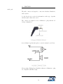


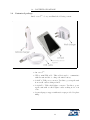
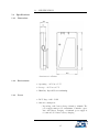

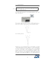


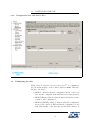


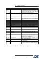
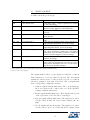


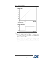
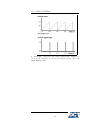

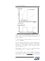
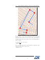


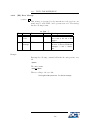
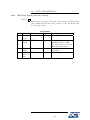
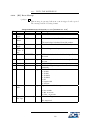
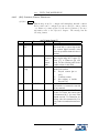


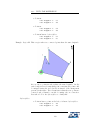

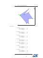
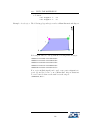
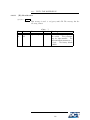

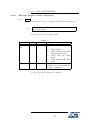


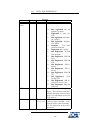

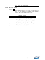


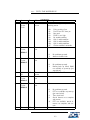
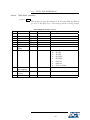

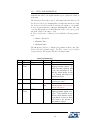
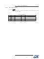

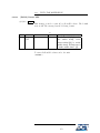


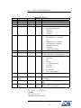

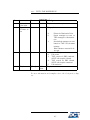
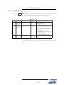

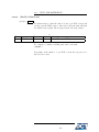
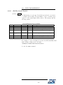


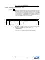
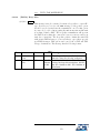

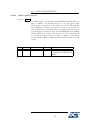
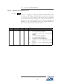
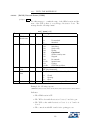
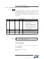

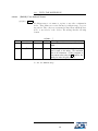

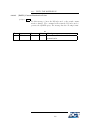
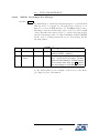
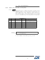
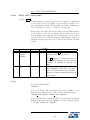


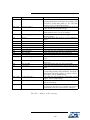
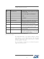

![Antares SB-GSM User`s Manual [FW5.21]](http://vs1.manualzilla.com/store/data/005969322_1-cafecc5f2ef16fdcdd0cbc825ff9e000-150x150.png)
![Antares SB-GSM User`s Manual [FW5.30]](http://vs1.manualzilla.com/store/data/005924073_1-5fee82d33b9684441f88f249063588d6-150x150.png)