1
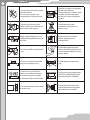
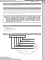
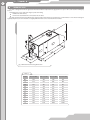
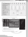
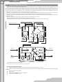
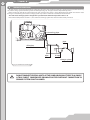
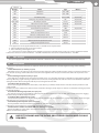
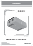
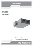
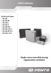
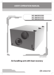
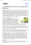
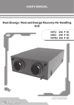
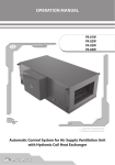
USER’S MANUAL VUT 800 WH VUT 1000 WH VUT 1500 WH VUT 2000 WH HEAT RECOVERY AIR HANDLING UNIT 2 CONTENTS Safety requirements 3 Introduction 5 Use 5 Delivery set 5 Designation key 5 Technical data 6 Unit design and operating logic 12 Mounting and set-up 13 Condensate drainage 16 Functional diagram 17 Connection to power mains 18 Unit control 19 Maintenance 19 Fault handling 20 Storage and transportation rules 20 Manufacturer's warranty 21 Acceptance certificate 22 Seller information 22 Connection certificate 22 Warranty card 23 3 SAFETY REQUIREMENTS Read the user’s manual carefully prior to the operation and installation of the heat recovery air handling unit. Fulfill the operation manual requirements as well as the provisions of all the applicable local and national construction, electrical and technical codes and standards. The warnings contained in the user’s manual must be considered most seriously since they contain vital personal safety information. Failure to follow the safety requirements may result in an injury or unit damage. Read the manual carefully and keep it as long as you use the unit. While transferring the unit control the control panel user’s manual must be turned over to the receiving operator. Symbol legend used in the manual: WARNING! DO NOT! UNIT MOUNTING AND OPERATION SAFETY PRECAUTIONS The unit must be disconnected from power supply prior to any installation or repair operation. The unit must be grounded! The unit must not be operated outside the temperature range stated in the user's manual and in aggressive or explosive environments. Do not use damaged equipment or conductors to connect the unit to power mains. While installing the unit follow the safety regulations specific to the use of electric tools. Unpack the unit with care. Do not change the power cable length at your own discretion. Do not bend the power cable. Avoid damaging the power cable. Do not position any heating devices or other equipment in close proximity to the unit power cable. 4 Do not touch the unit controls with wet hands. Do not carry out the unit maintenance with wet hands. Use the unit only as intended by the manufacturer. Do not connect a clothes dryer or other similar equipment to the unit or the ventilation system. Do not wash the unit with water. Protect the unit electric parts from water ingress. Do not put any water containers on the unit, i.e. flower vases. Keep combustible gases and inflammable products away of the unit. ON OFF Disconnect the unit from power supply prior to maintenance. Do not let children operate the unit. Do not damage the power cable while operating the unit. Do not put any objects on the power cable. Do not sit on the unit and do not put any objects on it. Do not open the operating unit. In case of unusual sounds, odours or smoke disconnect the unit from power supply and contact the service centre. During a long-term operation of the unit periodically check the mounting for reliability. Do not block the air duct when the unit is on. Do not let air flow from the unit be directed to the open flame devices or candles. 5 INTRODUCTION This user’s manual includes technical description, operation, installation and mounting guidelines, technical data for the heat recovery air handling unit VENTS VUT … WH, hereinafter referred as the unit. USE The unit with heat recovery and a water heater is designed to save heat energy by means of heat recovery and is one of the energy saving components used in the buildings and premises. The unit is a component part and is not designed for independent operation. The unit is designed to provide permanent controlled air exchange by means of mechanical ventilation in houses, offices, hotels, cafés, meeting halls and other mechanically ventilated premises as well as utilization of extract air heat energy to warm up supply purified air. Transported air must not contain any flammable or explosive mixtures, evaporation of chemicals, coarse dust, soot and oil particles, sticky substances, fibrous materials, pathogens or any other harmful substances. THE UNIT IS NOT INTENDED TO BE USED BY CHILDREN, PHYSICALLY OR MENTALLY DISABLED PERSONS, PERSONS WITH SENSORY DISORDER, PERSONS WITH NO APPROPRIATE QUALIFICATION. ANY OPERATIONS WITH THE UNIT MUST BE PERFORMED ONLY BY PROPERLY QUALIFIED PERSONNEL AFTER THE APPROPRIATE SAFETY BRIEFING. THE UNIT INSTALLATION SITES MUST PREVENT ACCESS BY UNATTENDED CHILDREN. DELIVERY SET Unit - 1 item Wall-mounted control panel - 1 item User’s manual - 1 item Control panel user’s manual - 1 item Packing box - 1 item DESIGNATION KEY VUT Х WH-X-X Modification (VUT 1500 WH, VUT 2000 WH) L - left R - right Number of water heating coils 2, 4 Spigot orientation H - horizontal Heater type W - water heater Air capacity [m 3/h] 800, 1000, 1500, 2000 Unit type VUT - ventilation with heat recovery 6 TECHNICAL DATA The unit is designed for indoor application with the ambient temperature ranging from +1°C up to +40°C and relative humidity up to 80 %. Hazardous parts access and water ingress protection rating: IP 44 for the unit motors; IP 22 for the assembled unit connected to the air ducts. The unit overall and connecting dimensions, external view, technical data are shown in Fig. 1 and in Tables 1 and 2. The unit design is regularly improved, so some models can slightly differ from those ones described in this manual. Fig. 1. Overall and connecting dimensions Table 1 Model VUT 800 WH VUT 1000 WH VUT 1500 WH VUT 2000 WH ØD 249 249 314 314 B 613 613 842 842 B1 460 460 581 581 B2 306 306 320 320 B3 386 386 520 520 H 698 698 814 814 H1 832 832 947 947 H2 154 154 201 201 H3 280 280 595 595 L 1071 1071 1345 1345 L1 1117 1117 1388 1388 L2 1171 1171 1445 1445 7 Table 2 Model VUT 800 WH-2 VUT 800 WH-4 VUT 1000 WH-2 VUT 1000 WH-4 Voltage, 50 Hz [V] VUT 1500 WH-2 VUT 1500 WH-4 VUT 2000 WH-2 4 2 VUT 2000 WH-4 1 ~ 230 Number of water heating coils 2 4 2 4 2 4 Total unit power [kW] 0,49 0,82 0,98 1,30 Total unit current [A] 2,16 3,6 4,3 5,68 Max. air capacity [m /h] 780 1100 1700 2100 Rotation speed [min-1] 1650 1850 1100 1150 Noise level, 3 m [dB(A)] 48 60 49 65 -25 up to +45 -25 up to +40 -25 up to +45 -25 up to +40 3 Max. transported air temperature [°C] Casing material Aluzinc Insulation 50 mm mineral wool extract Filter: G4 supply Connected duct diameter [mm] G4 (F7-optional) Ø 250 Ø 315 88 99 Weight [kg] Heat recovery efficiency up to 78 % up to 77 % Heat exchanger type Cross flow Heat exchanger material Aluminium Performance chart for the VUT 800 WH-2 water heater parameters is shown in Fig. 2. VUT 800 WH-2 Coil heating capacity [kW] External air temperature [°C] Air temperature at outlet from the heater [°C] Water heater parameters calculation example: Air Speed. Starting from 950 m3/h on the air flow scale draw a vertical line till the air speed axis which makes 3.35 m/s. Water pressure drop [kPa] Air speed inside the heater [m/s] Air flow through the heater [m3/h] Supply air temperature. Prolong the line up to the point where it crosses the outside air temperature (descending curve, e.g. -15°C) then draw a horizontal line from this point to the left till crossing water in/out temperature curve (e.g. 90/70). From this point draw a vertical line to the supply air temperature axis on top of the graphic (23 °C). Heating coil capacity. Prolong the line up to the point where it crosses the outside air temperature (ascending curve, e.g. -15°C) and draw a horizontal line from this point to the right until it crosses water in/out temperature curve (e.g. 90/70), from here draw a vertical line up to the scale representing the heating coil capacity (13.5 kW). Water flow. Prolong the line down to water flow axis at the bottom of the graphic (0.14 l/s). Water pressure drop. Draw the line from the point where line crosses the black curve to the pressure drop axis. (1.5 kPa). Fig. 2 Calculation of the VUT 800 WH-2 water heater parameters Water flow through the water heating coils [l/s] 8 Performance chart for the VUT 800 WH-4 water heater parameters is shown in Fig. 3. VUT 800 WH-4 Coil heating capacity [kW] External air temperature [°C] Air temperature at outlet from the heater [°C] Water pressure drop [kPa] Air speed inside the heater [m/s] Air flow through the heater [m3/h] Water heater parameters calculation example: Air Speed. Starting from 950 m3/h on the air flow scale draw a vertical line till the air speed axis which makes 3.35 m/s. Supply air temperature. Prolong the line up to the point where it crosses the outside air temperature (descending curve, e.g. -15°C) then draw a horizontal line from this point to the left till crossing water in/out temperature curve (e.g. 70/50). From this point draw a vertical line to the supply air temperature axis on top of the graphic (29 °C). Heating coil capacity. Prolong the line up to the point where it crosses the outside air temperature (ascending curve, e.g. -15°C) and draw a horizontal line from this point to the right until it crosses water in/out temperature curve (e.g. 70/50), from here draw a vertical line up to the scale representing the heating coil capacity (16 kW). Water flow. Prolong the line down to water flow axis at the bottom of the graphic (0.2 l/s). Water flow through the water heating coils [l/s] Water pressure drop. Draw the line from the point where line crosses the black curve to the pressure drop axis. (2.1 kPa). Fig. 3 Calculation of the VUT 800 WH-4 water heater parameters Performance chart for the VUT 1000 WH-2 water heater parameters is shown in Fig. 4. VUT 1000 WH-2 Coil heating capacity [kW] External air temperature [°C] Air temperature at outlet from the heater [°C] Water heater parameters calculation example: Water pressure drop [kPa] Air speed inside the heater [m/s] Air flow through the heater [m3/h] Air Speed. Starting from 950 m3/h on the air flow scale draw a vertical line till the air speed axis which makes 3.35 m/s. Supply air temperature. Prolong the line up to the point where it crosses the outside air temperature (descending curve, e.g. -15°C) then draw a horizontal line from this point to the left till crossing water in/out temperature curve (e.g. 90/70). From this point draw a vertical line to the supply air temperature axis on top of the graphic (23 °C). Heating coil capacity. Prolong the line up to the point where it crosses the outside air temperature (ascending curve, e.g. -15°C) and draw a horizontal line from this point to the right until it crosses water in/out temperature curve (e.g. 90/70), from here draw a vertical line up to the scale representing the heating coil capacity (13.5 kW). Water flow. Prolong the line down to water flow axis at the bottom of the graphic (0.14 l/s). Water pressure drop. Draw the line from the point where line crosses the black curve to the pressure drop axis. (1.5 kPa). Fig. 4 Calculation of the VUT 1000 WH-2 water heater parameters Water flow through the water heating coils [l/s] 9 Performance chart for the VUT 1000 WH-4 water heater parameters is shown in Fig. 5. VUT 1000 WH-4 Coil heating capacity [kW] External air temperature [°C] Air temperature at outlet from the heater [°C] Water heater parameters calculation example: Air Speed. Starting from 950 m3/h on the air flow scale draw a vertical line till the air speed axis which makes 3.35 m/s. Water pressure drop [kPa] Air speed inside the heater [m/s] Air flow through the heater [m3/h] Supply air temperature. Prolong the line up to the point where it crosses the outside air temperature (descending curve, e.g. -15°C) then draw a horizontal line from this point to the left till crossing water in/out temperature curve (e.g. 70/50). From this point draw a vertical line to the supply air temperature axis on top of the graphic (29 °C). Heating coil capacity. Prolong the line up to the point where it crosses the outside air temperature (ascending curve, e.g. -15°C) and draw a horizontal line from this point to the right until it crosses water in/out temperature curve (e.g. 70/50), from here draw a vertical line up to the scale representing the heating coil capacity (16 kW). Water flow. Prolong the line down to water flow axis at the bottom of the graphic (0.2 l/s). Water flow through the water heating coils [l/s] Water pressure drop. Draw the line from the point where line crosses the black curve to the pressure drop axis. (2.1 kPa). Fig. 5 Calculation of the VUT 1000 WH-4 water heater parameters Performance chart for the VUT 1500 WH-2 water heater parameters is shown in Fig. 6. VUT 1500 WH-2 Coil heating capacity [kW] External air temperature [°C] Air temperature at outlet from the heater [°C] Water heater parameters calculation example: Air Speed. Starting from 2000 m3/h on the air flow scale draw a vertical line till the air speed axis which makes 3.75 m/s. Water pressure drop [kPa] Air speed inside the heater [m/s] Air flow through the heater [m3/h] Supply air temperature. Prolong the line up to the point where it crosses the outside air temperature (descending curve, e.g. -15°C) then draw a horizontal line from this point to the left till crossing water in/out temperature curve (e.g. 90/70). From this point draw a vertical line to the supply air temperature axis on top of the graphic (22 °C). Heating coil capacity. Prolong the line up to the point where it crosses the outside air temperature (ascending curve, e.g. -15°C) and draw a horizontal line from this point to the right until it crosses water in/out temperature curve (e.g. 90/70), from here draw a vertical line up to the scale representing the heating coil capacity (28 kW). Water flow. Prolong the line down to water flow axis at the bottom of the graphic (0.35 l/s). Water pressure drop. Draw the line from the point where line crosses the black curve to the pressure drop axis. (3.8 kPa). Fig. 6 Calculation of the VUT 1500 WH-2 water heater parameters Water flow through the water heating coils [l/s] 10 Performance chart for the VUT 1500 WH-4 water heater parameters is shown in Fig. 7. VUT 1500 WH-4 Coil heating capacity [kW] External air temperature [°C] Air temperature at outlet from the heater [°C] Water heater parameters calculation example: Air Speed. Starting from 2000 m3/h on the air flow scale draw a vertical line till the air speed axis which makes 3.75 m/s. Water pressure drop [kPa] Air speed inside the heater [m/s] Air flow through the heater [m3/h] Supply air temperature. Prolong the line up to the point where it crosses the outside air temperature (descending curve, e.g. -15°C) then draw a horizontal line from this point to the left till crossing water in/out temperature curve (e.g. 70/50). From this point draw a vertical line to the supply air temperature axis on top of the graphic (31 °C). Heating coil capacity. Prolong the line up to the point where it crosses the outside air temperature (ascending curve, e.g. -15°C) and draw a horizontal line from this point to the right until it crosses water in/out temperature curve (e.g. 70/50), from here draw a vertical line up to the scale representing the heating coil capacity (35 kW). Water flow. Prolong the line down to water flow axis at the bottom of the graphic (0.43 l/s). Water flow through the water heating coils [l/s] Water pressure drop. Draw the line from the point where line crosses the black curve to the pressure drop axis. (9 kPa). Fig. 7 Calculation of the VUT 1500 WH-4 water heater parameters Performance chart for the VUT 2000 WH-2 water heater parameters is shown in Fig. 8. VUT 2000 WH-2 Coil heating capacity [kW] External air temperature [°C] Air temperature at outlet from the heater [°C] Water heater parameters calculation example: Air Speed. Starting from 2000 m3/h on the air flow scale draw a vertical line till the air speed axis which makes 3.75 m/s. Water pressure drop [kPa] Air speed inside the heater [m/s] Air flow through the heater [m3/h] Supply air temperature. Prolong the line up to the point where it crosses the outside air temperature (descending curve, e.g. -15°C) then draw a horizontal line from this point to the left till crossing water in/out temperature curve (e.g. 90/70). From this point draw a vertical line to the supply air temperature axis on top of the graphic (22 °C). Heating coil capacity. Prolong the line up to the point where it crosses the outside air temperature (ascending curve, e.g. -15°C) and draw a horizontal line from this point to the right until it crosses water in/out temperature curve (e.g. 90/70), from here draw a vertical line up to the scale representing the heating coil capacity (28 kW). Water flow. Prolong the line down to water flow axis at the bottom of the graphic (0.35 l/s). Water pressure drop. Draw the line from the point where line crosses the black curve to the pressure drop axis. (3.8 kPa). Fig. 8 Calculation of the VUT 2000 WH-2 water heater parameters Water flow through the water heating coils [l/s] 11 Performance chart for the VUT 2000 WH-4 water heater parameters is shown in Fig. 9. VUT 2000 WH-4 Coil heating capacity [kW] External air temperature [°C] Air temperature at outlet from the heater [°C] Water heater parameters calculation example: Air Speed. Starting from 2000 m3/h on the air flow scale draw a vertical line till the air speed axis which makes 3.75 m/s. Water pressure drop [kPa] Air speed inside the heater [m/s] Air flow through the heater [m3/h] Supply air temperature. Prolong the line up to the point where it crosses the outside air temperature (descending curve, e.g. -15°C) then draw a horizontal line from this point to the left till crossing water in/out temperature curve (e.g. 70/50). From this point draw a vertical line to the supply air temperature axis on top of the graphic (31 °C). Heating coil capacity. Prolong the line up to the point where it crosses the outside air temperature (ascending curve, e.g. -15°C) and draw a horizontal line from this point to the right until it crosses water in/out temperature curve (e.g. 70/50), from here draw a vertical line up to the scale representing the heating coil capacity (35 kW). Water flow. Prolong the line down to water flow axis at the bottom of the graphic (0.43 l/s). Water pressure drop. Draw the line from the point where line crosses the black curve to the pressure drop axis. (9 kPa). Fig. 9 Calculation of the VUT 2000 WH-4 water heater parameters Water flow through the water heating coils [l/s] 12 UNIT DESIGN AND OPERATING LOGIC The unit has the following operating logic (Fig. 10): Warm stale extract air from the room flows through the air ducts to the unit, is purified in the extract filter, supplied to the heat exchanger and exhausted outside by the exhaust fan. Clean cold air from outside is moved by supply fans to the unit where from it is directed to the supply filter. Then cleaned air flows through the heat exchanger and is supplied to the room through the air ducts. Heat energy of warm extract air is transferred to clean intake fresh air from outside and warms it up. Heat recovery minimizes heat losses, energy demand and operating costs for warming up supply air in cold seasons. The unit is a framework construction that includes a frame made of six rigidly fixed 50 mm thick sandwich panels. The three-layer sandwich panels are made of two galvanized sheets, internally filled with heat- and sound-insulated mineral wool layer. The air handling unit is equipped with quick-detachable service panels for scheduled repair and maintenance operations. The panels are specially sealed. There is a control unit on the top panel of the unit, where the terminal box is located. The cables must be routed to the terminal box through the cable lead-ins. The wiring diagram for connection of the unit to power mains is shown on the inner side of the control unit. extract filter electronic control block wall remote control panel plate cross-flow heat exchanger supply air filter supply fan water heater extract fan bypass condensate drain pan drain pipe extract air intake air supply air exhaust air Fig. 10 Unit design and operating logic The unit basic modification includes: external wall-mounted control panel that is connected to the control system via a cable; supply and extract fan with forward curved blades and maintenance-free external rotor motors with integrated overheating protection; plate cross-flow heat exchanger; water heater; supply filter with G4 filter class (F7 is optional); extract filter with G4 filter class. 13 MOUNTING AND SET-UP The unit may be suspended on a threaded rod that is fixed inside a dowel or may be rigidly fixed on a horizontal plane (Fig.11). While mounting the unit provide enough access for unit servicing and maintenance. The minimum distances from the unit to the mounting planes is shown in Fig.12. Example Nut Washer Vibration damping rubber Nut and lock-nut Unit mounting on a horizontal plane Fig. 11 Unit mounting А А= min 600 mm for VUT 800 (1000) WH А= min 820 мм VUT 1500 (2000) WH Fig. 12. Minimum mounting distances 14 VUT 1500 WH and VUT 2000 WH UNITS MODIFICATIONS depending on the service side Left- and right-handed modifications are provided for ease of mounting and maintenance: Left-handed modification EXTRACT AIR INTAKE AIR Service side SUPPLY AIR EXHAUST AIR Right-handed modification INTAKE AIR EXTRACT AIR Service side EXHAUST AIR SUPPLY AIR Safety precautions: The unit must be mounted to a rigid and stable structure. Check the technical parameters and the unit weight. The unit must be suspended using anchor bolts. Before starting mounting check that the mounting structure has sufficient loading capacity for the unit weight, otherwise reinforce it with beams, etc. After that fix the bolts. If the construction strength or surface is not rigid enough it can resonate with the unit and create abnormal noise and vibration. While mounting the unit provide enough service space and an access door in the ceiling for inspection and maintenance of the filters, heat exchanger and fans. One access door is required for each unit. For details, refer the outline drawing (ref. Fig. 1). Insert the anchor bolt inside the mount for the fixing bracket and fix it with nuts and washers. Make sure the unit casing has no foreign objects inside, like paper and foil. If the bolts used for the unit mounting are too short the unit can generate abnormal noise and resonate with the ceiling. If the connection point to the spiral seam duct is supposed to be the source of the abnormal noise, install a flexible air duct instead of the spiral seam one. The precautions referred above are normally sufficient to solve the resonance problem. For the better effect you may use anti-vibration connectors. To ensure the best performance of the unit provide a straight 1 m duct section on both sides of the unit while mounting . Access to the unit must be prevented by installing a protecting grille or any other device with the mesh width up to 12.5 mm. In order to attain maximum power the water heater should be counter-flow connected (Fig. 13). All calculation diagrams (ref. Fig. 2-9, page 5-9) are valid for the counter-flow connection of the water heater. In case of the directflow connection the water heater has lower power but higher frost-resistant properties. а) direct-flow connection Fig. 13. Water heat connection b) counter-flow connection 15 Mixing unit diagram (not included into delivery set) of the water heater is shown in Fig. 14. 1 Mixing unit diagram 3 4 2 2 6 M 7 5 8 1. Water heater. 2. Shutoff valves. 3. Circulation pump. 4. Bypass damper. 5. Boiler. 6. Heat medium regulating valve. 7. Non-return valve. 8. Coarse filter. Heat medium regulating valve actuator Fig. 14. Mixing unit diagram 16 CONDENSATE DRAINAGE The unit must be connected to the drainage system (Fig. 15). Connect the condensate drain pipe , the U-trap (not included into delivery set) and the sewage system with metal, plastic or rubber pipes (Fig. 15). The pipes must be sloped down by min. 3 °. Before starting the unit fill the system with water and check that the U-trap is always filled with water. Make sure that the water drainage is correct. Wrong connection to sewage system may result in condensate accumulation inside the unit. The condensate drainage system is designed for operation at the ambient temperature above 0 °C! If the ambient temperature is below 0 °C, the condensate drainage system must be heat insulated and pre-heated. min 3° connecting pipe pipe pipe 70 140 dain pipe; U-trap sewage system Fig. 15. Condensate drainage DO NOT CONNECT SEVERAL UNITS OF THE SAME OR VARIOUS TYPES TO A SINGLE U-TRAP. DIRECT CONDENSATE DRAINAGE OUTSIDE WITHOUT CONNECTION TO SEWAGE SYSTEM IS NOT ALLOWED. 17 FUNCTIONAL DIAGRAM OUTSIDE Power supply INSIDE 3 Digital input (DI) Digital output (DO) Analogue input (AI) Analogue output (AO) Fig. 16. Functional diagram Table 3 Designation Name Designation Name SM1 Supply damper actuator M1 Supply fan SM2 Extract damper actuator M2 Extract fan SM3 Heat exchanger damper actuator M3 Circulation pump SM4 Heat medium regulating valve actuator F1 Supply filter TE1 Intake air temperature sensor F2 Extract filter TE2 Temperature sensor at downstream of the heat exchanger D1 Supply air damper TE3 Return heat medium temperature sensor D2 Extract air damper TE4 Water heater freeze protection sensor Q1 Water heater TE5 Supply air temperature sensor Q2 Cooler DD1 Pump dry run protection relay RK1 Plate heat exchanger P1 Control panel 18 CONNECTION TO POWER MAINS CONNECTION OF THE UNIT TO POWER MAINS IS ALLOWED BY A QUALIFIED ELECTRICIAN WITH A WORK PERMIT FOR THE ELECTRIC UNITS UP TO 1000 V AFTER CAREFUL READING OF THE PRESENT USER’S MANUAL. THE RATED ELECTRICAL PARAMETERS OF THE UNIT ARE SHOWN ON THE RATING PLATE. ANY INTERNAL CONNECTION MODIFICATIONS ARE NOT ALLOWED AND RESULT IN WARRANTY LOSS. The unit is rated for connection to 230 V / 50 Hz single-phase alternating current power mains (Fig. 17, 18) via insulated, durable and heat resistant conductors (cables, wires) with respective cross section, in any case no less than 2.5 mm2. The above cross section is for reference only. The applicable cable cross section must be selected depending on the wire type, its maximum temperature and insulation, the maximum current, the wire length and its installation method. Use copper wires only. The unit must be grounded. Connect the unit to power mains through the terminal block which is located in the control unit on the top of the unit, in compliance with the wiring diagram and the terminal marking. Connect all the control and supply cables in compliance with the terminal marking and polarity! Connect the unit to power mains through the external automatic switch with thermal-magnetic circuit breaker integrated into the fixed wiring system. The trip current should be not lower than the current consumption (ref. Table 2). X1 1 2 3 4 5 6 7 8 9 10 11 12 13 14 15 16 17 18 19 20 21 22 23 24 25 26 27 28 29 30 31 32 33 34 35 L N PE L N PE PE N L 1 2 c no nc c no 1 2 3 6 5 1 9 2 3 4 7 1 2 1 2 1 1 2 1 3 2 1 2x1 mm L N PE 1 2 N L SM2 Y U DD1* P1* AC208EM2+LP PK1* t°C M2* + t°C M2 - SM4* t°C L t°C N SM1 M1 2 1 2 1 1 2 3 5 6 5 1 9 2 3 4 7 8 1 2 1 2 1 2 1 2 1 2 1 2 3 1 2 t°C PE N L Cooler activation signal (no-contact) Power 230 V AC U1U2 PE Z U1U2 PE Z TE1 TE2 TE3 TE4 TE5 L L1 N SM3 — ELECTRIC SHOCK HAZARD! Fig. 17. External wiring diagram for VUT 800 (1000) WH X1 1 2 3 4 5 6 7 8 9 10 11 12 13 14 15 16 17 18 19 20 21 22 23 24 25 26 27 28 29 30 31 32 33 34 35 36 37 38 L N PE L N PE L N PE PE N L 1 2 c no nc c no 1 2 3 6 5 1 9 2 3 4 7 1 2 1 2 1 1 2 1 3 2 1 2x1 mm L N PE 1 2 N SM2 L DD1* Y U P1* AC208EM2+LP PK1* t°C M2* + t°C M2 - SM4* t°C L t°C N SM1 M1 2 1 2 1 1 2 3 5 6 5 1 9 2 3 4 7 8 1 2 1 2 1 2 1 2 1 2 1 2 3 1 2 t°C PE N L Cooler activation signal (no-contact) Power 230 V AC U1U2 PE Z U1U2 PE Z TE1 TE2 TE3 TE4 TE5 L L1 N SM3 — ELECTRIC SHOCK HAZARD! Fig. 18. External wiring diagram for VUT 1500 (2000) WH ATTENTION! MOUNTING AND CONNECTING OF THE AUTOMATIC CONTROL SYSTEM IS ALLOWED BY A QUALIFIED ELECTRICIAN WITH A WORK PERMIT FOR THIS TYPE OF OPERATIONS. DISCONNECT THE UNIT FROM POWER MAINS BEFORE ANY SERVICING OR MAINTENANCE OPERATIONS. 19 Table 4 Design. Name Type M1 Supply fan max. 1 кW M2 Extract fan max. 1 kW M3* Circulation pump max. 0.3 kW 3х0,75 mm2 DD1* Pump dry run protection relay**** NC 2х0,75 mm2 SM1*, SM2 Air damper actuator LF 230 2х0,75 mm2 SM4* Water heater valve actuator LR 24 SR 3х0,75 mm2 SM3 Heat exchanger bypass damper actuator LM 230 PK1* Contact from fire alarm panel NO P1* Control panel** SAS908PIT TE1 Intake air temperature sensor ST-01 TE2 Exhaust air temperature sensor STa-02 TE3 Return heat medium temperature sensor STw-02 TE4 Water heater freeze protection sensor STw-02 TE5 Supply air temperature sensor STa-02 Wire*** 2х0,75 mm2 * - The appliances are not supplied with the unit, are available on the separate order. ** - Cable length from P1 must not exceed 10 meters. ** - Max. connecting cable length is 20 m! **** - The system can operate without a heat medium pressure relay in the DD1 heater, in this case a jumper should be installed between the contacts 11 and 12 for VUT 800…1000 WH or between the contacts 14 and 15 for VUT 1500…2000 WH. UNIT CONTROL The unit is equipped with a built-in electronic automatic control unit and a control panel (ref. Control panel user’s manual). MAINTENANCE Maintenance operations of the unit are required 3-4 times per year. Maintenance includes regular cleaning and the following operations: 1. Filter maintenance (3-4 times per year). Dirty filters increase air resistance in the system and reduce supply air volume. The filters require cleaning not less than 3-4 times per year. Vacuum cleaning is allowed. After two consecutive cleanings filters must be replaced. Contact the unit Seller to purchase new filters. 2. Heat exchanger inspection (once per year). Some dust may accumulate on the heat exchanger block even in case of regular maintenance of the filters. To maintain the high heat exchange efficiency, regular cleaning is required. To clean the heat exchanger pull it out of the unit and clean it with flush it with warm detergent solution. After cleaning install the dry heat exchanger back to the unit. 3. Fan inspection (once per year). Even in case of regular maintenance of the filters, some dust may accumulate inside the fans and reduce the fan performance and supply air flow. Clean the fans with a soft brush or cloth. No water and abrasive detergent, sharp objects or solvents are allowed for cleaning to prevent the impeller damage. 4. Condensate drainage inspection (once per year). The drain pipes may get clogged with the extracted particles. Pour some water inside the drain pan to check the pipe for clogging. Clean the U-trap and the drain pipe if required. 5. Supply air flow control (twice per year). Leaves and other pollutions can clog the supply air grille and reduce the unit performance and supply air volume. Check the supply grille twice per year and clean it as required. 6. Ductwork system inspection (once in 5 years). Even if you follow all the listed maintenance guidelines, some dust can get accumulated inside the air ducts and reduce the unit performance. Duct maintenance means regular cleaning or replacement. 5. Exhaust louvre shutters and intake diffusers cleaning (as required). Remove the diffusers and the grilles and wash them with warm water and mild detergent solution. Do not change locations of the diffusers and the louvre shutters. INSPECT THE HOOD AND THE INTAKE GRILLE ONCE PER YEAR AND CLEAN AS REQUIRED. 20 FAULT HANDLING Table 5 Faults and fault handling Problem The fan(s) do(es) not get started. Automatic circuit breaker tripping. Low air flow. Cold supply air. High noise, vibration. Water leakage. Possible reasons Fault handling No power supply. Make sure the power supply line is connected correctly, otherwise troubleshoot the connection error. Motor is jammed, the blades are soiled. Turn the unit off. Troubleshoot the motor jamming. Clean the blades. Restart the unit. Alarm in the system. Remove the system alarm. Restart the unit. High current consumption due to short circuit in power line. Turn the unit off. Contact the service centre. Low set air flow. Switch the unit to higher speed. Filters, fans or the heat exchanger are soiled. Clean or replace the filters; clean the fan(s) and the heat exchanger. The ventilation system components (air ducts, Clean or replace the ventilation system components (air ducts, diffusers, diffusers, louvre shutters, grilles) are soiled or louver shutters, grilles). damaged. Air dampers, diffusers or louvre shutters are closed. Make sure that the air dampers, diffusers or louver shutters are fully opened. The extract filter is soiled. Clean or replace the extract filter. The heat exchanger is frozen. Check the heat exchanger for freezing. Turn the unit off if required and restart it after the freezing danger is no longer imminent. Malfunction of the water heater. Contact the service centre. The impeller(s) is clogged. Clean the impeller(s). Loose screw tightening. Tighten the screws. No anti-vibration mounts. Install the rubber anti-vibration mounts (not included into delivery set). The drainage system is soiled, damaged or Clean the drainage system. Check the drain line slope angle. Make sure arranged not correctly. that the U-trap is filled with water and the drain pipes are frost protected. STORAGE AND TRANSPORTATION RULES Store the unit in the manufacturer’s original packing box in a closed ventilated premise with temperature range from +10°C to + 40°C and relative humidity maximum 60% (at +20°C). Vapours or particles which can cause corrosion or damage the insulation or connection tightness are not allowed in the storage environment. Use hoist machinery for handling and transportation to prevent possible mechanical damages of the unit. Fulfill the requirements for transportation of the specified cargo type during cargo-handling operations. Use any vehicle types for the unit transportation provided that it is protected against mechanical or weather damage. Avoid any mechanical shocks and strokes during handling operations. 21 MANUFACTURER’S WARRANTY The manufacturer hereby warrants normal operation of the unit over the period of 24 months from the retail sale date provided the user’s observance of the transportation, storage, installation and operation regulations. Should any malfunctions occur during the unit operation due to manufacturer’s fault during the warranty period the user is entitled to elimination of faults by means of warranty repair performed by the manufacturer. The warranty repair includes work specific to elimination of faults in the unit operation to ensure its intended use by the user within the warranty period. The faults are eliminated by means of replacement or repair of the complete unit or the faulty part thereof. The warranty repair does not include: • routine maintenance; • unit installation / dismantling; • unit setup. To benefit from warranty repair the user must provide the unit, the user’s manual with stamped sale date and the payment document certifying the purchase. The unit model must comply with the one stated in the user’s manual. Contact the unit Seller for warranty service. The manufacturer’s warranty does not apply to the following cases: • user’s failure to provide the unit with the entire delivery package as stated in the user’s manual or with missing component parts previously dismounted by the user; • mismatch of the unit model and make with the respective details stated on the unit packing and in the user’s manual; • user’s failure to ensure timely technical maintenance of the unit; • external damage to the casing (excluding external modifications of the unit as required for its installation) and the internal components of the unit; • alteration of the unit design or engineering changes of the unit; • replacement and use of the unit assemblies, parts and components not approved by the manufacturer; • unit misuse; • user’s violation of the unit installation regulations; • user’s violation of the unit management regulations; • unit connection to the power mains with a voltage different from the one stated in the user’s manual; • unit breakdown due to voltage surges in the power mains; • user’s discretionary repair of the unit; • unit repair performed by any persons not authorized by the manufacturer; • expiry of the unit warranty period; • user’s violation of the established regulations specific to the unit transportation; • user’s violation of the unit storage regulations; • wrongful acts against the unit committed by third persons; • unit breakdown due to circumstances of insuperable force (fire, flood, earthquake, war, hostilities of any kind, or blockade); • missing seals if provided by the user’s manual; • failure to provide the user’s manual with the sale date stamp; • missing payment document certifying the unit purchase. FOLLOWING THE REGULATIONS STIPULATED HEREIN WILL ENSURE A LONG AND TROUBLEFREE OPERATION OF THE UNIT. USERS’ CLAIMS SHALL BE SUBJECT TO REVIEW ONLY UPON PRESENTATION OF THE UNIT, THE PAYMENT DOCUMENT AND THE USER’S MANUAL WITH THE SALE DATE STAMP. 22 ACCEPTANCE CERTIFICATE Product Type Heat recovery air handling unit Model VUT______ WH Serial Number Manufacturing Date is compliant with the technical specifications and is hereby declared ready for service. Quality Inspector’s Stamp SELLER INFORMATION Shop name Address Phone number E-mail Sales date This is to certify delivery of the complete unit with the user's manual. The warranty terms are acknowledged and accepted. Seller’s seal Customer's signature CONNECTION CERTIFICATE VUT ___ WH heat recovery air handling unit has been connected to power mains pursuant to the requirements stated in the present user’s manual. Company name Address Phone number Installation technician's full name Installation date: Signature: This is to certify that the works specific to the unit installation has been performed in accordance with all the applicable provisions of local and national construction, electrical and technical codes and standards. The unit operates normally as intended by the manufacturer. Signature: Installation technician’s company seal 23 WARRANTY CARD Product type Model Heat recovery air handling unit VUT______WH Serial number Manufacturing date Sales date Warranty period Sales company Seller’s seal NOTES _________________________________________________________________________________________________ _________________________________________________________________________________________________ _________________________________________________________________________________________________ _________________________________________________________________________________________________ _________________________________________________________________________________________________ _________________________________________________________________________________________________ _________________________________________________________________________________________________ ________________________________________________________________________________________ V45-1EN-06