1
Ordering information
1. Ordering information
SS4: 6DD1688-0AD0
Interface board SS4
2. Description
Board SS4 is an interface board for DUST protocols. Corresponding to the specific configuration, it is
inserted in one of the three CS7 module slots. A maximum of three boards per carrier module can be
inserted.
The interface board has two serial interfaces. The configured DUST protocol can run on one
interface, and the second interface is used as service interface. The hex monitor runs on this
interface in the background. Both interfaces are available at the 26-pin sub D socket connector X5.
The following protocols can be configured on the DUST interface:
DUST1
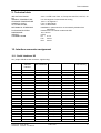
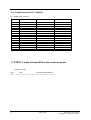
Both interfaces are RS232 ( V24 ). If another physical interface is required for the DUST protocol, an
adaption to the 40-pin X51 connection can be realized by using an interface hybrid. If handshake
signals are required for operation via the RS232 interface, the S2 interface hybrid must be inserted. In
this case, there is a different pin assignment at connector X5 than for the standard RS232 interface.
The connection to the carrier module is realized via the parallel CS7-SS4/SS5 interface at the 48-pin
plug connector X1. In addition to the data-, address- and control bus, this connection is used to
establish the +5V, +15V and -15V board power supplies. Data transfer with the processor boards is
realized via a 16-kbyte dual port RAM, which is located on the carrier module.
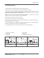
A double test socket and double LED, assigned to each slot, are provided on the carrier module.
The LEDs have the following function:
LEDs
Function
H10 / H20 / H30
H11 / H21 / H31
dark
flashing
flashing
dark
flashing
dark
lit
lit
dark
dark
lit
lit
Processor not initialized
RAM test fault
SS4 initialized, waits for initialization from the
host
DUST initialized
Data transfer running
Software error
In addition to the reset function using the power supply, a local reset can be initiated by shortcircuiting the two test sockets at the processor of the appropriate interface board. This function has no
effect on the remaining subrack sections. It is necessary for testing the software and troubleshooting;
during standard operation, it is not permissible that a reset is initiated at these sockets.
Four LEDs on the interface module indicate the signal level of the send- and receive channels of the
two serial interfaces. They are used for troubleshooting and start-up and are not externally visible
under standard operating conditions with the board inserted. They have the following function:
Siemens AG Dk-Nr. 247341
SIMADYN D Hardware User Manual
Edition 05.95
3