1
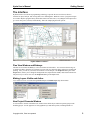
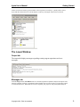
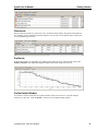
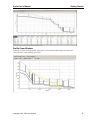
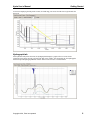
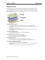
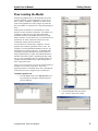
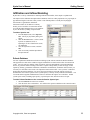
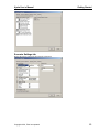
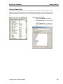
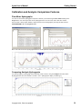
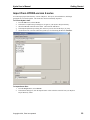
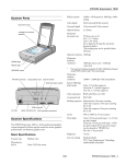
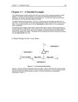
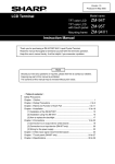
Hydra® User Manual
Getting Started
Hydra User’s Manual: Getting Started
Information in this document is subject to change without notice. No part of this
document may be reproduced or transmitted in any form or by any means, electronic, or
mechanical, for any purpose, without the express written permission of Pizer
Incorporated.
© Copyright 2014, Pizer Incorporated. All rights reserved.
Hydra is a registered trademark of Pizer Incorporated. HydraGraphics and GISMaster
are trademarks of Pizer Incorporated. All other brand and product names are trademarks
or registered trademarks of their respective holders.
Pizer Incorporated
503 N 36th St, Suite A
Seattle, WA 98103
U.S.A.
HYDRA®
Software for the Analysis, Design, and Management of
Storm, Sanitary, and Combined Sewer Systems
Version 7
Hydra User’s Manual:
Getting Started
Pizer Incorporated
503 N 36th Street, Suite A
Seattle, WA 98103
U.S.A.
Table of Contents
The Interface ...................................................................... 2
The Lower Window ............................................................. 3
Graphical Layers ................................................................. 7
Drawing Capability .............................................................. 8
Flow Loading the Model ..................................................... 9
Rainfall Data & Stormwater .............................................. 10
Infiltration and Inflow Modeling ....................................... 11
Analysis Scenarios............................................................. 12
Queries and Selection Sets ............................................... 15
Hydraulic Analysis Results ................................................ 17
Calibration and Analysis Comparison Features ................ 21
Import from HYDRA version 6 series ................................ 22
Hydra 7 Database ............................................................. 23
Hydra User’s Manual
Getting Started
The Interface
Hydra® software uses the latest programming technology to provide the user an efficient, effective
interface for input, analysis, and viewing their sewer modeling data. While the version 7 program concepts
are rooted in Hydra’s program history which dates back to the late 1960’s, everything has been improved to
give users more power, features, and flexibility, while also simplifying the menu system.
Hydra software version 7
Plan View Window and Birdseye
The Plan View window and Birdseye overview window are both sizable. You can resize them as large or
as small as needed to show the level of detail you need. The view menu has many options for zooming and
panning. Also, you can use your mouse scroll wheel to zoom and pan. The Properties dialog box in the
Project menu, allows you to change the background color, adjust the line widths, node and arrowhead size.
The passive layer color is now set in the Properties dialog in the Layer menu.
Making Layers Visible and Active
Layer selection is now accessible through Active Layer and Visible Layer drop down menus.
New Project Elements Window
A new window to the left of the Plan View window shows all the layers and flow injection groups in the
modeling project. See the properties of each graphical layer and flow injection, including number of
Copyright 2014, Pizer Incorporated
2
Hydra User’s Manual
Getting Started
entities in each layer and the type and number of flow injections on each layer. Quickly add or remove
layers and flow injections for the current analysis scenario by clicking the selection box on the left.
The Lower Window
Output tab
The output tab displays messages regarding certain program operations and error
messages.
Messages tab
From the Project menu, Check Data looks over the data required for hydraulic analysis and reports errors,
warnings, and other messages. Dynamically linked, double click on each record to go to the input “Object”
to correct the data error. When there are no errors reported, your project is ready for hydraulic analysis.
Copyright 2014, Pizer Incorporated
3
Hydra User’s Manual
Getting Started
Defects tab
When a collection system layer is the active layer, the Defects tab provides a data grid for information on
the condition, used for infiltration and inflow analysis. You can also view the defects data in a dialog box,
or in a spreadsheet-type browser.
Profile tab
In the Profile window you can display any number of pipe (links) at a time. Adjust the link count in the
Number of Entities field. Adjust the height and width of the Profile window as necessary.
Profile Details Window
You can also view the profile data in a separate window, which you can move to a second computer
monitor if you have one. Click the Details… button to view the Profile Details window.
Copyright 2014, Pizer Incorporated
4
Hydra User’s Manual
Getting Started
Profile Zoom Window
To enlarge a portion of the pipe profile, simply draw a zoom window from the upper left corner to the
lower right corner (click and drag your mouse).
Copyright 2014, Pizer Incorporated
5
Hydra User’s Manual
Getting Started
To return to displaying the full profile extents, click and drag your mouse from the lower right towards the
upper left.
Hydrograph tab
After hydraulic analysis has been run, the hydrograph tab displays a graph of flow over time for the
collection system entity currently selected in the Plan View window. Like the Profile tab, the Hydrographs
tab has an optional Hydrograph Details window which can be moved to a second monitor.
Copyright 2014, Pizer Incorporated
6
Hydra User’s Manual
Getting Started
Graphical Layers
A Hydra modeling project may contain any number of graphical layers to represent aspects of your data.
The collection system layer is made up primarily of lines, with points to represent manholes, reservoirs,
pumps, and diversion structures. Other layers might represent land use zones, ownership parcels, sanitary
service areas, stormwater drainage basins, or building footprints. You can create a new layer in Hydra in
several different ways.
To draw the graphics in Hydra:
1. Click the New Layer button (below the File menu) and then select New Empty Layer.
2. In the New Layer dialog box, give the new layer a name and select one of the 3 layer types. Click
the Ok button.
3. Click the Active Layer button and select the layer.
4. From the Layer menu, select Edit Graphics… and use the tools in the Drawing Editor to draw
the layer graphics.
To copy an existing Hydra layer:
1. Click the New Layer button and then select Clone of Existing Layer.
2. Select the layer you want to copy.
To import a layer from a previous version of Hydra:
1. Click the New Layer button and then select From DXA File.
2. Find and select the Hydra DXA file you want to import.
To import from AutoCAD:
1. Create a DXA file using the Hydra GISMaster add-on tool for AutoCAD.
2. Click the New Layer button and then select From DXA file to import the drawing layer.
To import from an ESRI ArcGIS Shapefile:
1. Click the New Layer button and then select From Shapefile.
2. In the Layer from Shapefile dialog box, create a name, select one of the three layer types, select
the Shapefile.
3. Map any associated data fields to the appropriate Hydra required fields or user fields.
Copyright 2014, Pizer Incorporated
7
Hydra User’s Manual
Getting Started
Drawing Capability
Hydra includes basic drawing capability within the program. You can add, delete, or move pipes, or any
other graphical element on existing layers. You can also create a new empty layer and do basic drawing to
create the layer.
To switch to drawing mode:
1. From the Layer menu, select Edit Graphics….
If this is a new empty layer, first you will need to set the extents of the project map. This dialog box will
automatically appear:
Copyright 2014, Pizer Incorporated
8
Hydra User’s Manual
Getting Started
Flow Loading the Model
In Hydra any graphical layer in the model may be used to
organize the loads, or flow contributions, for any type of
flow – sanitary, stormwater, infiltration, or inflow. Each
entity on the graphical layer (line, polygon, or point) may
have any number of “injection sets” to represent grouping of
flows.
Each injection set includes its own diurnal curve (flow
pattern over time) and flow volume data. For example, you
could have an injection set to represent single-family
residential customers, and another injection set for multifamily customers. For the same area, you could also have an
injection set for office-commercial, and one for retailcommercial, and one for hotel customers.
You select how the volume data is organized. You can
organize flow volume by population, units, or area. For
example, to represent apartment buildings in an area, you
might choose to organize it this way: 75 apartment units,
averaging 2 people per apartment unit, with each person
using 65 gallons per day. Hydra will combine this data to
calculate a total daily volume. Organizing the data in this
way, it’s easy to update the flows as your data changes, for
example when the contribution per capita changes after a
water conservation effort.
Once you set up a layer how you want it, the input fields are
available for every entity in the layer. These flow
organizing features are available on any layer, including the
collection system layer, polygon layers, or point layers.
To add an injection set:
1.
From the Layer menu, select Injection Sets. The
Layer dialog box will appear, with the Injection
Sets tab displayed.
2.
Copyright 2014, Pizer Incorporated
Click the New Set button, and select a
type. Give the injection set a name.
9
Hydra User’s Manual
Getting Started
Rainfall Data & Stormwater
You can model stormwater runoff using either the SCS Method (modified Santa Barbara method), the
Rational Method, or true Hydrographic simulation (based on the Stanford Watershed approach).
Runoff Characteristic
The stormwater runoff characteristics can be added as an injection set to any graphical layer in the model.
To add a stormwater injection set to the current layer:
1. From the Layer menu, select Injection Sets. The Layer
[layername] dialog will appear.
2. Click the New Set button. Select a Storm injection set
(Rational, SCS, or Hydrologic)
3. Give the injection set a name, and click OK. When
asked, add the injection set to the current Scenario.
4. Click on an entity and input the data in the Injections tab.
Storm events
For rainfall data, you can use IDF curves (intensity-durationfrequency), single guage rainfall hyetographs, radar data, or
multiple rain gauges. A storm must be added to the current
analysis scenario to generate runoff.
To add rainfall data to the project:
1. From the Projects menu, select Storm. The Storms
dialog box will appear.
2. Click the New Storm button. Select one of the 3 types of
storm files.
3. Give the storm a name, and input the data for it in the Data tab.
To import a Hydra 6 Storm file:
1. In the Storms dialog, click on
the Import button.
2. Select a Hydra 6 format .STO
file.
To add a storm to an analysis
scenario:
1. From the Projects menu,
select Scenarios.
2. Select a scenario, then click
the Properties button.
3. In the Storms tab, select the
rain event from the drop down
box.
Copyright 2014, Pizer Incorporated
10
Hydra User’s Manual
Getting Started
Infiltration and Inflow Modeling
Hydra offers a variety of methods for modeling infiltration and inflow, from simple to sophisticated.
The simplest is the traditional assumption-based methods, which use either population, area, pipe length, or
pipe diameter/length to calculate a daily volume. This method produces a steady flow hydrograph
characteristic of groundwater infiltration.
Stormwater inflow can be added to a sanitary
model, just as it would be in a stormwater model.
You can add runoff characteristics to any graphical
layer in the model, by adding an Injection Set.
To add an injection set:
1. From the Layer menu, select Injection
Sets. The Layer [layername] dialog will
appear.
2. Click the New Set button. Select a Storm
injection set (Rational, SCS, or
Hydrologic) or the Constant Flow (FLO)
for infiltration.
3. Give the injection set a name, and click
OK.
4. Click on an entity and then input data in
the Injections tab.
Defects Database
For more sophisticated infiltration and inflow modeling, Hydra software include the Defects Database.
This approach uses data on the condition of pipes and manholes to match metered flow from actual rain
events. You can create any number of data records for each pipe and manhole to represent individual
defects, or generalize them according to flow meter. Hydra’s unique ability to track each type of flow
separately (sanitary, groundwater infiltration, rainfall-derived infiltration, stormwater inflow) means you
can easily see what data source needs to be adjusted to match metered flow. Once you have a calibrated
model using the Defects Database, you can use the powerful features of Hydra software to help you
determine the most effective plan to restore system capacity currently used by infiltration and inflow. You
can model different pipeline rehabilitation scenarios to determine the impact on overall flows. Model
system repair criteria, including repair priority, expected repair date, and effectiveness of repair.
To add a Defects Database to the current Collection System layer:
1. Select the Defects tab in the lower window.
2. Click the check box to add defects. You will have the option to add them to the current Scenario.
Copyright 2014, Pizer Incorporated
11
Hydra User’s Manual
Getting Started
Analysis Scenarios
A Scenario is a grouping of data to
represent a current or potential
condition to model. It is based on
one collection system layer, and its
properties include a variety of
design criteria data, injection sets
of flow contributions, a storm
(optional), and hydraulic analysis
settings.
You can create and save many
different scenarios using your own
naming system. One scenario is
active at a time, for editing,
modifying, analysis, and viewing.
To create a new scenario:
1. From the Project menu, select Scenario. The Scenarios dialog box appears.
2. Click New Scenario. The Scenario Properties dialog box appears.
Scenario General tab
Give the analysis scenario a short name, author and description.
Scenario Layers and Injections tab
Select layers and any needed layer intersections. Select and/or un-select individual Injection Sets.
Copyright 2014, Pizer Incorporated
12
Hydra User’s Manual
Getting Started
Scenario Settings tab
Define the analysis settings for the hydraulic calculations.
Copyright 2014, Pizer Incorporated
13
Hydra User’s Manual
Getting Started
Scenario Storms tab
Select the rain event and any delay or worst-case analysis.
Defects tab
Select the defects seasonal condition (Wet vs Dry Season), defects scenario “tags” to include, and account
for repair priority and construction date. Note that rapid infiltration (rainfall-dependent infiltration) and
stormwater inflow will only be generated if a rainfall event is selected on the Storm tab.
Copyright 2014, Pizer Incorporated
14
Hydra User’s Manual
Getting Started
Queries and Selection Sets
Quick Query
You can use the Quick Query text box to input simple data queries on the current layer. Simply select the
color for the Selection Set, and type the query statement. Each query is saved in the list for even quicker
use in the future.
Standard Query
For more complex queries, use the Query dialog box. Create a query using the tools provided, or type an
SQL statement in the text box. Go through the process any number of times using different colors each
time to create a multi-color Selection Set.
Copyright 2014, Pizer Incorporated
15
Hydra User’s Manual
Getting Started
The Update Layer Using Selection Set feature allows you to use the Selection Set to update data in the
layer table – the quickest way to input data into your project.
Any query result, or selection set, and be saved and
displayed on screen at a later time.
Copyright 2014, Pizer Incorporated
16
Hydra User’s Manual
Getting Started
Hydraulic Analysis Results
You can run a hydraulic analysis of the currently selected analysis scenario.
To do a hydraulic analysis of the current Scenario:
1.
From the Project menu, select Analyze. Or click on the Analyze button by the menu bar:
Hydrograph Results
The Hydrographs tab displays the flows throughout the analysis period. Each type of flow (sanitary,
stormwater, infiltration, and inflow) is tracked separately throughout the system. This is a unique feature of
Hydra software, and is very useful for ensuring accurate calibration of the model. From the Hydrographs
tab Output feature, you can print this data directly, output it to the Clipboard as a Bitmap or Metafile
image, or export the data to a spreadsheet program. Simply click on the Output down-arrow menu.
You can also export the hydrograph data for all entities, or selected entities using the Export Results
feature.
To export hydrograph data:
1. Select Export Results from the File menu.
2. In the Hydrographs tab, select the Selection Set filter name, and separate hydrograph types to
inlclude.
3. Click the Export button, then give the data file a name.
Copyright 2014, Pizer Incorporated
17
Hydra User’s Manual
Getting Started
Profile tab
The Profile tab displays the hydraulic grade line (HGL) at the highest flow during the analysis period. Print
the profile display directly to a printer, or output the profile as either a raster image (bitmap .BMP) or a
vector drawing (Metafile). Simply click on the Output down-arrow menu.
Copyright 2014, Pizer Incorporated
18
Hydra User’s Manual
Getting Started
Tabular Results Data
The Results tab displays tabular results for each entity for the current analysis scenario. Different results
fields will be displayed for each entity type (pipe, manhole, channel, pump, etc). The description for each
results field is displayed below the data grid. You can export the data in the results tab to a delimited text
file.
To export tabular results:
1. Select Export Results from the File
menu.
2. In the Tabular Data tab, select the fields
to include.
3. Click the Export button. Then give the
text file a name. Click OK to create the
file.
Copyright 2014, Pizer Incorporated
19
Results Data Query
To create a Selection Set showing the characteristics of the results data, select Query Results from the
Query menu.
Export Results to ArcGIS
You can export hydraulic analysis results to a Shapefile for use in ArcGIS. Use Export Shapefile in the
File menu.
Hydra User’s Manual
Getting Started
Calibration and Analysis Comparison Features
Flow Meter Hydrographs
You can use flow meter hydrographs in Hydra to calibrate your model using the Flow Meters dialog in the
Project menu. You can import flow meter hydrograph from a text file (TXT) with a date-flow format.
Once the data is in the Hydra database, display the flow meter hydrograph by selecting the data from the
FLOWMETER field in the Properties table.
Here is the same flow meter hydrograph added to a model hydraulic analysis results hydrograph.
Comparing Analysis Hydrographs
You can also display a hydrograph from a different results scenario, using the Compare To feature in the
Hydrographs tab. Here, the alternative scenario “2013” hydrograph is display in dashed grey.
Copyright 2014, Pizer Incorporated
21
Hydra User’s Manual
Getting Started
Import from HYDRA version 6 series
You can import project data from any version of Hydra 6. The layers, defects databases, and design
paragraphs are converted together. The storm files must be individually imported.
To convert Hydra 6 data:
1. From the File menu, select Convert.
2. In the Select a Hydra 6 Project dialog box, navigate to your Hydra 6 Project Directory.
3. Select the PROJECT.INI file in the folder. Then click the OK button.
4. In the Import Hydra6 Project dialog box on the Layers tab, select all the layer you want
5. On the Defects tab, select the collection system layer for associating the Defects database.
To import Storm files:
1. From the Project menu, select Storms.
2. In the Storms dialog box, click the Import button. Then select the storm file from your Hydra 6
Project Directory folder.
Copyright 2014, Pizer Incorporated
22
Hydra User’s Manual
Getting Started
Hydra 7 Database
Hydra version 7 uses a single Microsoft Access database to store all project data and hydraulic analysis
results. It uses the ACCDB file format, which is similar to the MDB file format. When the Hydra program
is using the database, it has exclusive use of it.
Saving your data
Data is saved to the database at these times:
• When you select Save from the File menu.
• When you select Analyze from the Project menu.
• When you open a new project and/or close the project, if you select Yes when asked if you want to
save the project data.
Other project files
When you run hydraulic analysis, there may be other files created. These include:
• Command file (.CMD) – All data input to the model for a analysis scenario in a text file.
• Analysis run output file (.RUN) – The command file plus the output level from the hydraulic
engine your requested.
• Warnings output file (.WAR) -- Hydraulic warnings from the hydraulic analysis.
• Construction cost estimation output (COSTING.CSV)
• Spreadsheet output (.CSV)
External editing of project data
You can input and edit data into your Hydra project using an external database program or spreadsheet.
For editing using a spreadsheet:
1. Using Microsoft Excel 2007 or later, in the Data tab, select GetExternalData, and then From
Access.
2. Find your Hydra project database (ACCDB), and select it. You'll get a list of tables, representing
the project layers.
3. Pick a layer and it will come into Excel, editing the project tables directly.
Copyright 2014, Pizer Incorporated
23