1
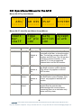
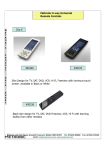
eyeheight
AF-2
AFD decoder
user manual
Table of Contents
1 System Overview ...............................................................................................4
1.1
Associated Equipment for the AF-2 ........................................................5
1.1.1 Chassis Types .....................................................................................5
1.1.2 Control Surfaces ..................................................................................5
2 Installation ..........................................................................................................7
2.1
Installation of the AF-2 product ...............................................................7
2.2
Installing the AF-2 into a flexiBox............................................................7
2.3
Connecting to an AF-2 ............................................................................7
2.4
Connecting Panels to the AF-2 ...............................................................8
3 Operation .........................................................................................................10
3.1
Manual control of the AF-2....................................................................10
3.2
Automation Control of the AF-2.............................................................10
3.3
Operational Menus for the AF-2............................................................11
4 Technical Appendix ..........................................................................................18
4.1
Technical Specification for the AF-2 .....................................................18
4.2
Technical Specification for the GPI/Tally connector..............................18
4.3
Jumpering the I-BUS (CAN-BUS) Termination .....................................18
4.4
CHP-100 SDI-TC-GPI Card ..................................................................19
-2eyeheight Unit 34 Park House Watford Business Park Greenhill Crescent Watford Herts GB WD18 8PH
Reg. No. 2855535 Telephone: +44 (0) 1923 256 000 Fax: +44 (0) 1923 256 100 email: [email protected]
Table of Figures
Figure 1 The AF-2 AFD decoder module. .............................................................4
Figure 2 Typical AF-2 on-screen displays .............................................................5
Figure 3 FlexiBox with flexiPanel fitted..................................................................5
Figure 4 Desktop modular panel FP-10.................................................................6
Figure 5 IRU panel FP-9 .......................................................................................6
Figure 6 miniBox integrated panel.........................................................................6
Figure 7 AF-2 Connections ...................................................................................8
Figure 9 I-Bus connection from chassis to panel...................................................9
Figure 10 Location Of I-Bus Termination Link .....................................................19
Figure 8 Diagram of GPI Jumpers.......................................................................19
-3eyeheight Unit 34 Park House Watford Business Park Greenhill Crescent Watford Herts GB WD18 8PH
Reg. No. 2855535 Telephone: +44 (0) 1923 256 000 Fax: +44 (0) 1923 256 100 email: [email protected]
1 System Overview
This manual describes the function of the AF-2. The AF-2 is a unit that will
decode the AFD and AR numbers, translate then into user defined text and
display both onto an overlaid screen. It will set appropriate alarm outputs in userdefined conditions.
The main features are as follows:•
The user can define a 6 digit channel Ident, definable in foreground colour,
background colour, flashing or normal mode.
•
All the AFD and error messages can be user defined, in foreground colour,
background colour, flashing or normal mode and whether that condition
triggers an alarm.
•
The main “alert” alarm can be “accepted” by the operator setting a second
“indication” alarm, which is cleared when the problem is completely
resolved.
•
The module can cope with AFDs in the range 0-7 or 8-15.
•
The module broadcasts information compatible with the MD-2 Master
Display module, enabling collation of any unit’s displays and allowing for
remote supervision.
•
The module displays suitable “Edge of picture” and “Safe action” cursors
overlaid onto the video picture.
Figure 1 The AF-2 AFD decoder module.
-4eyeheight Unit 34 Park House Watford Business Park Greenhill Crescent Watford Herts GB WD18 8PH
Reg. No. 2855535 Telephone: +44 (0) 1923 256 000 Fax: +44 (0) 1923 256 100 email: [email protected]
Figure 2 Typical AF-2 on-screen displays
1.1
Associated Equipment for the AF-2
The AF-2 is a module and requires both a chassis and a control surface to
function.
1.1.1 Chassis Types
•
flexiBox is a 1RU chassis. The order code is FB-9. This will hold a
maximum of six AF-2 modules with “Hot Swap” redundant PSU option and
“Hot Swap” AF-2 modules.
•
maxiBox is an alternative low cost 1RU chassis. The order code is MX-9.
This also will hold a maximum of six AF-2 modules but it has no redundant
PSU option and the AF units must be factory fitted.
•
miniBox is a half width 1RU high desktop unit capable of holding a single
AF-2 unit which must be factory installed. The miniBox includes a control
surface allowing recall of up to 8 predefined memories which are either
factory configured or set up by the user using an FP-9 or FP-10 connected
to the miniBox as a remote panel.
Figure 3 FlexiBox w ith flexiPanel fitted
1.1.2 Control Surfaces
•
flexiPanel is a IRU control surface that fits on the Front of a 1RU flexiBox.
The order code is FP-9. A FlexiPanel can also be used in conjunction with
a miniBox, in this case the extra accessory (Order code RR-9) will be
required
•
FP-10 is a desk mounting control surface (Order code FP-10). This unit is
a modular unit which can be used in conjunction with the units below.
-5-
eyeheight Unit 34 Park House Watford Business Park Greenhill Crescent Watford Herts GB WD18 8PH
Reg. No. 2855535 Telephone: +44 (0) 1923 256 000 Fax: +44 (0) 1923 256 100 email: [email protected]
Figure 4 Desktop modular panel FP-10
Figure 5 IRU panel FP-9
Figure 6 miniBox integrated panel
-6eyeheight Unit 34 Park House Watford Business Park Greenhill Crescent Watford Herts GB WD18 8PH
Reg. No. 2855535 Telephone: +44 (0) 1923 256 000 Fax: +44 (0) 1923 256 100 email: [email protected]
2 Installation
2.1 Installation of the AF-2 product
If this unit is already pre-installed in a flexiBox (FB-9), a maxiBox or a miniBox,
with either a local or a remote panel from the factory then refer to the "Hardware
Installation Guide" which will be enclosed with the system. If this unit is preinstalled in a miniBox (MB-9), then also refer to the "Hardware Installation Guide"
which will be enclosed with the system
If this unit has been ordered separately, we assume here that you already have a
flexiBox system with a Flexipanel and that the flexiBox has at least one spare slot
for an AF-2 card.
2.2 Installing the AF-2 into a flexiBox
To install the AF-2 into a flexiBox it is desirable (but not necessary) to power
down the flexiBox. Follow these instructions.
On the rear of the flexiBox are 6 slots for Products. Remove any spare blanking
plate. There are 2 off M2.5 Screws, which require unfastening for each blanking
plate.
Slide the Product PCB into the spare slot and firmly push it "home".
Use the four thumbscrews to fasten the unit in place.
Now refer to the "GeNETics User Guide". If your system consists of a single
flexiBox with a single flexiPanel then refer to the section titled "flexiPanel Auto
Set-up". If your system is part of a network with more than one flexiPanel then
refer to the section titled "flexiPanel Manual Set-up". This will guide you through
acquiring your product as a device on the flexiPanel.
2.3 Connecting to an AF-2
Connections for the AF-2 are shown below.
-7eyeheight Unit 34 Park House Watford Business Park Greenhill Crescent Watford Herts GB WD18 8PH
Reg. No. 2855535 Telephone: +44 (0) 1923 256 000 Fax: +44 (0) 1923 256 100 email: [email protected]
Figure 7 AF-2 Connections
See section 4 – Technical Appendix for pin-out and jumper details.
2.4 Connecting Panels to the AF-2
The AF-2 may be operated using a FP-9 Flexipanel locally mounted. For a more
operational environment the AF-2 may be supplied with a desk mounting FP-10
or remotely sited FP-9. For detailed information on connecting remote panels
refer to the section “Connection of Remote Panels to a flexiBox” in the geNETics
Hardware Installation Guide.
Below is shown a typical system consisting of an geNETics processor card in a
flexiBox controlled by a remotely mounted FP-9.
-8eyeheight Unit 34 Park House Watford Business Park Greenhill Crescent Watford Herts GB WD18 8PH
Reg. No. 2855535 Telephone: +44 (0) 1923 256 000 Fax: +44 (0) 1923 256 100 email: [email protected]
**
Connect Pins 1,2,4,7,9 from chassis to
panels (1:1). Use twisted pair AES
Digital Audio cable for pins 2 and 7. Pins
1,4,9 carry power 0.5 Amp, 13V. Use
cable with a least a 1 amp rating for pins
1,4,9. Cable llength should not exceed
250m.
**
I-Bus pins 2 & 7
** The I-BUS Network requires terminating with 100 Ohms at each extreme end of the network. Ensure that this is
done either by an external 100 ohm resistor OR ONE Panel/Product at each end has the termination set. See the
"Genetics User Guide" Under the sections "Flexipanel Power/I-BUS Jumpers".For the 4RU Panels see “4RU
Panel (FP-10) Jumpers for I-BUS” and “4RU Panel (VP-10, SW-10, AP-10) Jumpers for I-BUS” . Alternatively The
termination can be set on a Product (ie the AD-2/AD-2E module). Information about this is given in this manual.
Figure 8 I-Bus connection from chassis to panel
N.B. From 1/10/02 Eyeheight introduced a change in the flexiBox Chassis. Most
versions now have two 9 way connectors on the rear labelled “I-Bus” and “DBus”. The “I-Bus” connector is the same as the previously labelled “Can-B”
connector. Although a maxiBox is shown in this diagram the same arrangement
applies for a flexiBox chassis.
-9eyeheight Unit 34 Park House Watford Business Park Greenhill Crescent Watford Herts GB WD18 8PH
Reg. No. 2855535 Telephone: +44 (0) 1923 256 000 Fax: +44 (0) 1923 256 100 email: [email protected]
3 Operation
3.1 Manual control of the AF-2
Manual Control of the AF-2 is done using one or more of the following control
surfaces:
•
The 1RU FP-9 flexiPanel.
•
The FP10 Desk mounting panel
The FP-9 and the FP-10 have identical manual control systems. (The FP-10 is
simply a desktop version of the FP-9).
The AF-2 is, as are all genetics modules, controlled using a set of MENUS. Each
of these menus contains up to 3 parameters that are adjusted using the rotary
digipots. The Menus define all of the adjustable operational parameters in the AF2. Pressing the rotary digipots brings the parameter to its default value. Device
selection is done using the device select switches which, when pressed, will offer
the name of the device in the LCD Window. Modules can be acquired and then
de-acquired using the set-up switch. For a full description of the operation
philosophy of the geNETics system refer to the “geNETics User Guide” (section
“Operation of the flexiPanel”)
A full list of the Menus and their functions are given in section 3 of this chapter.
3.2 Automation Control of the AF-2
Automation of the geNETics products is achieved via an RS422 port.** This port
is marked RS422 on the rear of a flexiBox. For the port to work a flexiPanel
MUST be connected locally on the front of the flexiBox.
Automation control of the AF-2 can be done using the geNETics automation
protocol.
Genetics protocol is described in detail in the “GeNETics User Guide” section
titled “Automation Protocol on the geNETics Platform”. The menu list in section 3
of this chapter contains the data information for the protocol.
**On most flexiBoxes later than 1/10/02 the RS422 port has been replaced by a
“D-Bus” Port. The D-Bus port is for High Speed data transfer and is not used for
serial control. In order to achieve serial control of any products on an I-Bus
network Eyeheight Ltd have developed a RS232ÆI-bus converter “dongle”, (DG9) which enables greater flexibility of products on the I-Bus network whilst using
the same protocols as the RS422 port. Please refer to the “User guide for the
DG-9 eyeheight dongle and set-up software.
- 10 eyeheight Unit 34 Park House Watford Business Park Greenhill Crescent Watford Herts GB WD18 8PH
Reg. No. 2855535 Telephone: +44 (0) 1923 256 000 Fax: +44 (0) 1923 256 100 email: [email protected]
3.3 Operational Menus for the AF-2
Menus 00-03 Top Level Menus
-----AFD/
------
-----AR DIS
------
-----PLAY
------
-----SYSTEM
------
Menus 04-07, Ident Bar and Alarm Accept Menus
Ident
Bar
=Half
Menu Num.
4
Edge
of pic
=On
Heading
Automation
Ident Bar
Off,Half,On
Default is
Half
5
Edge of
pic
Off, On
Safe
Action
Accept
Alarm
Function
Pressing this will clear the Ident Bar,
just draw a Half bar, or draw the entire
bar. The half bar consists of the AFD
number and AFD text. The full bar also
includes a product identifier, in this
case AF-2, a user programmed
channel Ident and the AR number.
Pressing this button toggles whether
the Safe Action cursor is drawn. This
cursor only applies in defined AFD
modes.
Off,On
Default is
On
7
Accept
alarm
Pressing this button toggles whether
the Edge of picture cursor is drawn.
This cursor only applies in defined
AFD modes.
Default is
On
6
Safe
Action
=On
none
Pressing this button informs the
system that the operator has
acknowledged the current alarms,
converting them to an indication only
alarm until they clear.
- 11 eyeheight Unit 34 Park House Watford Business Park Greenhill Crescent Watford Herts GB WD18 8PH
Reg. No. 2855535 Telephone: +44 (0) 1923 256 000 Fax: +44 (0) 1923 256 100 email: [email protected]
Menus 08-11 Info Bar Menus
Ident
Fader
=75%
Menu Num.
8
ID Txt
Size
=0
Heading
Automation
Ident
Fader
0-100%
ID Bar ID Bar
H posn V posn
=100
=65
Function
The Fade level of the Overlaid Ident Bar
Default is
75%
9
10
ID Txt
0,1
Size
Default is 0
ID Bar
H posn
0-999
This set the size of the font used in the
Ident bar. 0 is the smallest and less
obtrusive.
Adjusts the horizontal position of the Ident
bar on the screen.
Default is
100
11
ID Bar
V posn
Adjusted the vertical position of the Ident
bar on the screen.
0-999
Default is
65
Menus 12-15 Ident bar size and position
A.F.D.
Range
=8-15
12
A.F.D.
range
Edit 0
Test-3
25N
0-7,8-15
Dynamc
Thresh
=On
Cage
Dark
=100
The range of the A.F.D. number
- 12 eyeheight Unit 34 Park House Watford Business Park Greenhill Crescent Watford Herts GB WD18 8PH
Reg. No. 2855535 Telephone: +44 (0) 1923 256 000 Fax: +44 (0) 1923 256 100 email: [email protected]
Default is 8-15
13
EDIT
none
Pressing the return key switches the
system into an editing mode. The
memory to be edited is displayed on
the top line this can be adjusted by
pressing the display button or by
turning the associated knob. The first 6
characters form the text of the
message, the next two digits define the
foreground and background colours.
The last digit defines whether the text
is flashing (F) or normal (N), the default
is normal so the ‘N’ may be omitted.
The colours are defined as : 0=white,
1=cyan, 2=yellow, 3=green,
4=magenta, 5=blue, 6=red and
7=black. Defining either colour to be
red, 6, will cause an alarm to be
generated when that A.F.D. message
or error message occurs. This does not
apply to the channel ID. The memory
locations are defined as : 0=ID, 18=A.F.D. 0 or 8 – 7 or 15, 9=No A.F.D
message and 10=No video message.
When editing of a message is
complete pressing return will revert the
system into normal mode.
14
Dynamc
Off, On
Thresh
Default is Off
This selects whether the cursors are
displayed in white, or switch to black at
a defined level to enhance visibility.
Cage
0-999
Dark
Default is
15
If the dynamic threshold is on, this
selects threshold where the cursors
change from white to black.
100
- 13 eyeheight Unit 34 Park House Watford Business Park Greenhill Crescent Watford Herts GB WD18 8PH
Reg. No. 2855535 Telephone: +44 (0) 1923 256 000 Fax: +44 (0) 1923 256 100 email: [email protected]
Menus 16-19 Audio bar graph size and position
No Vid
Detect
=2
Menu Num.
16
17
MD-9
System
=NO
Heading
No Vid
Automation
0-250
Detect
Default is 2
MD-9
System
0 or 1
0=off
1=on
Default 0
Function
This is the number of fields that have
to be missing before a “No Video”
alarm is triggered. Once an alarm is
triggered it is latched until accepted by
the user.
Enables status broadcasts for systems
incorporating an MD-9 Master Display
system
Menu 20-23: Memory Recall
------ ------ ------ ----------- ------ ------ -----(Mem1) (Mem2) (Mem3) (Mem4)
Menu Num.
20
Heading
MEM1
21
MEM 2
22
MEM 3
23
MEM 4
Automation
1 recalls
memory
1 recalls
memory
1 recalls
memory
1 recalls
memory
Function
Recalls configuration memory 1
Recalls configuration memory 2
Recalls configuration memory 3
Recalls configuration memory 3
- 14 eyeheight Unit 34 Park House Watford Business Park Greenhill Crescent Watford Herts GB WD18 8PH
Reg. No. 2855535 Telephone: +44 (0) 1923 256 000 Fax: +44 (0) 1923 256 100 email: [email protected]
Menu 24-27: Memory Save
Save
Mem.
#2
Save
Mem.
#1
Menu Num.
24
25
26
27
Heading
SAVE
MEM1
SAVE
MEM2
SAVE
MEM3
SAVE
MEM4
Save
Mem.
#3
Automation
1 saves
configuration
1 saves
configuration
1 saves
configuration
1 saves
configuration
Save
Mem.
#4
Function
Saves current configuration as
memory 1
Saves current configuration as
memory 2
Saves current configuration as
memory 3
Saves current configuration as
memory 4
Menu 28-31: Duplex (second/third panel) control.
These
Menus
Pass
Menu Num.
PASS
Panel:
Contrl #1=1
=OFF
#2=2
Contrl
Else->
where
Heading
Automation
28
Info "These
menus
Pass"
None
29
Info "Control
Elsewhere"
None
30
Pass
Control
Enable
0=off
Function
This causes control to be passed
to one or two FlexiPanels on the
same I-BUS network with "panel
numbers" shown in the next red
LCD Window. When control is
passed you will see the middle and
lower lines of the LCD Display say
either "OK" or "FAIL" depending
on whether control was
1=on
- 15 eyeheight Unit 34 Park House Watford Business Park Greenhill Crescent Watford Herts GB WD18 8PH
Reg. No. 2855535 Telephone: +44 (0) 1923 256 000 Fax: +44 (0) 1923 256 100 email: [email protected]
successfully passed on to either of
the selected panels. Further
presses of this button will enable
or disable the control.
31
"Panel"
numbers to
which
control can
be passed.
This feature
is used to
pass
temporary
control over
to another
panel. Upon
passing
temporary
control over
to another
panel, that
panel will
have a
flashing
"device
button LED"
indicating
that control
is available
on this
device
button.
When this button is pressed, it
changes to "Green". The Threeline display in the window then
indicates the two options, which
can be changed by adjusting the
two rotary digipots A and B.
“A” will alter the first panel number
to which you would like to pass
control.
“B” will alter the second panel
number to which you would like to
pass control.
Digipot A
0Æ58
[0Æ58]
The panel number of any panel
can be found by a momentary
press of the set-up button.
Setting either of the above panel
numbers to "0" will stop any
control being passed.
Digipot B
0Æ58
[0Æ58]
Menu 32-35: Power On Memory
Set As Recall
Pow On Pow On
Memory Memory
Total
AF_2
Reset! 220102
K07110 Ver2.1
- 16 -
eyeheight Unit 34 Park House Watford Business Park Greenhill Crescent Watford Herts GB WD18 8PH
Reg. No. 2855535 Telephone: +44 (0) 1923 256 000 Fax: +44 (0) 1923 256 100 email: [email protected]
Menu Num.
Heading
Automation
Function
32
Save
Power On
Memory
1 to save
memory
Saves current configuration as
Power On memory.
33
Recall
Power On
Memory
1 to recall
memory
Recalls the Power On memory
configuration.
34
"Total
Reset ".
1 to cause
Total Reset
This puts all current and power on
default settings to the factory
default
35
Software
version
This displays the current software
version.
- 17 eyeheight Unit 34 Park House Watford Business Park Greenhill Crescent Watford Herts GB WD18 8PH
Reg. No. 2855535 Telephone: +44 (0) 1923 256 000 Fax: +44 (0) 1923 256 100 email: [email protected]
4 Technical Appendix
4.1 Technical Specification for the AF-2
Number of Inputs
1
Type of Inputs
270Mbit Serial Digital Video Inputs 75 Ohm
Line Length
At least 200 Meters of PSF1/3 (Typically 275 Meters)
Number of Outputs
3 Output BNC’s per Card (Configurable).
Type Of Outputs
270Mbit Serial Digital Video Outputs, 75 Ohm, 800mV
Total Number Of
BNC Connections
5, consisting of 1 Fixed Input and 3 Jumper
Configurable outputs. (One BNC not used)
SDI Output Jitter
The system will add less than 0.2UI to the input Jitter.
(This is only guaranteed on issue 2 or later cards)
Current Consumption <800mA at +5V
Size
215mm by 100mm
4.2 Technical Specification for the GPI/Tally
connector
GPI inputs
Relay closure outputs
Current Consumption
1 off, short to ground to activate for alarm accept.
2 off isolated relay closure outputs up to 1 Amp
current flow. One for each Alarm.
<300mA at +5V
4.3 Jumpering the I-BUS (CAN-BUS) Termination
The I-BUS Network is the "control system" under which all Products and Panels
are networked together. Under certain circumstances it is necessary to terminate
the network. This can be done on a Panel or a "Product". To terminate this
product, locate J6 on the AD-2 Processor Card supplied which is between U1
(The large square "chip") and the Edge connector. (This is on the half of the card
labelled "CHP-100 Spartan2 Processor"). Jumper this with a 2mm link.
- 18 eyeheight Unit 34 Park House Watford Business Park Greenhill Crescent Watford Herts GB WD18 8PH
Reg. No. 2855535 Telephone: +44 (0) 1923 256 000 Fax: +44 (0) 1923 256 100 email: [email protected]
J6
Figure 9 Location Of I-Bus Termination Link
4.4
CHP-100 SDI-TC-GPI Card
Table 1 Jumper settings for GPI-SIO card
Jumper
Function
J2
Set to the Right, SDI Jitter Filtering selection
LK1
Set to Top, Polarity selection for GPI Relay Output#1
LK2
Set to Top, Polarity selection for GPI Relay Output#2
LK3
Set to Top, Polarity selection for GPI Relay Output#3
LK4
Set to Top, Polarity selection for GPI Relay Output#4
Jumpers LK1Æ4, set the polarity of the relay output
Pin 1,3,5,7
Pin 2,4,6,8
Figure 10 Diagram of GPI Jumpers
- 19 eyeheight Unit 34 Park House Watford Business Park Greenhill Crescent Watford Herts GB WD18 8PH
Reg. No. 2855535 Telephone: +44 (0) 1923 256 000 Fax: +44 (0) 1923 256 100 email: [email protected]
Table 2 25-way female D-type pin out
Pin#
Function
1.
General Purpose Output #1a (GPO1a). Isolated Relay
closure. ALERT ALARM
2.
General Purpose Output #1b (GPO1b). Isolated Relay
closure.
3.
General Purpose Output #2a (GPO2a). Isolated Relay
closure INDICATION ALARM
4.
General Purpose Output #2b (GPO2b). Isolated Relay
closure
5.
General Purpose Output #3a (GPO3a). Isolated Relay
closure
6.
General Purpose Output #3b (GPO3b). Isolated Relay
closure
7.
General Purpose Output #4a (GPO4a). Isolated Relay
closure.
8.
General Purpose Output #4b (GPO4b). Isolated Relay
closure.
9.
General Purpose Output #5 (GPO5). Open Collector
Output (<100mA)
10.
General Purpose Output #6 (GPO6). Open Collector
Output (<100mA)
11.
General Purpose Output #7 (GPO7). Open Collector
Output (<100mA)
12.
General Purpose Output #8 (GPO8). Open Collector
Output (<100mA)
13.
General Purpose Input #1 (GPI1). Pull to Ground to
activate. ACCEPT ALARM.
14.
General Purpose Input #2 (GPI2). Pull to Ground to
activate.
15.
General Purpose Input #3 (GPI3). Pull to Ground to
activate.
- 20 eyeheight Unit 34 Park House Watford Business Park Greenhill Crescent Watford Herts GB WD18 8PH
Reg. No. 2855535 Telephone: +44 (0) 1923 256 000 Fax: +44 (0) 1923 256 100 email: [email protected]
16.
General Purpose Input #4 (GPI4). Pull to Ground to
activate.
17.
General Purpose Input #5 (GPI5). Pull to Ground to
activate.
18.
General Purpose Input #6 (GPI6). Pull to Ground to
activate.
19.
General Purpose Input #7 (GPI7). Pull to Ground to
activate.
20.
General Purpose Input #8 (GPI8). Pull to Ground to
activate.
21.
N/C
22.
N/C
23.
N/C
24.
N/C
25.
GND
- 21 eyeheight Unit 34 Park House Watford Business Park Greenhill Crescent Watford Herts GB WD18 8PH
Reg. No. 2855535 Telephone: +44 (0) 1923 256 000 Fax: +44 (0) 1923 256 100 email: [email protected]