1
YAMAHA PROGRAMMING BOX
HPB
Supplement User’s Manual
ENGLISH
E
E95-Ver. 1.04
Introduction
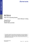
Thank you for your purchase of the YAMAHA HPB Programming Box (hereafter referred to as
"HPB"). Please read this manual supplement carefully before using the HPB, in order to ensure
correct operation.
About This Document
This document is primarily a guide to functions which have been added to the HPB. For information concerning functions not included in this document, please refer to the TPB operation explanations provided in the controller user's manual.
After reading this document, please store it in a secure location where it can be easily referenced
by the HPB operator when necessary.
Although the content of this document has been carefully checked, please contact YAMAHA
MOTOR CO., LTD. if an error, etc., is found.
For information concerning the robot unit, the controller, and other optional products, please refer
to the respective user's manuals for those items.
* Product names which appear in this document are the trademark or registered trademark names
used by the respective companies.
i
MEMO
ii
Contents
1
About the HPB
1-1
1.1
What the HPB does ................................................................................................................ 1-1
1.2
Part names and functions ....................................................................................................... 1-2
2
Connecting and Disconnecting the HPB
2.1
Connecting to, disconnecting from, the ERCD controller ...................................................... 2-1
2.1.1
2.1.2
2.2
Connecting to the ERCX controller .............................................................................................. 2-5
Disconnecting from the ERCX controller ..................................................................................... 2-8
Servo OFF when connecting and disconnecting the HPB ............................................................ 2-9
Connecting to, disconnecting from, other controllers .......................................................... 2-10
2.3.1
2.3.2
3
Connecting to the ERCD controller ............................................................................................. 2-1
Disconnecting from the ERCD controller .................................................................................... 2-4
Connecting to, disconnecting from, the ERCX controller ....................................................... 2-5
2.2.1
2.2.2
2.2.3
2.3
2-1
Connecting to the SRCX controller ............................................................................................ 2-10
Disconnecting from the SRCX controller ................................................................................... 2-13
Basic Operations
3-1
3.1
HPB control keys .................................................................................................................... 3-1
3.2
3.3
HPB and TPB key layout differences ...................................................................................... 3-3
Basic key operation ................................................................................................................ 3-4
3.4
Hierarchical menu structure .................................................................................................. 3-6
4
Using SD Memory Cards
4.1
4-1
Before using an SD memory card ........................................................................................... 4-1
4.1.1
4.1.2
4.1.3
Supported SD memory card type ................................................................................................. 4-1
Inserting and ejecting an SD memory card .................................................................................. 4-2
Loading backup data .................................................................................................................... 4-4
4.2
Saving controller data to an SD memory card ........................................................................ 4-6
4.3
4.4
Loading SD memory card data to the controller .................................................................. 4-10
Creating directories on the SD memory card ....................................................................... 4-13
4.5
4.6
Deleting files and directories from the SD memory card ..................................................... 4-16
Displaying SD memory card file content .............................................................................. 4-18
5
Error and Alarm
5.1
6
HPB error message list ........................................................................................................... 5-2
Troubleshooting
6.1
7
6-1
Problems and corrective actions ............................................................................................ 6-1
Specifications
7.1
7.2
5-1
7-1
HPB specifications ................................................................................................................. 7-1
Dimensions ............................................................................................................................ 7-2
i
MEMO
ii
1
About the HPB
The HPB is a hand-held, pendant-type programming box which connects to the robot controller in
order to edit robot operation data and execute programs. The HPB is compatible with all controllers where the TPB was used.
Featuring an interactive user operation by hierarchical menus, the HPB operating procedures are
identical to those of the TPB, and can be easily mastered even by first-time users.
What the HPB does
The HPB can be used to perform the following operations and checks. Some of the functions
shown below, however, may not be available when using some controller models and versions. For
details, refer to the controller user's manual.
Function
Programming
and
data editing
Robot operation
TPB
HPB
●
Programming
Creates & edits the programs used to operate the robot.
●
Point data entry
Edits the point data used for robot motion.
• Manual data input
For direct point data inputs using the HPB number
keys.
●
• Teaching playback
Manually moves the robot to any desired position, and
registers that position as the point data setting.
●
• Direct teaching
Basically identical to the "teaching playback" function,
but permits the robot to be moved by hand during an
emergency stop status.
●
Trace
Moves the robot in accordance with the registered
position data (point data).
●
Return-to-origin
Returns the robot to its origin position.
●
Step operation
Performs program operation one step at a time.
●
Automatic operation
Performs automatic operation in accordance with the
program.
●
Emergency stop button
This HPB button is used to perform robot emergency
stops.
●
SERVICE mode
Used to enhance safety when working in the robot's
range of motion.
●
Data backup
Saves the controller data.
Safety functions
Data backup
functions
Description
Sets the parameters for robot operation.
Parameter setting
• Save to IC memory card
Saves the controller data to an IC memory card.
• Save to flash ROM
Saves the parameter data to a flash ROM.
• Save to SD memory card
Saves controller data to an SD memory card.
Data load
×
●
●
×
●
Loads flash ROM parameter data to the controller.
• Load from SD memory card Loads SD memory card data to the controller.
Error and alarm display
●
Loads data to the controller.
• Load from IC memory card Loads IC memory card data to the controller.
• Load from flash ROM
×
●
Displays the content of an error or malfunction.
Also displays a history of past errors and alarms.
×
●
●
Duty monitor
Display functions
Others
DIO monitor
●
System information display
1
1-
About the HPB
1.1
1
1 About the HPB
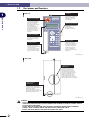
1.2
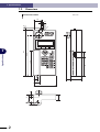
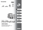
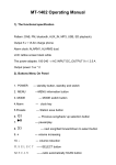
Part names and functions
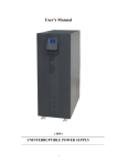
HPB unit
1
About the HPB
Emergency Stop button
Performs a robot emergency
stop when pressed during
robot operation. Release the
button lock (locks when
pressed) by turning the button
in the CW direction.
After releasing the button, a
servo recovery must be
performed from the HPB (or by
I/O operation) in order to
recover from the emergency
stop status.
Strap hole
Attaching a short strap or
necklace strap here prevents
dropping the HPB while
operating it or installing it
onto equipment.
SD memory card connector
An SD memory card can be
inserted here.
SD memory cards are
provided by the customer.
Liquid crystal display
This is a 20-character, 4-line
LCD screen. The operation
menu and other information
display here.
Connection cable
Connects the HPB to the
controller. A D-Sub 9-pin
connector (male) is provided at
one end of the cable.
To connect to controller types
other than the ERCD, use the
accessory connector adapter.
Operation keys
These keys are used to
operate the robot and to
enter programs and data, etc.
The keys are divided into 2
main groups: function keys
and data entry/operation
keys. (For operation key
details, see Chapter 3 "Basic
Operations".)
Fig. HPB-E001-001
Rear view
3-Position enable switch
(HPB-D only)
This switch is effective for use
with an external safety circuit.
This switch opens (cuts off) the
circuit when pressed or released.
Pressing it to mid-position connects
the circuit. Use this switch as the
enable switch in Service mode,
so that the external safety circuit
triggers emergency stop on the robot
when this switch is pressed or released.
Safety connector
(HPB-D only)
Use this connector with the
emergency stop or enable switch
to configure an external safety circuit.
Attaching the supplied
15-pin D-sub connector (female)
directly to this safety connector enables
the emergency stop button only.
Fig. HPB-E021-001
w
1-
2
WARNING
• THE FLUID (LIQUID CRYSTAL) IN THE LCD DISPLAY MODULE IS A HAZARDOUS SUBSTANCE. IF THIS
FLUID LEAKS FROM THE DISPLAY DUE TO DAMAGE AND ADHERES TO SKIN OR CLOTHES, WASH IT
OFF WITH SOAP AND WATER.
• DO NOT WIND THE CONNECTION CABLE AROUND THE HPB BODY WHEN STORING OR BEND IT
SHARPLY SINCE THIS MIGHT BREAK THE WIRES IN THE CONNECTION CABLE.
• DO NOT USE AN EXTENSION CORD WITH THE CONNECTION CABLE.
1 About the HPB
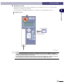
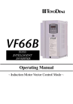
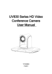
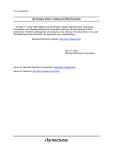
● 9-25pin conversion adapter (Accessory Item)
This adapter is required when connecting the HPB to controller types other the ERCD.
1
9-25pin conversion adapter
About the HPB
9-25pin conversion adapter
HPB connection cable
Insertion
direction
Controller side
HPB side
Signal name
Pin No.
Pin No.
Signal name
HSTCHK
RXD
TXD
+12V
GND
HSESC2
RTS
CTS
HSESC1(+24V)
SHELL
1
2
3
4
5
6
7
8
9
12
3
2
10
7
21
4
5
18
1
HSTCHK
RXD
TXD
+12V
D.G
HSESC2
RTS
CTS
HSESC1(+24V)
F.G.
SHELL
Fig. HPB-E002-001
w
WARNING
• DO NOT USE COMMERCIAL POWER SUPPLY ADAPTERS WITH THE HPB.
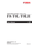
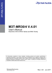
HPB-D wiring diagram
15-pin D-sub connector (female)
(If not using the HPB-D
then connect the supplied
15-pin D-sub connector (male)
to this connector.)
Safety connector
External safety circuit
(provided by customer)
Do not attempt to extend
the shorting wire between
pins 14 and 15.
1
2
3
1
2
3
4
4
5
5
6
6
7
7
8
•
•
14
15
8
•
•
14
15
Emergency stop switch
Enable switch
(deadman switch)
Controller
18
21
18
21
HPB-D
connector
EMG IN
HPB-D
HPB-D cable
Fig. HPB-E022-001
3
1-
1 About the HPB
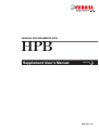
● 15-pin D-sub connectors (supplied only with HPB-D)
Use these connectors with the emergency stop or enable switch to configure an external safety
circuit.
1
About the HPB
15-pin D-sub connector (female: KS9-M532A-000)
Pin No.
1
2
・
・
・
・
・
・
・
14
15
Attaching this connector directly to the safety connector
on the HPB-D enables the emergency stop button only.
Fig. HPB-E023-001
15-pin D-sub connector (male: KS9-M532E-001)
Pin No.
1
2
3
4
・
・
・
・
・
15
If not using the HPB-D then attach this connector directly to
the 15-pin D-sub connector on the external safety circuit
so that the emergency stop circuit is shorted.
Fig. HPB-E024-001
c
1-
4
CAUTION
Set so the voltage and current ratings on the circuit connected to pins 1 to 8 on the supplied 15-pin D-sub
connector are no higher than 30V DC and 1A.
Pins 1 and 14, and pins 2 and 15 on the supplied 15-pin D-sub connector are shorted prior to shipment.
When connecting the HPB-D contacts to the external emergency stop circuit, change the wiring as shown
in the above diagram to short pins 14 and 15 together.
Never attempt to extend the shorting wire between pins 14 and 15. Doing so might cause noise in the
wiring that interferes with HPB-D or controller operation and causes faulty operation. This wiring should be
kept short.
1 About the HPB
● SD memory card
SD memory cards (required format: FAT12/16) are not available as accessory or optional items,
and must be provided by the customer.
(For SD memory card handling information, see Chapter 4 "Using SD Memory Cards".)
1
About the HPB
SD memory card
SD
MEMORY
CARD
SD memory card
Insertion direction
Fig. HPB-E003-001
c
CAUTION
• The recommended SD memory card size is "up to 32MB". Using a card size of 64MB or more during
format on Windows sometimes causes "FAT32" to appear as the preset value. However, the HPB cannot
use FAT32, so always select "FAT" at this time.
• The maximum size of the controller data file backed up on the SD memory card is "328KB". The data file
size is generally about "64KB" so up to 512 files can be stored on a 32MB memory card.
5
1-
MEMO
1-
6
2
Connecting and Disconnecting the HPB
2.1
Connecting to, disconnecting from, the ERCD controller
The HPB can be connected to, or disconnected from, an ERCD controller regardless of whether the
controller's power is ON or OFF.
2.1.1
2
CAUTION
• Do not use a modified HPB connection cable to connect the HPB to an ERCD controller, as this can result
in communication errors and equipment failure.
• An poor connection or an incorrect connector insertion can result in equipment failure and malfunctions.
Be sure that the cable is properly connected.
• An RS-232C adapter is provided as an accessory with ERCD controllers. However, this adapter is used
only for connecting a TPB to an ERCD controller, and it cannot be used to connect the HPB.
• When connecting or disconnecting the HPB connection cable from the ERCD controller, always grip the
connector body itself. When removing the connector from the ERCD controller, pull it straight out so as
not to bend the connector pins. When attaching the HPB connection cable to the ERCD controller, make
sure that both connectors are aligned with each other.
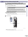
■ When ERCD controller power is OFF
1 Connect the HPB to the ERCD controller.
Plug the HPB connection cable into the PB connector on the front panel of the ERCD controller,
then tighten the screws on both sides of the connector.
HPB connection to ERCD
HPB
PB connector
Fig. HPB-E004-001
2 Turn the ERCD controller power ON.
A buzzer sounds for approximately 1 second, then the initial menu screen displays.
1
2-
Connecting and Disconnecting the HPB
c
Connecting to the ERCD controller
2 Connecting and Disconnecting the HPB
3 Verify that the initial menu screen displays.
Initial menu screen
[MENU]
select menu
2
Connecting and Disconnecting the HPB
1EDIT2OPRT3SYS 4MON
Fig. HPB-E004-003
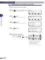
■ When ERCD controller power is ON
The HPB can be connected to the ERCD controller even when the controller power is ON.
1 Connect the HPB to the ERCD controller.
Plug the HPB connection cable into the PB connector on the front panel of the ERCD controller,
then tighten the screws on both sides of the connector. A buzzer sounds for approximately 1
second, then the initial menu screen displays.
HPB connection to ERCD
HPB
PB connector
Fig. HPB-E004-001
c
2-
2
CAUTION
• If the HPB is connected to the ERCD controller when the controller power is ON, an emergency stop and
a robot servo OFF status occur.
• If the HPB is connected to the ERCD controller while a program or I/O dedicated command is being
executed, the command execution is aborted, and robot operation is stopped.
2 Connecting and Disconnecting the HPB
2 Verify that the initial menu screen displays.
Initial menu screen
[MENU]
select menu
2
1EDIT2OPRT3SYS 4MON
3
2-
Connecting and Disconnecting the HPB
Fig. HPB-E004-003
2 Connecting and Disconnecting the HPB
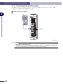
2.1.2
Disconnecting from the ERCD controller
The HPB can be disconnected regardless of whether the ERCD controller power is ON or OFF.
Disconnect the HPB from the ERCD controller.
HPB disconnection from ERCD
2
Connecting and Disconnecting the HPB
HPB
PB connector
Fig. HPB-E004-002
c
2-
4
CAUTION
• If the HPB is disconnected from the ERCD controller when the controller power is ON, an emergency stop
and a robot servo OFF status occurs.
• If the HPB is disconnected from the ERCD controller while a program or I/O dedicated command is being
executed, the command execution is aborted, and robot operation is stopped.
2 Connecting and Disconnecting the HPB
2.2
Connecting to, disconnecting from, the ERCX controller
The HPB can be connected to, or disconnected from, an ERCX controller regardless of whether the
controller's power is ON or OFF.
2.2.1
c
Connecting to the ERCX controller
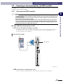
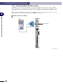
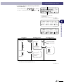
■ When ERCX controller power is OFF
1 Connect the HPB to the ERCX controller.
Attach the 9-25pin conversion adapter to the HPB connection cable, then plug the cable into
the TPB connector at the front panel of the ERCX controller. Secure by tightening the two
screws on both sides of the adapter.
HPB connection to ERCX
HPB
ERCX
PWR/
ERR
T
P
B
TPB connector
9-25pin conversion adapter
C
O
M
B
A
T
R
O
B
I
/
O
I
/
O
P
O
W
E
R
24V
N
Fig. HPB-E005-001
2 Turn the ERCX controller power ON.
A buzzer sounds for approximately 1 second, then the initial menu screen displays.
5
2-
2
Connecting and Disconnecting the HPB
CAUTION
• Do not use a modified HPB connection cable, or any relay device other than the accessory 9-25pin
conversion adapter to connect the HPB to an ERCX controller, as this can result in communication errors
and equipment failure.
• An poor connection or an incorrect connector insertion can result in equipment failure and malfunctions.
Be sure that the cable is properly connected.
• When connecting or disconnecting the HPB connection cable from the ERCX controller, always grip the
connector body itself. When removing the connector from the ERCX controller, pull it straight out so as
not to bend the connector pins. When attaching the HPB connection cable to the ERCX controller, make
sure that both connectors are aligned with each other.
2 Connecting and Disconnecting the HPB
3 Verify that the initial menu screen displays.
Initial menu screen
[MENU]
select menu
2
Connecting and Disconnecting the HPB
1EDIT2OPRT3SYS 4MON
Fig. HPB-E004-003
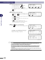
■ When ERCX controller power is ON
The HPB can be connected to the ERCX controller even when the controller power is ON.
1 Connect the HPB to the ERCX controller.
Attach the 9-25pin conversion adapter to the HPB connection cable, then plug the cable into
the TPB connector at the front panel of the ERCX controller. Secure by tightening the two
screws on both sides of the adapter. A buzzer sounds for approximately 1 second, then the
initial menu screen displays.
HPB connection to ERCX
HPB
ERCX
PWR/
ERR
T
P
B
TPB connector
9-25pin conversion adapter
C
O
M
B
A
T
R
O
B
I
/
O
I
/
O
P
O
W
E
R
24V
N
Fig. HPB-E005-001
2-
6
2 Connecting and Disconnecting the HPB
c
CAUTION
• The robot servo status may change from ON to OFF if the HPB is connected to the ERCX controller when
the controller power is ON.
• If the HPB is connected to the ERCD controller while a program or I/O dedicated command is being
executed, the command execution is aborted, and robot operation is stopped.
2
2 Verify that the initial menu screen displays.
[MENU]
select menu
1EDIT2OPRT3SYS 4MON
Fig. HPB-E004-003
7
2-
Connecting and Disconnecting the HPB
Initial menu screen
2 Connecting and Disconnecting the HPB
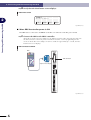
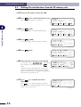
2.2.2
Disconnecting from the ERCX controller
The HPB can be disconnected regardless of whether the ERCX controller power is ON or OFF.
Robot operation is also unaffected by disconnecting the HPB. After loosening the 9-25pin conversion adapter screws, disconnect the 9-25pin conversion adapter and HPB from the ERCX controller.
When leaving the HPB disconnected from the ERCX controller for extended periods, the accessory
RS-232C dust cover should be attached to the ERCX connector area.
2
Connecting and Disconnecting the HPB
HPB disconnection from ERCX
HPB
ERCX
PWR/
ERR
T
P
B
TPB connector
9-25pin conversion adapter
C
O
M
B
A
T
R
O
B
I
/
O
I
/
O
P
O
W
E
R
24V
N
Fig. HPB-E005-002
2-
8
2 Connecting and Disconnecting the HPB
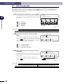
2.2.3
Servo OFF when connecting and disconnecting the HPB
Connecting the HPB
HPB connector
Fig. HPB-E006-001
With the 9-25pin conversion adapter attached to the HPB connection cable, plug the adapter in
at an angle as shown above, so that it is plugged into connector's bottom side first.
Disconnecting the HPB
HPB connector
Fig. HPB-E006-002
With the 9-25pin conversion adapter attached to the HPB connection cable, unplug the adapter
at an angle as shown above, so that it is unplugged from the connector's top side first.
c
CAUTION
Connect/disconnect the HPB carefully to avoid deforming the connector pins of the 9-25pin conversion
adapter.
9
2-
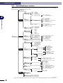
2
Connecting and Disconnecting the HPB
The SRCX, DRCX, etc. controllers have an ESC switch (used to connect and disconnect the HPB
to and from the controller) on their front panels. The ERCD and ERCX do not have this switch.
Because of this, the robot servo may turn OFF when the HPB is connected to or disconnected from
the controller. (The status LED that is lit in green changes to green/red blinking.) If this happens,
perform the servo recovery (according to the menu that automatically appears in running automatic
operation) or execute the servo recovery command (SERVO) through the I/O port. This allows the
robot to restart the normal operation.
If a problem occurs in the system when the servo is turned off, try connecting and disconnecting
the HPB as illustrated below. This will prevent the robot servo being turned OFF. Pay attention not
to deform the connector pins when connecting and disconnecting the HPB.
2 Connecting and Disconnecting the HPB
2.3
Connecting to, disconnecting from, other controllers
The HPB can be connected to, or disconnected from, a controller (SRCX, DRCX, etc.) other than
an ERCD or ERCX controller regardless of whether the controller's power is ON or OFF.
An example of the HPB connection/disconnection method versus an SRCX controller is explained
below.
2.3.1
2
Connecting and Disconnecting the HPB
c
Connecting to the SRCX controller
CAUTION
• Do not use a modified HPB connection cable, or any relay device other than the accessory 9-25pin
conversion adapter to connect the HPB to an controller, as this can result in communication errors and
equipment failure.
• An poor connection or an incorrect connector insertion can result in equipment failure and malfunctions.
Be sure that the cable is properly connected.
• When connecting or disconnecting the HPB connection cable from the robot controller, always grip the
connector body itself. When removing the connector from the robot controller, pull it straight out so as
not to bend the connector pins. When attaching the HPB connection cable to the robot controller, make
sure that both connectors are aligned with each other.
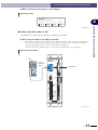
■ When controller power is OFF
1 Connect the HPB to the SRCX controller.
Attach the 9-25pin conversion adapter to the HPB connection cable, then plug the cable into
the TPB connector at the front panel of the controller. Secure by tightening the two screws on
both sides of the adapter.
HPB connection to SRCX
HPB
9-25pin
conversion
adapter
SRCX
PWR
(G)
ERR
(R)
ESC
MOTOR
TPB
U
TPB connector
V
W
COM
RGEN
N
P
L
N
ROB
I/O
ACIN1
(PWR)
I/O
NC
NC
T1
T2
100-200V/
200-230V∼
50-60Hz
MAX.1000VA
SHORT
AC100V
OPEN
AC200V
BAT
Fig. HPB-E007-001
2 Turn the controller power ON.
A buzzer sounds for approximately 1 second, then the initial menu screen displays.
10
2-
2 Connecting and Disconnecting the HPB
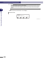
3 Verify that the initial menu screen displays.
Initial menu screen
[MENU]
select menu
2
1EDIT2OPRT3SYS 4MON
■ When controller power is ON
The HPB can be connected even while the controller power is ON.
1 Connect the HPB to the SRCX controller.
Attach the 9-25pin conversion adapter to the HPB connection cable, then plug the adapter into
the controller's TPB connector while pressing the ESC switch on the controller's front panel.
Secure by tightening the two screws on both sides of the adapter.
A buzzer sounds for approximately 1 second, then the initial menu screen displays.
HPB connection to SRCX
HPB
9-25pin
conversion
adapter
SRCX
PWR
(G)
ERR
(R)
ESC
MOTOR
TPB
U
TPB connector
V
W
COM
RGEN
N
P
L
N
ROB
I/O
ACIN1
(PWR)
I/O
NC
NC
T1
T2
100-200V/
200-230V∼
50-60Hz
MAX.1000VA
SHORT
AC100V
OPEN
AC200V
BAT
Fig. HPB-E007-001
11
2-
Connecting and Disconnecting the HPB
Fig. HPB-E004-003
2 Connecting and Disconnecting the HPB
c
2
CAUTION
• Connecting the HPB to a "power ON" status controller without pressing the ESC switch will result in an
emergency stop, and the robot servo may switch OFF.
• If the HPB is connected while a program or an I/O dedicated command is being executed, the operation
being executed will be aborted regardless of whether or not the controller's front panel ESC switch is
pressed.
Connecting and Disconnecting the HPB
2 Verify that the initial menu screen displays.
Initial menu screen
[MENU]
select menu
1EDIT2OPRT3SYS 4MON
Fig. HPB-E004-003
12
2-
2 Connecting and Disconnecting the HPB
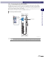
2.3.2
Disconnecting from the SRCX controller
The HPB can be disconnected regardless of whether the SRCX controller power is ON or OFF.
After loosening the 9-25pin conversion adapter screws, disconnect the 9-25pin conversion adapter
and HPB from the SRCX controller. To disconnect the HPB while a program or an I/O dedicated
command is being executed, press the ESC switch on the controller's front panel while disconnecting the 9-25pin conversion adapter and the HPB.
When leaving the HPB disconnected from the SRCX controller for extended periods, the accessory
RS-232C dust cover should be attached to the SRCX connector area.
Connecting and Disconnecting the HPB
Disconnecting the HPB from the SRCX
HPB
9-25pin
conversion
adapter
SRCX
PWR
(G)
ERR
(R)
ESC
MOTOR
TPB
U
TPB connector
V
W
COM
RGEN
N
P
L
N
ROB
I/O
ACIN1
(PWR)
I/O
NC
NC
T1
T2
100-200V/
200-230V∼
50-60Hz
MAX.1000VA
SHORT
AC100V
OPEN
AC200V
BAT
Fig. HPB-E007-002
c
2
CAUTION
If a program or I/O dedicated command is in progress, disconnecting the HPB without pressing the ESC
switch at the controller's front panel will result in an emergency stop, and the robot servo may switch OFF.
13
2-
MEMO
14
2-
3
Basic Operations
3.1
HPB control keys
The HPB control keys are divided into 2 main groups, as shown below.
HPB control key layout
3
Basic Operations
1. Function keys
2. Data entry / operation keys
Fig. HPB-E008-001
The key functions are described below.
1. Function keys
HPB Keys
∼
Description
TPB Keys
Selects modes displayed at the bottom line of the display, and executes
commands. The key numbers correspond to the mode and command
numbers.
F1 ∼ F4
2. Data entry / operation keys
HPB Keys
TPB Keys
Description
Starts robot operation in accordance with the selected program and
parameters.
RUN
Stops the robot operation which is in progress. Operation can be resumed
by pressing
again.
STOP
Selects the axis when controlling 3 or more axes. There is no CHG key on
the HPB. Instead, the following keys are provided.
Operation Description
Not available
on HPB
Switches the axis during point data
editing operations.
HPB
CHG
DIO monitor switching.
Displays the DIO monitor.
DIO
1
3-
3 Basic Operations
∼
∼
3
Numerical input keys.
0 ∼ 9
Symbol input keys.
•
Robot language input keys (used the robot language editing screen in the
program editing mode).
Basic Operations
Moves the robot in the plus and minus directions within an X, Y, Z, R
coordinate system.
For screen left/right scrolling, and cursor left/right movement.
For scrolling through displayed parameter and point numbers.
Returns to the previous mode or screen.
(BackSpace) Moves the editing cursor one space back at numerical input
operations, and erases that entry.
Registers an entered value.
3-
2
–
TIMR ∼ MOVF
X–
Z
X+
Z
Y
R–
Y
R+
X–
Z
X+
Z
STEP
UP
STEP
DOWN
ESC
BS
3 Basic Operations
3.2
HPB and TPB key layout differences
The main differences between the HPB and TPB key layout and key functions are shown below.
HPB and TPB key layout differences
No CHG key on HPB
3
EMG
TPB
Basic Operations
F1 F2 F3 F4
CHG
ESC
DIO
RUN
STOP
7
8P
9L
X
Z
5
6DO
Y R
Y +
R
3
STEP
UP
STEP
DOWN
TIMR
4
CALL
1
JMP
0
MOVA
WAIT
2
JMPB
•
MOVI
JMPF
BS
-
X
Z
+
Cursor keys
• The HPB has dedicated cursor
keys.
•
STEP
STEP
UP and DOWN keys are cursor
P/DOWN keys on the HPB.
UP/DOWN
_
MOVF
JOG key
• The HPB has JOG keys for each axis.
Fig. HPB-E009-001
c
CAUTION
The JOG key plus/minus direction layout on the HPB is the reverse of that on the TPB. Use care to avoid
specifying the wrong direction.
3
3-
3 Basic Operations
3.3
Basic key operation
HPB operations are selected from a hierarchical menu system. To display a menu item, press the
corresponding function key. The number keys and the
key are used to enter numerical values.
The following steps describe a basic HPB operation, showing how to select a robot operation
program from the initial menu.
1 Verify that the initial menu screen displays.
The initial menu screen has a [MENU] title at the top
line, with the 4 modes displayed for selection on the
bottom line.
Basic Operations
3
1EDIT
2OPRT
3SYS
4MON
(Editing)
(Operation)
(System)
(Monitor)
[MENU]
select menu
1EDIT2OPRT3SYS 4MON
Selectable menus (modes) and corresponding
function keys
Fig. HPB-E010-001
n
NOTE
The numbers to the left of each mode correspond to the function key numbers.
2 Press the function key for the desired
mode.
The screen then changes to that of the selected
mode. In the example shown at right, the initial menu
screen's
(OPRT) key was pressed to select the
OPRT (operation) mode. The following 3 sub-modes
can be selected from the OPRT mode.
Current mode
[OPRT]
select menu
1ORG 2STEP3AUTO
Fig. HPB-E010-002
1ORG (Return-to-origin)
2STEP (Step operation)
3AUTO (Automatic operation)
3 Press a function key to select the desired
sub-mode.
Each time a function key is pressed to select a menu,
processing moves further down into the hierarchical
menu system.
In the example shown at right, the OPRT mode
screen's
(STEP) key was pressed to select the
STEP mode.
Current mode
[STEP] 100% 0: 0
001:MOVA 254,100
[ 0.00]
1SPD 2RSET3CHG 4next
The
key can then be pressed to display
the next set of menu items.
Fig. HPB-E010-003
n
3-
4
NOTE
The [4 next] item displays at the right end of the bottom line when there are 5 or more selectable menu items. The
can then be pressed to display the next set of menu items. Press
to return to the previous set of menu items.
key
3 Basic Operations
4 Use the same procedure to select the next
mode.
In the example shown at right, the STEP mode
screen's
(CHG) key was pressed to select the
program changing mode. The desired value can then
be entered at the cursor ( _ ) position.
Input enabled at cursor position
[STEP] 100% 0: 0
PGM No = _
~ 99
(program No) 0
Indicates the input range.
Fig. HPB-E010-004
3
5 Enter the desired program No.
n
NOTE
Press the
Basic Operations
Use the number keys to enter the desired program
No., then press the key to select that program.
key to return to the previous screen, or to return to the next higher hierarchy level.
5
3-
3 Basic Operations
3.4
Hierarchical menu structure
HPB operations are performed by making selections from a hierarchical menu system. The HPB
menu hierarchy structure is shown below.
INFORMATION
(System information)
PGM
(Program edit)
MOD
INS
DEL
CHG
(Step edit)
(Step insert)
(Step delete)
(Program change)
MDI
(Manual data input)
CHG
PLT
3
Basic Operations
EDIT
(Editing)
PNT
(Point edit)
CHG (Point change)
SPD (Speed change)
S_SET (Speed set)
DO
(General-purpose output control)
TRC (Point trace)
PLT (Pallet No. switching)
TCH
(Teaching playback)
DTCH (Direct teaching)
DEL (Delete)
Power ON
(Initial menu screen)
OPRT
(Operation)
UTL
(Utility)
COPY (Program copy)
DEL (Program delete)
LIST (Program list)
ORG
(Return-to-origin)
ALL
X
Y
Z
R
(All axes)
(X-axis)
(Y-axis)
(Z-axis)
(R-axis)
STEP
(Step run)
SPD
RSET
CHG
VAL
S_ON
CHGT
MIO
(Speed setting)
(Program reset)
(Program change)
(Variable monitor)
(Servo ON)
(Task change)
(Memory IO monitor)
COM
X
Y
Z
R
PRM1
PRM2
(Common parameters)
(X-axis parameters)
(Y-axis parameters)
(Z-axis parameters)
(R-axis parameters)
(No.0 to 63)
(No.64 onward)
AUTO
(Auto run)
PRM
(Parameter setting)
CHG
DO
BRK
PLT
(Point change)
(General-purpose output control)
(Brake)
(Pallet No. switching)
SPD
RSET
CHG
VAL
S_ON
CHGT
MIO
(Execution speed change)
(Program reseet)
(Program change)
(Variable monitor)
(Servo ON)
(Task change)
(Memory IO monitor)
SAVE (Save)
SYS
(System)
B.UP
(Backup)
CARD
(Memory card)
LOAD (Load)
LIST
FROM
(Flash ROM)
INIT
(Initialization)
ALL
SAFE
(Safety setting)
OPT
(Option)
UTL
(Utility)
MON
(Monitor)
(List)
SAVE (Save)
LOAD (Load)
INIT
(Initialization)
PGM (Program)
PNT (Point)
PRM (Parameter)
(All data)
ACLV (Access level)
SVCE (SERVICE mode)
(Point change)
(Pallet No. switching)
XY
FLIP
XY
FLIP
ALL (All data)
ALM (Alarm history)
ERR (Error history)
PGM (Program)
PNT (Point)
PRM (Parameter)
ALL (All data)
MKDIR(Directory creation)
DEL (Delete)
VIEW (Content display)
ALOD (Automatic load)
(4-axes / 3-axes / 2 axes)
(Single-axis 4 units / 3 units / 2 units)
(4-axes / 3-axes / 2 axes)
(Single-axis 4 units / 3 units / 2 units)
EDIT
OPRT
SYS
CARD
SET
DEV
SPD
RUN
HtoR
HDPR (Hidden parameter display)
ALM
REC (Record)
ERR
(Editing)
(Operation)
(System)
(Memory card)
(Enable/Disable setting)
(Limitation to operating device)
(Speed limitation)
(Step Run/Auto run limitation)
(Hold-to-Run setting)
(Alarm)
(Error)
DIO
(DIO monitor)
DUTY
(DUTY monitor)
RUN (Monitor start)
STOP (Monitor stop)
RSLT (Result display)
Fig. HPB-E011-001
* The menu hierarchy structure varies according to the controller model and version being used.
3-
6
4
Using SD Memory Cards
SD memory cards can be used at the HPB to back up controller data.
4.1
Before using an SD memory card
4.1.1
Supported SD memory card type
Only SD memory cards with a "FAT12/16" format can be used. These cards are provided by the
customer.
The HPB does not offer the following functions with regard SD memory cards:
• Volume label display & setting function
• Attribute change function
• Format function
4
c
CAUTION
• The recommended SD memory card size is "up to 32MB". Using a card size of 64MB or more during
format on Windows sometimes causes "FAT32" to appear as the preset value. However, the HPB cannot
use FAT32, so always select "FAT" at this time.
• The maximum size of the controller data file backed up on the SD memory card is "328KB". The data file
size is generally about "64KB" so up to 512 files can be stored on a 32MB memory card.
1
4-
Using SD Memory Cards
A personal computer must be used to format an SD memory card, and for changing attributes.
4 Using SD Memory Cards
4.1.2
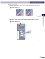
Inserting and ejecting an SD memory card
A PUSH-PUSH type (with breakage prevention mechanism for excessive-force ejection) is used for
SD memory card insertion and ejection.
■ Inserting the card
1 Insert the SD memory card into the SD memory card slot (connector).
Inserting the SD memory card (1)
Using SD Memory Cards
4
SD
MEMORY
CARD
SD memory card
Insertion direction
Fig. HPB-E012-001
2 Push the SD memory card in until a clicking sound is heard, then release it.
Inserting the SD memory card (2)
Fig. HPB-E012-002
Fig. HPB-E012-003
c
4-
2
CAUTION
• Use care to avoid inserting the SD memory card in a reversed posture.
4 Using SD Memory Cards
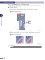
■ Ejecting the card
1 Push the SD memory card in until a clicking sound is heard, then release it.
SD memory card ejection (1)
4
2 Remove the SD memory card from the SD memory card slot (connector).
SD memory card ejection (2)
SD
MEMORY
CARD
SD memory card
Ejection direction
Fig. HPB-E012-004
3
4-
Using SD Memory Cards
Fig. HPB-E012-003
Fig. HPB-E012-002
4 Using SD Memory Cards
4.1.3
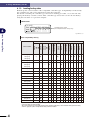
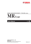
Loading backup data
Backed up data can be loaded to other compatible controller types. Compatibility is indicated by
the controller type and version information on the file's first line.
For details concerning the controller type and version checking procedure, see section 4.6 "Displaying SD memory card file content". This controller type and version can also be checked by
using the text editor on a personal computer.
VIEW screen
[VIEW] 0
000:S R C [ 1 3 . 6
008:0 ] * * P R M 0
1HEX2ASCII
4
Controller type & version
(this example indicates "SRC[13.60]".
Using SD Memory Cards
Fig. HPB-E013-001
Data compatibility table (1)
SRCD
ERCD
SR1-X
SR1-P
▲
▲
▲
▲
▲
▲
▲
○
▲
▲
▲
▲
▲
▲
▲
▲
▲
▲
▲
DRCX
▲
SRCX
ERCX
SRCP
TRCX 4 axes
TRCX 3 axes
TRCX 2 axes
TRCH 4 axes
TRCH 3 axes
SRCH
○
DRCH
SRCA
SRC
ERC
File's 1st line
DRCA
DRC-R
DRC
Controller type
SRC[1.nn]
SRC[2.nn]
SRC[4.nn]
SRC[3.nn]
DRC[5.nn]
DRC[6.nn]
○
▲
▲
▲
○
▲
DRC[7.nn]
DRC[8.nn]
TRC3[9.nn]
○
TRC4[9.nn]
SRC[13.nn]
▲
○
▲
▲
○
▲
DRC[18.nn]
▲
▲
○
○
TRC2[19.nn]
▲
TRC3[19.nn]
○
▲
TRC4[19.nn]
○
SRC[24.nn]
▲
▲
▲
○
▲
▲
▲
▲
SRC[24.nnB]
▲
▲
▲
▲
○
▲
▲
▲
SRC[33.nn]
▲
▲
▲
▲
▲
○
▲
▲
SRC[53.nn]
▲
▲
▲
▲
▲
▲
○
▲
SRC[54.nn]
▲
▲
▲
▲
▲
▲
▲
○
Other
"○" marks indicate that PGM (program data), PNT (point data), PRM (parameter data), ALL (program, point, and
parameter data) can all be loaded.
"▲" marks indicate that only PGM (program data) and PNT (point data) can be loaded. PRM (parameter data)
and ALL (program, point, and parameter data) cannot be loaded.
4-
4
4 Using SD Memory Cards
[Ex] When "SRC[24.60]" is indicated at the file's 1st line:
↓
PGM (program data), PNT (point data), PRM (parameter data), ALL (program, point, and parameter data) can all be loaded to the SRCP controller.
Only PGM (program data) and PNT (point data) can be loaded to SRC, SRCH, SRCX, SRCD,
ERCD, SR1-X, and SR1-P controllers.
[Supplemental Information]
The controller version is not indicated in newly created data (created by using the POPCOM
support software) which is loaded to a controller by way of an SD memory card, and the file types
are as shown in the table below.
Data compatibility table (2)
4
DRC
TRC4
△
△
SRCP
SRCD
ERCD
SR1-X
SR1-P
TRCX 4 axes
TRCX 3 axes
TRCX 2 axes
DRCX
△
△
△
△
△
△
△
△
TRC2
TRC3
SRCX
ERCX
TRCH 4 axes
△
TRCH 3 axes
SRCH
△
DRCH
SRCA
SRC
ERC
SRC
DRCA
DRC-R
DRC
File's 1st line
△
△
△
△
Other
"△" marks indicate that PGM (program data) and PNT (point data) can be loaded. When attempting to load PRM
(parameter data) and ALL (program, point and parameter data), a warning displays with a message requesting
loading confirmation.
[Ex] When "SRC" is indicated at the file's 1st line:
↓
PGM (program data) and PNT (point data) can be loaded to SRC, SRCH, SRCX, SRCP, SRCD,
ERCD, SR1-X, and SR1-P controllers. When attempting to load PRM (parameter data) and ALL
(program, point, and parameter data), a warning displays with a message requesting loading
confirmation.
c
CAUTION
If incorrect robot data is loaded to the robot controller, this may impair robot controller performance and
may also cause failures or malfunctions or errors, so use caution.
5
4-
Using SD Memory Cards
Controller type
4 Using SD Memory Cards
4.2
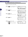
Saving controller data to an SD memory card
1 Insert an SD memory card in the HPB.
2 Press
(SYS) on the initial menu screen. [MENU]
The SYS (system) mode screen appears.
select menu
1EDIT2OPRT3SYS 4MON
Fig. HPB-E014-001
4
Using SD Memory Cards
3 Press
(B.UP).
The screen changes to the data backup mode.
[SYS]
select menu
1PRM 2B.UP3INIT4next
Fig. HPB-E014-002
4 Press
(CARD).
The screen changes to the memory card mode.
[SYS−B.UP]
select menu
1CARD2FROM
Fig. HPB-E014-003
5 Press
(SAVE).
[SYS−B.UP−CARD]
select menu
1SAVE2LOAD3LIST
Fig HPB-E014-004
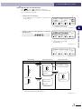
6 Specify the data to be saved.
• Press
(ALL) to save all data (program, point
and parameter data).
4-
6
• Press
(ALM) to save the alarm history.
• Press
(ERR) to save the error history.
[CARD−SAVE]
select menu
1ALL 2ALM 3ERR
Fig. HPB-E014-005
4 Using SD Memory Cards
7 Specify the save destination.
Press
(SEL) or to display the data save
destination. Data save destinations can be displayed
by the following 2 methods.
(1)
• Saving in the root directory:
* A "root directory" is the highest level directory in
the hierarchy.
[CARD−SELECT−DIR]
”SRCX .ALL” Lv1
050601 1234 4K
1SEL 2MKDIR3DEL4VIEW
(1) "Lv" indicates the directory level.
("Lv1" denotes the root directory.)
Fig. HPB-E014-006
[CARD−SELECT−DIR]
<050601 .BAK> Lv1
050601 1234
1SEL 2MKDIR3DEL4VIEW
Use the cursor keys (
) to specify
the hierarchy level where the data is to be saved.
(1)
(1) Directory names are enclosed in
angle-brackets (< >).
Fig. HPB-E014-007
[CARD−SELECT−DIR]
<.. > Lv2
1SEL 2MKDIR3DEL4VIEW
Fig. HPB-E014-008
Root directory
Sub-directory (level 2)
Sub-directory (level 3)
LV1
LV2
LV3
<050601.BAK>
<..
>
<Directory name>
<Directory name>
<..
<..
>
<Directory name>
"File name"
<Directory name>
In the above example,
this directory is specified
as the save destination.
>
<Directory name>
<Directory name>
<Directory name>
"File name"
"File name"
• Directory names are enclosed in angle-brackets (< >).
• File names are enclosed in quotation marks (" ").
Fig. HPB-E014-009
7
4-
Using SD Memory Cards
• Saving in a directory other than the root directory
(sub-directory):
4
4 Using SD Memory Cards
8 Assign the file name.
Enter a file name of up to 8 characters (alphanumeric
chars, underscore marks ( _ ), and hyphens ( - ) are
permitted), then press .
(file extension names are automatically assigned, and
need not be entered.)
The character input procedure is described below.
[Character input procedure]
Select the desired alphabetic input characters from
the character string displayed on the screen's 3rd
line. Key in numerical values and hyphens directly
from the number keys.
4
[CARD−SAVE]
= .ALL
ABCDEFGHIJKLMNOPQRST
1keyin
Using SD Memory Cards
Fig. HPB-E014-010
To select characters from the screen's 3rd line
character string, use the left/right (
) cursor
keys to move the cursor in 1-character units, or use
the up/down (
) cursor keys to move the
cursor in 10-character units.
When the cursor is positioned at the desired character, press
(keyin).
9 Assign a date to the saved file.
Use the number keys and the left/right (
)
cursor keys to enter the date (Western calendar year/
month/day) and the time (hour:minutes:seconds).
(The date and time are not entered automatically.)
After entering the date and time, press the key.
0 Press
(yes) to save the data.
To abort the data save operation, press
(no).
[CARD−SAVE]
= SRCX−1 .ALL
FGHIJKLMNOPQRSTUVWXY
1keyin
Fig. HPB-E014-011i
[CARD−SAVE]
= SRCX−1 .ALL
2005/06/01 00:00:00
Fig. HPB-E014-012
[CARD−SAVE]
save OK ?
1yes 2no
Fig. HPB-E014-013
A "saving…" message displays during the save
operation, and "save complete" displays when the
operation is completed without error.
[CARD−SAVE]
saving... 0KB
Fig. HPB-E014-014
[CARD−SAVE]
save complete
Fig. HPB-E014-015
4-
8
4 Using SD Memory Cards
c
n
CAUTION
• If an alarm occurs during the save operation, the file being written is deleted without being destroyed.
• If connection with the controller is severed during the save operation, or if the SD memory card is ejected
at that time, the file will be destroyed.
• HPB performs file management by the FAT format used on Windows personal computers. Therefore
non-contiguous file conditions occur after repeated saves and deletions, possibly reducing the file
access speed. If this occurs, back up all files to a Windows personal computer, then copy only the
required files.
NOTE
Data is saved in an ASCII format, and it can therefore be used in the POPCOM support software.
4
Using SD Memory Cards
9
4-
4 Using SD Memory Cards
4.3
Loading SD memory card data to the controller
1 Insert an SD memory card in the HPB.
2 Press
(SYS) on the initial menu screen. [MENU]
The SYS (system) mode screen appears.
select menu
1EDIT2OPRT3SYS 4MON
Fig. HPB-E015-001
4
Using SD Memory Cards
3 Press
(B.UP).
The screen changes to the data backup mode.
[SYS]
select menu
1PRM 2B.UP3INIT4next
Fig. HPB-E015-002
4 Press
(CARD).
The screen changes to the memory card mode.
[SYS−B.UP]
select menu
1CARD2FROM
Fig. HPB-E015-003
5 Press
(LOAD).
[SYS−B.UP−CARD]
select menu
1SAVE2LOAD3LIST
Fig. HPB-E015-004
6 Specify the file to be loaded.
(1)
(3)
• Specifying a file in the root directory:
Use the up/down (
) cursor keys to display
the file to be loaded, then press
(SEL) or .
[CARD−SELECT−FILE]
”SRCX .ALL” Lv1
050601 1234 4K
1SEL 2MKDIR3DEL4VIEW
(2)
(4)
(1) File names are enclosed in quotation marks (" ").
(2) Indicates the date and time (no "secs." display).
(3) "Lv" denotes the directory hierarchy level.
("Lv1" denotes the root directory.)
(4) Indicates the file size (in Kbyte units).
Fig. HPB-E015-005
10
4-
4 Using SD Memory Cards
• Specifying a directory (sub-directory) other than
the root directory:
Use the cursor keys (
(1)
[CARD−SELECT−FILE]
<050601 .BAK> Lv1
050601 1234
1SEL 2MKDIR3DEL4VIEW
) to display
(SEL) or
the file to be loaded, then press
.
(2)
(1) Directory names are enclosed in
angle-brackets (< >).
(2) Indicates the date and time (no "secs." display).
Fig. HPB-E015-006
[CARD−SELECT−FILE]
<.. > Lv2
4
1SEL 2MKDIR3DEL4VIEW
Using SD Memory Cards
Fig. HPB-E015-007
[CARD−SELECT−FILE]
”SRCX−1 .ALL” Lv2
050601 1300 4K
1SEL 2MKDIR3DEL4VIEW
Fig. HPB-E015-008i
Root directory
Sub-directory (level 2)
Sub-directory (level 3)
LV1
LV2
LV3
<050601.BAK>
<..
>
"SRCX-1.ALL"
<Directory name>
<Directory name>
<Directory name>
<..
In the above example,
this file is specified for
loading.
<..
>
"File name"
>
<Directory name>
"File name"
<Directory name>
"File name"
"File name"
• Directory names are enclosed in angle-brackets (< >).
• File names are enclosed in quotation marks (" ").
Fig. HPB-E015-009
11
4-
4 Using SD Memory Cards
7 Specify the data to be loaded.
• To load program data, press
• To load point data, press
(PGM).
(PNT).
• To load parameter data, press
(PRM).
[CARD−LOAD]
select menu
1PGM 2PNT 3PRM 4ALL
Fig. HPB-E015-010
• To load all data (program, point, parameter), press
(ALL).
8 Check the onscreen message.
• An overwrite confirmation message displays only if
(PGM) or
(PNT) was selected at Step
7.
4
[CARD−LOAD]
program data
over write ?
1yes 2no
Using SD Memory Cards
• Press
(yes) to retain program and point data
which is not redundant.
Fig. HPB-E015-011
• Press
(no) to initialize all controller data, and
then load the new data.
• If
(ALL) was selected at Step 7, the
controller's program and point data is initialized,
and a load confirmation message displays.
9 Press
Press
(yes) to load the data.
(no) to abort the data loading operation.
[CARD−LOAD]
program data
load OK ?
1yes 2no
Fig. HPB-E015-012
A "loading…" message displays while the data is
being loaded, and a "load complete" message
displays when loading is completed.
[CARD−LOAD]
loading... 78%
Fig. HPB-E015-013
[CARD−LOAD]
load complete
Fig. HPB-E015-014
c
12
4-
CAUTION
• Data loading does not occur if the initializing processing fails at Step 8. Moreover, if an error occurs
during the data loading operation, the loaded data up to the error occurrence point remains in the
controller because initializing occurs before the data loading operation.
• Do not eject the SD memory card during a data loading operation.
• HPB performs file management by the FAT format used on Windows personal computers. Therefore
non-contiguous file conditions occur after repeated saves and deletions, possibly reducing the file
access speed. If this occurs, back up all files to a Windows personal computer, then copy only the
required files.
• If incorrect robot data is loaded to the robot controller, this may impair robot controller performance and
may also cause failures or malfunctions or errors, so use caution.
4 Using SD Memory Cards
4.4
Creating directories on the SD memory card
1 Insert an SD memory card in the HPB.
2 Press
(SYS) on the initial menu screen. [MENU]
The SYS (system) mode screen appears.
select menu
1EDIT2OPRT3SYS 4MON
Fig. HPB-E016-001
3 Press
(B.UP).
[SYS]
select menu
1PRM 2B.UP3INIT4next
Fig. HPB-E016-002
4 Press
(CARD).
The screen changes to the memory card mode.
[SYS−B.UP]
select menu
1CARD2FROM
Fig. HPB-E016-003
5 Press
(LIST).
[SYS−B.UP−CARD]
select menu
1SAVE2LOAD3LIST
Fig. HPB-E016-004
6 Specify the location where the directory is
to be created.
Display the hierarchy level where the directory is to
be created, then press
(MKDIR). The procedure for displaying the hierarchy level where the
directory is to be created, is given below.
(1)
• For creation in the root directory:
* A "root directory" is the highest level directory in
the hierarchy.
* An "empty" message displays if there are no files
in the SD memory card.
[CARD−LIST]
”SRCX .ALL” Lv1
050601 1234 4K
1MKDIR2DEL3VIEW
(1) "Lv" denotes the directory hierarchy level.
("Lv1" denotes the root directory.)
Fig. HPB-E016-005
13
4-
Using SD Memory Cards
The screen changes to the data backup mode.
4
4 Using SD Memory Cards
• For creation in a directory other than the root
directory (sub-directory):
Use the cursor keys (
) to specify
the hierarchy level where the directory is to be
created.
[CARD−LIST]
<050601 .BAK> Lv1
050601 1234
1MKDIR2DEL3VIEW
Fig. HPB-E016-006
[CARD−LIST]
<.. > Lv2
1MKDIR2DEL3VIEW
Fig. HPB-E016-007
Using SD Memory Cards
4
Root directory
Sub-directory (level 2)
Sub-directory (level 3)
LV1
LV2
LV3
<050601.BAK>
<..
>
<Directory name>
<Directory name>
<..
<..
>
<Directory name>
"File name"
<Directory name>
In the above example,
a directory is being
created here.
>
<Directory name>
<Directory name>
<Directory name>
"File name"
"File name"
• Directory names are enclosed in angle-brackets (< >).
• File names are enclosed in quotation marks (" ").
Fig. HPB-E016-008
14
4-
4 Using SD Memory Cards
7 Assign a name to the directory.
Enter a directory name (alphanumeric chars, underscore marks ( _ ), and hyphens ( - ), and period ( . )
are permitted), then press .
An 8.3 input format is used (max. 8-character
directory name, and 3-character extension name).
The character input procedure is described below.
[Character input procedure]
Select the desired alphabetic input characters from
the character string displayed on the screen's 3rd
line. Key in numerical values, hyphens, and period,
directly from the number keys.
[CARD−LIST]
=
ABCDEFGHIJKLMNOPQRST
1keyin
Fig. HPB-E016-009
8 Assign a date to the directory being
created.
Use the number keys and the left/right (
)
cursor keys to enter the date (Western calendar year/
month/day) and the time (hour:minutes:seconds).
(The date and time are not entered automatically.)
After entering the date and time, press the key.
9 Press
(yes) to create the directory.
To abort the data save operation, press
(no).
If the directory creation is completed without error,
the system returns to the Step 6 screen.
[CARD−LIST]
= 050601−1.BAK
ABCDEFGHIJKLMNOPQRST
1keyin
Fig. HPB-E016-010
[CARD−LIST]
= 050601−1.BAK
2005/06/01 00:00:00
Fig. HPB-E016-011
[CARD−LIST]
create ?
1yes 2no
Fig. HPB-E016-012
c
n
CAUTION
A directory name which already exists in the same directory cannot be assigned as the name of the
directory being created.
NOTE
A directory hierarchy level down to level 8 (Lv1 to Lv8) can be selected as the directory creation level.
15
4-
Using SD Memory Cards
To select characters from the screen's 3rd line
character string, use the left/right (
) cursor
keys to move the cursor in 1-character units, or use
the up/down (
) cursor keys to move the
cursor in 10-character units.
When the cursor is positioned at the desired character, press
(keyin).
4
4 Using SD Memory Cards
4.5
Deleting files and directories from the SD memory card
1 Insert an SD memory card in the HPB.
2 Press
(SYS) on the initial menu screen. [MENU]
The SYS (system) mode screen appears.
select menu
1EDIT2OPRT3SYS 4MON
Fig. HPB-E017-001
4
Using SD Memory Cards
3 Press
(B.UP).
The screen changes to the data backup mode.
[SYS]
select menu
1PRM 2B.UP3INIT4next
Fig. HPB-E017-002
4 Press
(CARD).
The screen changes to the memory card mode.
[SYS−B.UP]
select menu
1CARD2FROM
Fig. HPB-E017-003
5 Press
(LIST).
[SYS−B.UP−CARD]
select menu
1SAVE2LOAD3LIST
Fig. HPB-E017-004
6 Select the file or directory to be deleted.
Use the cursor keys (
) to display the
file or directory to be deleted, then press
(DEL).
(A directory cannot be deleted if it contains subdirectories and files. Therefore, deletions should
always be performed in ascending order, beginning
from the lower hierarchy levels.)
7 Press
16
4-
(yes) to delete the file or
[CARD−LIST]
”SRCX−1 .ALL” Lv2
050601 1300 4K
1MKDIR2DEL3VIEW
Fig. HPB-E017-005
directory.
[CARD−LIST]
delete ?
Press
(no) to abort the deletion operation.
If the deletion is completed without error, the system
returns to the Step 6 screen.
1yes 2no
Fig. HPB-E017-006
4 Using SD Memory Cards
c
CAUTION
• A directory cannot be deleted if it contains sub-directories and files. Therefore, deletions should always
be performed in ascending order, beginning from the lower hierarchy levels.
• Although system files and hidden files can be displayed, they cannot be deleted. This applies to
read-only files, as well.
• HPB performs file management by the FAT format used on Windows personal computers. Therefore
non-contiguous file conditions occur after repeated saves and deletions, possibly reducing the file
access speed. If this occurs, back up all files to a Windows personal computer, then copy only the
required files.
4
Using SD Memory Cards
17
4-
4 Using SD Memory Cards
4.6
Displaying SD memory card file content
1 Insert an SD memory card in the HPB.
2 Press
(SYS) on the initial menu screen. [MENU]
The SYS (system) mode screen appears.
select menu
1EDIT2OPRT3SYS 4MON
Fig. HPB-E018-001
4
Using SD Memory Cards
3 Press
(B.UP).
The screen changes to the data backup mode.
[SYS]
select menu
1PRM 2B.UP3INIT4next
Fig. HPB-E018-002
4 Press
(CARD).
The screen changes to the memory card mode.
[SYS−B.UP]
select menu
1CARD2FROM
Fig. HPB-E018-003
5 Press
(LIST).
[SYS−B.UP−CARD]
select menu
1SAVE2LOAD3LIST
Fig. HPB-E018-004
6 Specify the file with the content to be
displayed.
Use the cursor keys (
file name, then press
content.
) to display the
(VIEW) to display its
(1)
[CARD−LIST]
”SRCX−1 .ALL” Lv2
050601 1300 4K
1MKDIR2DEL3VIEW
(2)
(3)
(1) File names are enclosed in quotation marks (" ").
(2) Indicates the date and time (no "secs." display).
(3) Indicates the file size (in Kbyte units).
Fig. HPB-E018-005
18
4-
4 Using SD Memory Cards
7 Display the file content.
The file content displays in ASCII code.
For a hexadecimal display, press
(HEX).
To switch from a hexadecimal display to an ASCII
display, press
(ASCII).
(1)
(2)
[VIEW] 0
000:S R C [ 1 3 . 6
008:0 ] * * P R M 0
1HEX2ASCII
[VIEW] 0
000:5352435B31332E36
008:305D0D0A50524D30
1HEX2ASCII
(1) The first character position of the displayed
character string displays in hexadecimal code.
Fig. HPB-E018-006
n
NOTE
An ASCII code display comprises 0x20 to 0x7E and 0xA1 to 0xDF, with all others displaying as asterisks (*).
19
4-
Using SD Memory Cards
(2) First character position of the displayed
character string (in the above example,
"S" is the 0 character position.)
4
MEMO
20
4-
5
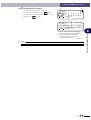
Error and Alarm
An error No. and message display on the HPB screen if an error occurs due to inappropriate operation (operator error). An alarm No. and alarm message display in the event of a system problem.
For details concerning the content of error and alarm messages, refer to the user's manual for the
controller in question.
Only error messages display (no error No.) for HPB related errors. (See section 5.1 "HPB error
message list".)
Examples of error and alarm messages which display on the HPB screen are given below.
Error message example
Error number
Error message
5
Fig. HPB-E019-001
Alarm message example
Alarm number
Alarm message
[STEP]
32:origin incomplete
Fig. HPB-E019-002
Example of HPB related error message
Error message
[CARD]
card detect...
card write protected
1SAVE2LOAD3LIST
Fig. HPB-E019-003
1
5-
Error and Alarm
[EDIT]
select menu
43:cannot find PGM
1PGM 2PNT 3UTL
5 Error and Alarm
5.1
HPB error message list
Only error messages display (no error No.) for HPB related errors. The HPB related error messages
are listed below, together with the corrective actions.
Message
SIO error
Meaning
(1) HPB was connected while a dedicated command input was ON.
(2) No response from controller.
(3) HPB is connected to an incompatible controller.
Corrective Action
(1) Turn all dedicated command inputs OFF before connecting the HPB.
(2) Reconnect the HPB, or restart the controller.
Message
card not exist
5
Meaning
No SD memory card.
Corrective Action
Insert an SD memory card into the SD memory card slot (connector).
Error and Alarm
(3) Upgrade the HPB version.
Message
card failed
Meaning
Detection of SD memory card failed.
Corrective Action
• Eject the SD memory card, re-insert it, then try the operation again.
• Perform a "chkdsk" operation from the command prompt of a Windows personal computer.
Message
card failed (FAT)
Meaning
The SD memory card format is other than FAT (12 or 16).
Corrective Action
Perform FAT formatting of the SD memory card on a Windows personal computer.
* Formats other than FAT (12 or 16) cannot be used.
Message
card full
Meaning
No space available for file creation on the SD memory card.
Corrective Action
Delete unnecessary files; use a new SD memory card; use sub-directories.
Message
card empty
Meaning
There are no files or sub-directories on the SD memory card.
Corrective Action
Use a Windows personal computer to check the card for the presence of files and sub-directories.
Message
card write protected
Meaning
The SD memory card's "write protect" switch is set to "write prohibit".
Corrective Action
Set the SD memory card's "write protect" switch to "write enable".
Message
card read error
Meaning
SD memory card reading failed.
Corrective Action
• If the SD memory card was ejected during loading (LOAD) or content display (VIEW), repeat the
operation.
• If the SD memory card was ejected during a save (SAVE), directory creation (MKDIR), or file/subdirectory deletion (DEL) operation, the file system will be destroyed. Therefore, perform a
"chkdsk/f" operation without delay from the command prompt of a Windows personal computer.
5-
2
5 Error and Alarm
Message
card write error
Meaning
SD memory card writing failed.
Corrective Action
• If the memory card became full during a save (SAVE) operation, the most recently saved file will
be incomplete. Delete this file and other unnecessary files, or insert a new SD memory card, then
repeat the save operation.
• If the memory card became full during a directory creation (MKDIR) operation, either delete
unnecessary files or insert a new SD memory card, then repeat the directory creation operation.
• If the SD memory card was ejected during a save (SAVE), directory creation (MKDIR), or file/subdirectory deletion (DEL) operation, the file system will be destroyed. Therefore, perform a
"chkdsk/f" operation without delay from the command prompt of a Windows personal computer.
Message
access denied
Meaning
The following items cannot be deleted: the sub-directories themselves (<.. >), directories which
contain data, system files/directories, hidden files/directories, read-only files/directories.
Corrective Action
• Delete all the files in a sub-directory before deleting (DEL) that sub-directory.
5
• Use a Windows personal computer to check the memory card for the presence of files and
directories, then change the "system", "hidden", or "read-only" attribute.
name already exist
Meaning
An existing file or sub-directory name was specified.
Corrective Action
Specify a different name.
Message
file empty
Meaning
The file is empty.
Corrective Action
Use another file.
Message
no data loaded
Meaning
The specified data type does not exist in the file.
Corrective Action
• Specify another file at the loading (LOAD) operation.
Error and Alarm
Message
• Specify another data type at the loading (LOAD) operation.
Message
cannot access
Meaning
An access level prohibited operation occurred.
Corrective Action
Change the access level.
3
5-
MEMO
5-
4
6
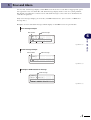
Troubleshooting
The corrective actions for HPB problems are explained in this chapter.
6.1
Problems and corrective actions
When an HPB problem occurs, take the appropriate corrective action with reference to the table
below. If the problem persists after the corrective action has been taken, contact (without delay)
our sales office or sales representative.
No.
Problem
Probable Cause
Corrective Action
A beeping sound fails to occur when 1) The 9-25pin conversion adapter
is not being used.
HPB is connected, and nothing
2) The HPB connection cable has
displays on the LCD screen.
been extended using a
commercially available
communication cable.
3) The HPB connection cable is
defective.
• Use the 9-25pin conversion
adapter.
• Connect the HPB directly to the
controller (do not use a
commercially available
communication cable).
• Replace the HPB.
• If there is an open-circuit in the
cable, contact our sales office or
representative.
2
Robot fails to stop when Emergency 1) The 9-25pin conversion adapter
is not being used.
Stop button is pressed.
2) The HPB connection cable has
been extended using a
commercially available
communication cable.
3) The HPB connection cable is
defective.
• Use the 9-25pin conversion
adapter.
• Connect the HPB directly to the
controller (do not use a
commercially available
communication cable).
• Replace the HPB.
• If there is an open-circuit in the
cable, contact our sales office or
representative.
6
Troubleshooting
1
1
6-
MEMO
6-
2
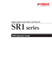
7
Specifications
7.1
HPB specifications
Item
Basic
specifications
External
inputs/outputs
General
specifications
W107 × H230 × D53mm (not including strap holder and emergency stop button)
Weight
650g
Power consumption 5V, 200mA or less
Power supply
DC 12V (supplied from controller)
Cable length
3.5m
Interface
RS-232C 1CH (dedicated for communication with controller)
Display
Monochrome LCD, 20 chars. × 4 lines
Operation keys
Membrane sheet keys
Emergency Stop
button
Normally closed contact (with lock function)
Auxiliary memory
device
SD memory card (FAT 12/16 format)
Ambient operating
temperature
0 to +40°C
Ambient storage
temperature
-10 to +65°C
Ambient operating
humidity
35 to 85% RH (no condensation)
Noise immunity
Conforms to IEC61000-4-4 level 2
Compatible controllers
Compatible with all controllers where TPB use is possible.
7
Specifications
Others
Specification
Outer dimensions
1
7-
7 Specifications
7.2
Dimensions
Dimensional outlines
Units: mm
38
φ3
0
10
φ4
.
5
9.5
95
128
Specifications
205
25
230
7
20
18.5
28
16
37
27
12
107
7-
2
53
MEMO
Revision record
Manual version
Issue date
Ver. 1.00
Ver. 1.01
Ver. 1.02
Ver. 1.03
Ver. 1.04
Jun. 2005
Oct. 2005
Feb. 2006
Jul. 2007
Oct. 2007
Description
English manual Ver. 1.00 is based on Japanese manual Ver. 1.00.
English manual Ver. 1.01 is based on Japanese manual Ver. 1.01.
English manual Ver. 1.02 is based on Japanese manual Ver. 1.02.
English manual Ver. 1.03 is based on Japanese manual Ver. 1.03.
English manual Ver. 1.04 is based on Japanese manual Ver. 1.04.
Supplement User’s Manual
Programming Box
HPB
Oct. 2007
Ver. 1.04
This manual is based on Ver. 1.04 of Japanese manual.
© YAMAHA MOTOR CO., LTD.
IM Operations
All rights reserved. No part of this publication may be reproduced in
any form without the permission of YAMAHA MOTOR CO., LTD.
Information furnished by YAMAHA in this manual is believed to be
reliable. However, no responsibility is assumed for possible
inaccuracies or omissions. If you find any part unclear in this manual,
please contact YAMAHA or YAMAHA sales representatives.