1
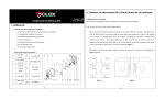
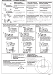
(3). To set the deadbolt as "Left Open" or "Right Open" on the Rear panel Assembly, reference Figure 3: III. Install Deadbolt Body 1. Determine the desired installation height and position of the deadbolt in relation to the door; then adhere the hole-drilling-template to the door, accordingly (see Figure 4-1 below). 2. Insert the deadbolt body into the matching hole slot (see Figure 5 below): Note: There is an "UP" symbol on the deadbolt body. Before installing the deadbolt body, make sure its positioning is consistent with the direction of the symbol. Figure 3 As shown in Figure 3, there is a "Left open/Right Open" set switch on the rear panel assembly of the deadbolt. Note the user can turn the switch to the left side (L) to set the door's opening direction as "Left Open"; or turn the switch to the right side (R) to set the door's opening direction as "Right Open". Figure 4-1 Figure 4-2 Figure 5 Set the length of the deadbolt body based on the distance from the Door Edge to the center of the circle (the opening hole distance is about 2 ½ inches ( 65 mm), as shown in Figure 4-1). The opening distance matching the Note: default length of the deadbolt body is 2 ¼ inches (60 mm). If the distance of 2 ¾ inches (70 mm) is required, reset ① Before installing the deadbolt, you must first determine the door's opening direction as either “left the length of the deadbolt body by following these steps: open” or “right open”. (1) Figure 4-2: Hold part ① of the Deadbolt Body, rotate part ② by 45°, and pull back part ②. ② According to the door's opening direction, switch the "Left/Right Open" set switch to the corresponding (2). Rotate part ② by 45° in the other direction to make the hole on part 2 match with the hole of 2 ¾ inches position (For “Left Open”, position the switch to the left side; For “Right Open” position the switch to the (70 mm) on the lock body. Note: When you shorten the length of the Lock Body, perform the following steps: right side). (1). Hold part ①, rotate part ② by 45°, and push part ② ahead. (2). Rotate part ② by 45° in the other direction to make the card pillar of the lock body be embedded into the matching card hole of 2 ¼ inches (60 mm). -3- -4-