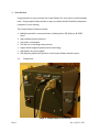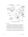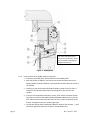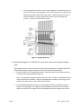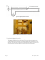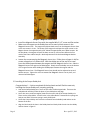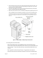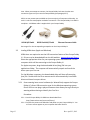
1
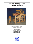
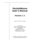
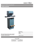
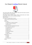
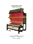
Compu-Dobby® IV For the Classic / Positive Dobby Head Installation Guide and User Manual Revision: April 23, 2012 AVL Looms, Inc. 2360 Park Avenue | Chico, CA 95928-6785 800 626-9615 | 530 893-4915 | 530 893-1372 (fax) Website: www.avlusa.com | E-mail: [email protected] © Copyright 2012 Table of Contents 1 Introduction 1.1 Components 1.2 Compatibility 1.3 Packaging 1.4 Preparation 2 Installation Instructions 2.1 Preparing the Dobby Head 2.2 Installing the Magnet 2.3 Installing the Magnetic Sensor Case 2.4 Installing the Compu-Dobby Unit 2.5 Installing Electrical and Data Cables 2.6 Adjusting the Compu-Dobby Unit 3 Use Instructions 3.1 Choosing the Communication Connection 3.2 Installing USB Drivers 3.3 Setting Ethernet IP Address 3.4 Software Connection 3.5 Resetting Communications 3.6 Maintenance 3.7 Troubleshooting Page 1 Rev. April 23, 2012 1. Introduction Congratulations on your purchase of a Compu-Dobby® for your classic or positive dobby loom. Going computerized promises to open up a whole world of flexibility and pattern complexity in your weaving. The Compu-Dobby IV features include: 1.1 Multiple methods for communications, including direct USB, Ethernet, & RS232 Serial High reliability harness selection Low power consumption The latest in circuit design and processor Highly reliable magnetic position sensor technology High quality rare earth magnet Easy adjusting pillow block system or retro Compu-Dobby I bracket system Components Image 1: Compu-Dobby IV 16H Positive Page 2 Rev. April 23, 2012 Figure 1: Compu-Dobby – Dobby Head 1.2 Compatibility The Compu-Dobby IV Positive was designed to fit all AVL 16 and 24 harness looms equipped with the classic or positive dobby, which includes all AVL mechanical dobbys. The compatible loom types are the Folding Dobby Loom (FDL), Industrial Dobby Loom (IDL), Professional Dobby Rug Loom (RL), Production Dobby Loom (PDL), Studio Dobby Loom (SDL), Technical Dobby Loom (TDL), and the A-Series Loom equipped with a classic/positive dobby head. Any weaving loom control software with a Compu-Dobby IV driver will control the Compu-Dobby IV. Contact AVL to discuss compatible software products. Page 3 Rev. April 23, 2012 For connection, the controlling computer may be of any make that is compatible with the loom control software and has a 9-pin serial, USB or Ethernet connector. The Compu-Dobby IV is a USB 2.0 device utilizing two types of USB drivers: direct USB and virtual port USB. Direct USB meets the definition of a plug and play device. As a virtual port USB device, the Compu-Dobby IV will mimic serial Com port. AVL supplies both types of USB drivers in a single package at www.avlusa.com/resources/library. These drivers are Windows XP, Vista and 7 compatible. Other operating systems may be supported. Please contact AVL for more information. The Compu-Dobby IV Ethernet connection is both static and dynamic IP compatible. Page 4 1.3 Packaging The Compu-Dobby IV is shipped in specially designed packaging to protect it while in transit. Please save the packaging in case there is need to ship the equipment. Failure to use appropriate packaging during shipment will void your warranty and you will be responsible for any damages incurred. 1.4 Preparation Installation of the Compu-Dobby is a relatively simple affair, but it does differ slightly from loom to loom, and from era to era. Therefore, we request that you review the following instructions before beginning. Before you start, you’ll want to gather a few tools: Medium Phillips screwdriver Small bladed screwdriver Scissors Pliers Crescent or 7/16” wrench Needle nose pliers Pencil Scotch or masking tape Electric drill 1/8” drill bit Rev. April 23, 2012 Open the box, find the packing list and check to be sure everything on the list is in your box. We do our best to be complete, but sometimes we’re all too human, contact us if something is missing. Got your tools? Got your parts? Let’s begin. 2. Installation Instructions 2.1 Replacing Compu-Dobby I or Compu-Dobby II Remove the old Compu-Dobby box(es), Magnet and Sensor Case and go to section 2-3 below for instructions on how to install your new Compu-Dobby IV. 2.2 Preparing the Mechanical Dobby Head The Compu-Dobby will essentially nest in the Dobby head. First, however, you’ll need to remove a few pieces to create the proper clearance. 2.2.1 Page 5 From the left side of the Dobby (see Figure 2): Remove the spring labeled #1. Remove spring #2. With the bladed screwdriver, remove the screw labeled #3. You may need a pair of needle nose pliers here to hold the body of the screw post while you loosen the screw. When you’ve removed the screw, push the post back enough that you can disengage the cable loop. Once the cable end is free, replace the screw post and screw so they don’t get lost. Remove Phillips screws that secure the cord retainer (#4) to the back of the Dobby head. With pliers, crush and remove the black caps (#5, #6). You may have a stop collar here — if so, use an Allen wrench to loosen and remove it. Remove the Detent Arm (#7). Disconnect the end of spring #8. Remove the Dobby Hook Assembly (#9) with the attached Dobby Index Lever. Rev. April 23, 2012 *On some older looms, there may be an extra pin here. Please remove it before mounting the Magnetic Sensor Case. Figure 2: Dobby Head 2.2.2 Page 6 From the front of the Dobby Head (see Figure 3): Disconnect the dobby chain and remove it from the dobby head. With the Phillips screwdriver, remove the two screws that keep each of the Dobby Cylinder Retention Brackets in place (aluminum pieces with set screws in the middle). Carefully pry out the brackets and slide the dobby cylinder free of its slots. A couple of small wooden pillow blocks and springs will come out with the cylinder. Once you've removed these brackets, use the 7/16" wrench to loosen the hex jam nuts on the face of the Dobby Cylinder Adjustment Brackets, then use the 1/8" Allen wrench to back each set screw out until it is flush to the back of the bracket. Re-tighten each hex nut until finger tight. Put the two springs and the Adjustment Brackets aside for the moment — you’ll need them again later when you install the Compu-Dobby Unit. Rev. April 23, 2012 You may again have occasion to convert your Dobby to its mechanical mode, so you’ll want to keep its parts together. Gather all the loose parts, except the two Adjustment Brackets and springs, place them in a plastic bag and store them in Compu-Dobby box. And you might want to throw in your extra pegs and wrench — you won’t need those for a while! Figure 3: Dobby Head Face 2.3 Installing the Magnet for a FDL/PDL/TDL and A-Series with the classic/positive dobby head. The magnetic sensor case contains two sensor which responds to a magnetic field. This field is produced by a magnet, which you'll need to affix to the Dobby Arm. Place the Dobby Arm in its uppermost position. Measure and drill a 1/8” diameter hole to ¾” deep at the location identified in Figure 4. Note: This measurement applies to looms built after 1997. Variation in the dobby head may require this different procedure. Align the magnet/bracket assembly as per Image 2, then mark the hole with a pencil. Drill a 1/8” hole to ¾” deep. Page 7 Install the Magnet/Bracket assembly on to the Dobby Arm with the supplied screw (see Image 2). The right edge of the magnet should be aligned with the left side of the Dobby Head. In this position, the magnet will be immediately opposite the magnetic sensor case. Rev. April 23, 2012 Figure 4: Magnet/Bracket Location Image 2: Magnet Assembly Mounted on Dobby Arm 2.4 Installing the Magnetic Sensor Case The Magnetic Dobby Arm Sensor (see Image 3) is the unit that sends signals to the Compu-Dobby and tells it whether the harnesses (dobby arm) are up or down. It has two slots. One slides over the bottom pin of Spring #1 (see Figure 2). The other slot is held in place by a screw that replaces the center brace screw of the dobby. Page 8 Rev. April 23, 2012 Image 3: Magnetic Sensor Case Install the Magnetic Sensor Case with the supplied #8 x 2 1/2" screw and flat washer. Make sure the magnet on the Dobby Arm can be seen by both sensors in the Magnetic Sensor Case. The magnet should pass both sensors on the Magnetic Sensor Case as the arm moves in its arc. The center of the magnet should pass the upper sensor in the Magnet Sensor Case approximately 1/16” below the upper dobby arm rubber bumper. On the way down, the magnet will pass the lower sensor by a fair amount before the arm reaches the lower rubber bumper. Make adjustments with the slotted Magnet Bracket Assembly. Loosen the screw securing the Magnetic Sensor Case. Fold a piece of paper in half to create a shape that is 2 sheets thick. With the dobby arm at the top of its travel insert the folded paper between the magnet and the Magnetic Sensor Case. Slide the Magnetic Sensor Case against the folded paper. Slowly move the dobby arm to the bottom of its range of motion while holding the folded paper between the magnet and the Magnetic Sensor Case. The Magnetic Sensor Case should now be adjusted at top and bottom sensors. Tighten the screw to secure the Magnetic Sensor Case in place, and remove the folded paper. 2.5 Installing of the Compu-Dobby Unit Congratulations! — You’ve completed all the hard work and will find the next task, installing the Compu-Dobby unit, instantly gratifying. Page 9 Look at the Compu-Dobby unit. You’ll see two rows of white tipped rods. These are the solenoid ends and they’ll take the place of your dobby bars and pegs. You’ll also note a small rectangular plastic block on each side of the Compu-Dobby unit. These are the pillow blocks. See the holes in the pillow blocks? Remember the springs we had you set aside? Place one spring in each pillow block. Orient the Compu-Dobby unit so that the solenoids face the Dobby head and are at the bottom of the box. Align the blocks with the slots in the Dobby head and slowly slide the unit into the Dobby head as shown in Figure 5. Rev. April 23, 2012 At the end of each slot, you’ll see a hole. Seat the free end of each spring in this hole. You can see now that the springs will keep the Compu-Dobby unit under tension. This tension helps keep the box in proper adjustment. Secure the Compu-Dobby unit with the two aluminum Retention Brackets, and the wood screws. This will keep the Compu-Dobby unit in place. Adjust the tension with the set screw. Lock down the adjustment by tightening the jam nut. Note: the Magnetic Sensor and magnet are located on the front side of the dobby (nearer the weaver) for the FDL, PDL, TDL and A-Series equipped with the classic/positive dobby. The sensor and magnet are toward the rear of the loom for the Studio Dobby Loom (see Figure 1). Figure 5: Compu-Dobby – Dobby Head for FDL/PDL/TDL 2.6 Installing Electrical and Data Cables Attach Compu-Dobby power cord, the Magnetic Sensor Case data cable and your chosen communication data cable (RS232, USB or Ethernet) to the Compu-Dobby unit as shown in Image 1. Connect the other end of your communications data cable to your computer. Now is a good time to discuss Surge Protectors. Surge protectors are electronic protection devices that limit the amount of electrical current that can be delivered to Page 10 Rev. April 23, 2012 your equipment. Though your power supply is regulated by your utility company, occasional load fluctuations can result in power spikes. A power spike can destroy sensitive electronic equipment, your computer or Compu-Dobby, for example. Your AVL warranty does not cover electrical damage of this type. We strongly recommend that you install a surge protector between your electrical socket and computer/CompuDobby. Now you can plug in your Compu-Dobby unit to the power source. 2.7 Adjusting the Compu-Dobby Unit in the Dobby Head In order for your Compu-Dobby to function properly you’ll need to make one adjustment. This adjustment is made at the front of the Dobby head. This is the critical adjustment. Without this, your Compu-Dobby won't work. Recall that you earlier installed the two retention brackets that hold the Compu-Dobby unit into the plywood Dobby Head. The set screws in the middle of these brackets are your adjusting points. You've previously backed these screws out so they are now properly located for the start of your adjustment. Slightly loosen the hex nuts through which each screw is threaded. • Your goal is to locate the Compu-Dobby unit so that when each solenoid is extended, it pushes the corresponding cable into a slot in the metal bar on the Dobby Arm. (see Figure 3) If you take a moment to look up into the Dobby Head, you’ll see that each solenoid pushes against a wooden lever (like a piano key), and that each lever in turn moves a cable into position against a multi-slotted black metal bar (the Dobby Arm Insert, by name). There are two things to check here: • That each cable is centered side-to-side in the corresponding slot in the black metal bar (Dobby Arm Insert). If the cables fall to the left or right of the slots, you'll need to adjust your Dobby Arm as directed in your loom manual. • That each solenoid tip is approximately centered side-to-side on its corresponding Dobby Finger strip. The trick is to adjust the Compu-Dobby unit in or out until the cables are each deposited just to the rear of each slot. If the cables are pushed too far back or not back far enough, the harnesses will not lift properly. In order to make this adjustment, you must have your solenoids extended. Before you make your actual adjustment, you'll need to move to your computer and create a peg plan that activates the outer two harnesses (1 and 16 or 1 and 24). Then proceed through the steps necessary to begin weaving. Page 11 Rev. April 23, 2012 Having sent your adjusting peg plan to the Compu-Dobby, return to your loom and treadle once. You should hear the solenoids activate (they make an abrupt snapping sound). If this doesn't happen, repeat your treadling. Return to the Compu-Dobby unit and, peering in from the bottom; verify that the two solenoids are extended. • • Loosen each hex nut. Pull back on the Compu-Dobby unit so that it rests against the adjustment brackets. Now use the 1/8" Allen wrench to turn the left set screw clockwise. This will cause the CompuDobby unit to move forward. Continue to turn the screw until the left-most extended solenoid just pushes its steel cable to the rear of the slot in the Dobby Arm Index Lever. REMEMBER: The cable should just touch the rear of its slot. If it is pushed too far back, it will cause problems later with your harness lifts. Hold the set screw stationary with the Allen wrench and use your wrench to snug down the hex nut. This will lock the adjustment. Repeat this procedure on the right side. NOTE: The key point is that the solenoids won't work properly unless they are fully extended. So, WHEN IN DOUBT, BACK IT OUT! In other words, better to have solenoids away from the dobby fingers then too close. This is a bit counter-intuitive, but it is critical. If 1 and 16 (or 24) work, then all the rest will follow. If your harnesses are either not lifting or are dropping, the Compu-Dobby unit requires further adjustment. Check the position of the cables relative to their slots. Again, each should just touch the rear of the slot where the solenoid is extended -- too far in or out and it won't behave properly. Once you've established that you're getting good lifts, you may assume that the Compu-Dobby unit is adjusted. Please make sure you've tightened the hex nuts on the adjustment brackets. Next, create a peg plan that fires two solenoids at a time. Set up either a 2/4 twill or a 2/2 twill so you can treadle through and see each shaft lift. 3. Use Instructions 3.1 Choosing the Communications Connection The Compu-Dobby IV comes equipped with three different connection types: RS232 Serial, Universal Serial Bus (USB) and Ethernet. You may only use one connection at a Page 12 Rev. April 23, 2012 time. When you attempt to connect, the Compu-Dobby locks out the other two connection types until you reset the Compu-Dobby (see paragraph 3.5). USB is an ever present port available on the vast majority of computers sold today. As such it is also the most popular method of connection. The Compu-Dobby IV is USB 2.0 compliant. A USB data cable is supplied with your Compu-Dobby. USB M A/B Cable RS232 Serial M/F Cable Ethernet Crossover Cable See Image 1 for the corresponding receptacles on the Compu-Dobby IV. 3.2 Loading USB drivers (Apple and Windows) USB drivers are required to use the USB connection feature of the Compu-Dobby IV. Drivers may be downloaded from the AVL website: www.avlusa.com/library. Select the appropriate driver for your operating system and download it to the computer which will be connecting to the Compu-Dobby IV. For Apple computers, drag the downloaded driver (dmg) file into your applications folder. The computer will automatically unpack and install the driver upon your first use. For the Windows computers, the downloaded driver will be a self-executing (exe) file. Double click the file to execute and it will automatically install both direct and virtual com port drivers. 3.2.1 Some weaving loom control software (ex. WeavePoint) support the CompuDobby IV’s direct USB connection type for the Windows operating system. Direct USB is a true plug-n-play environment that allows you to go directly to weaving without having to identify the Com Port. Procedure: 3.2.1.1 Install Compu-Dobby IV USB driver downloaded from http://www.avlusa.com/resources/library/. 3.2.1.2 Connect the power and USB cables and power on your Compu-Dobby IV. You will see a screen appear on your computer that looks like this: Page 13 Rev. April 23, 2012 3.2.1.3 Your computer is recognizing the Compu-Dobby IV and installing the drivers for you. 3.2.1.4 Select the appropriate connection type from the weaving loom control software then go to weave. 3.3 Setting the RS232 Serial Com Port The RS232 is a 9-pin com port is used by older Windows computers. It has become increasingly rare. It is slower, but reliable. The Compu-Dobby IV requires the following RS232 port settings on your computer: RS232 Com Port Settings TYPE SETTING 9600 Baud rate 8 Number of data bits None Parity 1 Number of stop bits Not Used Modem Control Lines 3.4 Setting the Ethernet IP Address Note: Before using the Ethernet connection, verify that your weaving loom control software supports it. Follow the software instructions for making a valid connection. The Compu-Dobby IV can use either dynamic or static addressing and be connected either through a router or directly to the computer using a crossover cable. When a connection is attempted with the Compu-Dobby IV, the link light on the Ethernet receptacle (RJ-45 port) will illuminate. The first thing the Compu-Dobby IV will do is request an IP address from a DHCP host. If it gets an IP address within the 10 second timeout, the Compu-Dobby IV will use the IP address assigned from the DHCP host. If it does not get an IP address from the DHCP Page 14 Rev. April 23, 2012 host, then it automatically defaults to the static IP address of 169.254.128.3, which is within the Microsoft® automatic IP Address range. 3.5 Resetting communications Lost communications between the computer and the Compu-Dobby is defined as an abrupt disconnection or severing of communication without proper communication termination by the weaving loom control software (example: unplugging the data cable). When communications are lost between the computer and the Compu-Dobby IV, the Compu-Dobby must be reset before communications can be restored. This is done by powering down the CompuDobby IV for 15 seconds, restoring power to the Compu-Dobby, then returning to loom control in the weaving loom control software. 3.6 Maintenance The system requires minimal maintenance. Fan baffles should be vacuumed monthly to clear it of dust. This simple maintenance step will keep internal temperatures down and prolong the life of the Compu-Dobby. If the Compu-Dobby unit has a fan filter, it should be cleaned monthly. Simply unsnap the plastic cover, remove the foam filter, and wash in soapy water, rinse, and air dry. Please do not replace the filter while wet — moisture is extremely hostile to electrical equipment. If your studio setting is especially dusty, clean your baffles/filters more often. 3.7 Troubleshooting This section identifies and offers solutions for some of the common problems you may encounter when you work with and install the Compu-Dobby. If you are unable to solve a problem after reading this section, email the AVL support team at [email protected], or call +1 530 893 4915. 3.7.1 Compu-Dobby Unit Adjustment 3.7.1.1 Some Harnesses Don’t Lift • The Compu-Dobby unit is too close to the dobby fingers. Use an 1/8” Allen wrench to move the Box away from the dobby fingers. • The dobby cables may not all be captured by the dobby fingers. Each dobby finger has a slot for a corresponding dobby cable. You should be able to push a dobby finger with your finger and see the correct cable slide into the appropriate slot on the Dobby Arm Insert. Page 15 Rev. April 23, 2012 • Turn the Compu-Dobby off, wait ten seconds and turn it back on. Listen to each solenoid as it clicks through the sequence. Each should make a solid sound; a loud clack. If it makes a soft “thunk”, then the Compu-Dobby unit is probably too close to the fingers. If there is no sound at all, then it may be a burned out solenoid. If this is the case, then call AVL immediately. 3.7.1.2 Some Extraneous Harnesses Lift When I Don’t Want Them To • Check to see if the unwanted harnesses are at the far end of the dobby arm, 13 through 16 on a 16 harness or 20 through 24 on a 24 shaft loom. If this is the case, then the problem may not be electronic. It may be that the left treadle isn’t doing its job. Remember, the right treadle lifts the harnesses; the left clears the dobby. If the left doesn’t do its job, then unwanted harnesses may remain on the Dobby Arm Insert. To fix: 3.7.1.2.1 Check that when the left treadle is fully depressed, the dobby arm moves all the way to the top of the dobby box. When the left treadle is depressed, the dobby arm should clear the line of stainless steel balls swaged to the dobby cables by a good 3/8”. 3.7.1.2.2 If, when depressed, the treadle still doesn’t do its job, then tighten the turnbuckle under the dobby to shorten the throw of the left treadle. • If the same harness comes up everytime, then it may be a blown solenoid driver. Call AVL. 3.7.1.3 I Treadle, But Nothing Happens • Windows: You may have selected the wrong Com Port in your software. Try a different Com Port. • Windows: Your Com Ports may not be active. Go to the Start Menu: Settings: Control Panel: Device Manager: Ports. Click on the Ports icon (the plus sign) and see how many Communication Ports are available on your computer. If the Compu-Dobby is powered on and connected, you should be able to determine which Com Port it is on. With RS232 Com Ports, there will be a choice of ports limited to around 4 or less. If you are using a USB to Serial Adapter, the port driver should be identifiable with the adapter manufacturer name. • Click on a Port, then click the Properties button; it should say Device Status: This device is working properly. If not, contact your computer dealer or try another port. • Windows: Check the software. Make sure it’s compatible with your CompuDobby. That is, make sure it is set for Compu-Dobby IV. • Mac: Newer Macs use USB Ports; to use the Compu-Dobby, you must have an adaptor. Page 16 Rev. April 23, 2012 3.7.1.3.1 Make sure the Adaptor Control Panel is installed. If not, you may need to download it from the Internet. 3.7.1.3.2 Try switching USB ports. If it doesn’t work in 1, try 2. 3.7.1.3.3 Check your software. Does it ask (in Preferences or in the Loom Menu) for a USB Printer Port? Or simply a USB port? • Mac: On older Macs, you will only have a printer or modem port. Make sure your software agrees with where the RS-232 cable from the Compu-Dobby is plugged in. On some PowerBooks, there is only one port. • Sometimes modems and/or printers won’t “release” the port, so the Compu-Dobby signal can’t get through. 3.7.1.3.3.1 Try turning everything on and off. Turn the computer on first let it come to the desktop screen, Turn on the dobby. Then go into your weaving software. 3.7.1.3.3.2 See if you have Serial Port Arbiter in your Control Panel. If so, you may be able to free the port. Page 17 Rev. April 23, 2012