1
YCY-115B LAMINATOR
USER’S MANUAL
(2006)
WITH gratitude:
We thank you for your choice of YCY-115B Laminator
and you are our client who will achieve all round and
good service from us.
Attention:
Before you carry out installing, adjusting and operating,
please take some time to read the user’s manual carefully.
It will let you feel more easer and also to be sure that
machine runs normally.
BEIJING YC DIGITTECH LTD.
JUNE 2006
YCY-115B Laminator control system
BYCD ® YCY-115B V1.00, 2003
© 1999-2003 BYCD BEIJING, CHINA
Contents
1
Safety directions
6.5 Table of tips definition
6.6 Position diagram of electric parts
7
Spares, tools and material along with machine
1.1 Safety prompt
7.1 Spares and tools along with machine
1.2 Safety points before machine in operation
7.2 Material along with machine
1.3 Safety points for operating machine
1.4 Prevent from seriously harm to body
2
Specification
2.1 Appearance of machine
2.2 Major technical parameter
3
Installation
3.1 Environment of install
3.2 Load and unload machine
3.3 Unpack and lay down machine
3.4 Connection between machine and main power supply
4
Operation
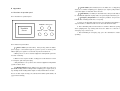
4.1 Directions of operation panel
4.2 Touch screen display and function select
4.3 Operate machine
5 Adjust, maintenance and eliminate faults on machine
5.1 Adjusting of system pressure
5.2 Maintenance of machine
5.3 Eliminate faults
5.4 List of sealing parts of hydraulic system
6
Electrical material
6.1 Main circuit diagram
6.2 I/O control diagram
6.3 Data collect
6.4 List of electric detail
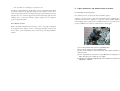
1 Safety directions
of operation.
a. The operator has to know about means of operation of the machine well.
1.1 Safety prompt
Design of the machine is in accord with safety rules for factory, the safety units
installed are in a position to protect the operators of machine and prevent any
danger by accident from machine itself. The operators should not just count on
these safety units and also have to read and understand the safety preventive
b. Do not take off the safety units, protectors, emergency stop button and
grounding wires of the machine.
c. Must know how to stop machine in an emergency.
d. Do not try to stop the running machine with an article or your hands, in
particular heating parts.
e. More than 2 people together run the machine at the same time to be
measures mentioned in the safety chapters of manual, then can start to run
definitely prohibited.
machine.
1.3.2 Only the qualified technician can do maintenance of electric
Note: unsuitable operation might harm to people and other equipments around the
machine.
1.2 Safety points before machine in operation
1.2.1 Confirmation before turn on power supply
a. Make sure to do routine inspection well as required in the safety
chapters of manual.
b. Make sure that all safety doors of machine have been closed completely.
c. Make sure that all operating switches of machine are at correct operating
position.
1.2.2 Turn on power supply
a. Make sure that the rotation of the motor of oil pump is in a correct
direction. Look into it from the rear of the motor, a direction of counter clockwise
rotation is correct.
b. Make sure that the indicate lights are normal.
c. Make sure that all safety units of machine as the protectors, a switch of
safety door, an emergency stop button and grounding wires, all are set
system, hydraulic system and mechanical system
a. Turn off the power supply before opening the door of electric cabinet.
b. Make sure that all of power sources are off, before taking off and
changing the electric parts.
c. Use the insulation tools in working.
d. Neither use a fuse that is beyond signed limit or other metal wires.
e. When changing any wire, be sure to use as the same specification and
color as original.
f. Be sure that nobody runs the machine, before turn on the power supply.
g. Do not put anything on the control box or operating place, for example,
water and food.
h. Do not touch the switches of machine or any electric parts with wet
hands.
1.4 Prevent from seriously harm to body
a. Face to the machine to operate the panel in regular procedure.
b. Do not let your hand or any parts of body stretching into the running
correctly.
machine when you bend down.
1. 3 Safety points for operating machine
machine from behind or beside.
The machine contains some heating parts, hydraulic press parts and high voltage,
reach into the domain of moving mould plate.
therefore if the operator does not follow the safety points below, the machine
might have some potential dangerous situations.
1.3.1 Operators have to be trained and carefully read the safety
points below as well as make sure to be acquainted with all means
c. When the motor is rotating, don’t let other people be close to the
d. When the motor is rotating, don’t let your hand or any parts of body
e. Follow the instruction to operate and maintain machines.
f. Do not examine and repair the mould plate when the motor is rotating.
g. Whenever leaving or having any adjustment of machine, be sure to turn
off the power supply.
h. If the machine is in un-normal condition, please inform to your chief or
instructor so that doing repair.
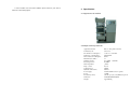
2 Specification
2.1 Appearance of machine
2.2 Major technical parameter
Applicable material:
Laminate layout:
The number of mould plates:
Dimension of mould plates:
Interval between mould plates:
Material layers (Max.):
Working pressure:
Pressure precision:
Heat temperature:
Temp. control:
Cylinder travel:
Hydraulic tank volume:
Power supply:
Power:
Productivity (cards):
Dimension:
Weight:
PVC or other plastics material
3×8or 5×5
3 each of cool and heat
420×520 mm
50mm
15
0.8~15Mpa adjustable
±0.3MPa
160°C
±0.5°C
240mm
300 liter
AC380V 50Hz 5 wires in 3-phase
13.0kW
750 cards per cycle (at 3x8)2000cards per hour
L1260×B1000×H1800mm
Appr.2000 kg
Caution: Only qualified technician can make a connection of main power supply. A
3 Installation
voltage of power supply for machine is as AC380V, if get an electric shock, it would
cause some damages of machine or might lead to injuries and deaths on people.
3.1 Environment of install
3.1.1 Install place
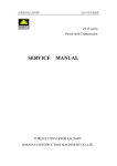
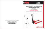
3.4.1 Must be in accordance to a circuit diagram to connect a power supply of
The place should be far away from inflammables, there is
no combustible air in workshop, do not stack any goods behind the machine.
3.1.2 Ground requirement
the machine should be installed into a standard
machine on an assigned wiring position. The machine must be in safety
grounding.
industry factory building. The installed ground should be smooth and solid. A
Ground wire
U (red)
depth of concrete pad will not be less than 200mm. If an installation is at
Electrical board
1
second floor or above, have to be sure that the bearing of floor meets
3.1.3 Environment of install
The workshop should be airtight, dustless and
have the ventilation installation.
3.1.4 The requirement of Power source Power supply is as AC380V/50Hz, 5
wires in 3-phase, ground wire is grounded reliably. Ground resistance < 0.1
2
ohm. Ground wire > 4 mm ,
Load and unload machine
Select lifting place based on the mark of gravity center. Keep the machine in
equilibrium throughout lifting. When using a crane to lift, need to select the
suitable sling rope.
The rope should be pulled straight and try first to slide
down. Do not let the rope damage the outside and any parts of the machine.
3.3
(red)
2
W
(red)
Zero N (blue)
3
N
Caution: never share a single grounding wire by two machines or more.
requirements.
3.2
V
Unpack and lay down machine
3.3.1 Check on the outer package of machine, if there is any damage, please
inform supplier. Otherwise unpack the package.
3.3.2 Level off body of machine with a level. If a floor is not smooth, try to put
some pads until making the machine level.
3.3.3 Open a cap of oil tank then fully pouring oil. Using ISO VG46 Anti-Wear
Hydraulic Fluid.
Note: Hydraulic oil must be accorded with the standards and make sure that the oil is
clean. An improper use or unclean oil could speed up the wear of oil tank and
hydraulic system.
3.4 Connection between machine and main power supply
3.4.2 After connecting the power, check a rotation of motor of oil pump, the
rotary direction should be as the same direction as the arrow point. The way to
check the rotary direction of motor: Press the start button of pump, then
pressing the stop button at once. See if the rotary direction is correct, if it is not,
swap the places of 2 input power wires of AC380V. Repeat doing as indicated
above. Make sure that the rotary direction of motor is correct.
Caution: Be sure never let the motor rotate on incorrect direction more than one
minute.
3
4 Operation
Cool button(self-lock button) Press the button, the cooling pump
starts, the cool indictor is lighting; press again(reset) to stop the pump and the
cool indictor light is off. Auto/man all are effective.
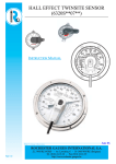
4.1 Directions of operation panel
4
Start button (reset button) In automatic mode, after press this button
for 1 second, the hydraulic oil pump starts, the system begins automatic cycle.
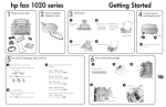
4.1.1 Illustration of operation panel
5 Emergency Stop button In an emergency situation, can press the
button to cut off heating and the motor of oil pump.
a. If there is any abnormal status in works, press this button immediately to
POWER Emergency
Touchable
Screen
stop the machine, so that find out the reason caused the abnormal status.
b. After eliminating fault, turn the button in clockwise. When the spring
clicks springing back, stop turning and release the button. It is relieved of
HEAT
COOL START
emergency stop, self-lock resets.
c. After terminating an emergency stop, press the start button to restart
operating.
4.1.2 Function of push buttons
1 Power switch (self-lock button)
After pressing down the button,
power supply is connected through, the system is power on and the power
indictor lights; press again to reset and cut off power, the indicator off.
a. When power is on, all of electrical equipments and hydraulic system are
in a state of stand-by.
b. When need to stop the machine, usually just reset the button; if no work
for a long time, pull off the power plug.
c. Only this button is at 1 position, all of electrical equipment and hydraulic
system are able to work.
2 Heating button(self-lock button) Press the button, the heat press
plates start heating and the heating indictor is lighting; press again (reset) to
stop heating and the heating indictor light is off. Auto/manual all are effective.
Note: it can heat only in selecting work, otherwise PLC alarms. If PLC alarms, cut
off power then restarting.
4.2
Touch screen display and function select
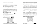
4.2.1 Initial display
Press the power button, after power supply is on, a display is showed as below:
Note: When power is on, PLC default is Work 0, must select a Work number first, then
being able to operate as below.
Display time at right column is counted time, a work goes at which pressure
level, which one begins to count down time. Above display shows the second
level remains 0.4 minute before it finishes.
4.2.3 Amend work parameter
Work parameters include heat temperature, the number of pressure level,
pressure and holding time of each pressure level. Touch
, enter
Work-P
into the display of amend work parameter:
Touch Operation
display.
, the machine goes into a work status and gets a work
4.2.2 Work display
At first select work No. when amending parameters, work 1 is selected as
above display, then doing as below procedure:
a. To amend temperature setting: touch temperature value(100.0), a number
key board is bounced as below:
Touch
Work 1
, goes into work 1 display
Work 1 display:
Touch relevant number, then touching ENT to confirm input, the number key
board is closed.
Note: temperature range is as 0.0 – 175.0
Operation of number key board:
Amend: CR, touch CR to delete number inputted.
Cancel: ES, touch ES to close the number key board
Confirm: ENT, touch ENT to confirm number inputted, the key board is closed.
Move key board: at first touch top of board then touch a position moved to, the
key board is going to be moved to the position second touched.
b. To amend the number of pressure level: touch value(4) of pressure level to
bounce number key board, then touch relevant number, last touch ENT to
confirm input, the key board is closed.
Note: the number of pressure level range is among 1 – 4.
c. To amend pressure setting: touch value (1.0) of pressure setting to bounce
the number key board, then touch relevant number, last touch ENT to confirm
input meanwhile the key board is closed.
Note: pressure setting range is: 0.0 – 15.0 as well as 1st pressure level <
2nd pressure level < 3rd pressure level < 4th pressure level; 1st pressure
level > pressure precision +0.3.
d. To amend time setting: touch value (1.0) of time setting to bounce number
key board, next touch relevant number, then touching ENT to confirm input, the
key board is closed.
Note: time setting range is as 0.0 – 99.0.
e. After finishing amend and confirm it is correct then touching
go back the work display.
RETURN
to
Note: the work parameters are only effective at this work.
4.2.4 Amend system parameters
The system parameters include pressure parameter, pressure precision and
temperature control parameter. Touch
to go into the
System-P
display of amending system parameter.
a. To amend pressure parameter: eliminate an appearance of pressure
overdoing by amending pressure parameter, normally set this parameter
among 0.80 – 1.00, the increasing or decreasing value of each amending is not
bigger than 0.02. This value is already set at factory and do not change it rashly.
If the value is bigger, pressure may overdo, otherwise if smaller, pressure may
not reach to the setting value. It is ordinary better to adjust pressure by 0.3MPa
higher than setting.
Note: pressure parameter range is 0.80 – 1.00.
b. To amend pressure precision: to determine the pressure at starting
compensating pressure by amend pressure precision, ordinary set the value as
0.3 – 0.5. For example, set pressure to 5.0MPa and pressure precision as 0.3,
when pressure is down to 4.7MPa, the hydraulic system will automatically
concentrate pressure to 5.0MPa. The hydraulic system will be easy to vibrate at
this value smaller than 0.3. Recommend to set the value as 0.3.
Note: pressure precision range as: 0.3 – 0.5.
c.
To amend temperature control parameter: to change rising speed and
control precision of temperature by amending temperature control parameter.
Touch
1 Tempera parameter
to enter into the display of amending
temperature control parameter.
Temperature control parameters have Kp, Ti and Td. Kp affect speed of
temperature rising, Ti affect temperature precision and Td affect time of taking
by temperature curve approaching setting value. Increase Kp, decrease Ti and
Td will quicken response, otherwise decrease Kp, increase Ti and Td will slow
down response. It should be around 10% by each adjusting, then making
amendment according to curve variation. Kp, Ti, Td have been set at factory, do
not amend it without PID experience. Maintenance person must take Kp, Ti and
Td on record.
Note: do not amend temperature control parameters rashly.
e. After amending and confirm it is correct then touching
back the work display.
RETURN
to go
4.2.5 Curve
Touch Curve
to show the immediate pressure and temperature system
detected in the form of curve.
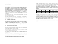
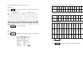
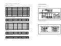
Correspondence relation between voltage and temperature:
Note: system parameters are effective on all of works.
Voltage
v
0
1
2
2.8
Temp.(°C)
0
36
72
100 108
3
3.1
3.3
3.6
3.9
4
4.2
5
110
120 130 140 144 150 180
Correspondence relation between voltage and pressure:
0
Pressure
0
Voltage
v
(MPa)
0.25 0.50 0.75 1.00 1.25 1.50 2.00 2.50 3.75
1
2
3
4
5
6
8
10
15
5
20
Touch
RETURN
, system return to work display
4.2.7 Manual
Touch
Heat 3
Off
Heat
Heat 2
Off
Heat
Heat 1
Off
Heat
Lo Pump
Stop
Running
Down
Off
Down
Up
Off
Up
Hi Pump
Stop
Running
Lower limit
Stop
Running
Upper limit
Running
Heat
Stop
1
Stop
to display the status and data of input and output detected
Heat
Status
Touch
by system.
Stop
0
4.2.6 Detect status
Running
to return to work display.
Emergency
RETUR
Run
Touch
Emergency
Abscissas show time, ordinates show pressure or temperature, data in last 30
minutes are held.
Start
Input and output status:
Manual
, system goes to manual mode and displays as below:
a. It will stop automatic circulation that shift running to manual mode, it is
necessary to press the start button again for doing work if back to running from
manual mode,
4.3
b. Touching keys are holding keys, touch once to work, touch once more to
stop.
4.3.1 Automatic operation
c. To move mould plates up fast by manual operation, need to touch
simultaneously. It is same at down move.
Hi pump and
Up
initial display showed.
Hi pump
d. Touch
move slowly.
e. Touch
Status
and
Lo pump
and
Up
the plates
Operate machine
a. Push down “Power” button, power indicator is on, system is electrified and
b. Touch “Operation” to enter work display.
c. Touch “Work parameter” key to enter parameter setting display, separately set
to shift system into select status, so that observe
temperature, pressure and time then touching “Back” key to return to work display.
about input information. At this time from the display of select status return back,
d. Select work number, check parameter and see if correct.
it still go back to manual display, not work display.
e. Push down “Heat” button, heating indicator is on and start to heat.
f. Touch
Note: to shorten heat, can move up plates to heat.
4.2.8
RETUR
, the system return to work display.
f. Heat pressure: when temperature reaches at setting, place materials, push down
Productivity
OUTPUT
Touch
, the system goes into display of production statistics.
The display helps operator to count up output. Touch a relevant number area to
call in the number keyboard, input relevant number. Accumulative production is
obtained by system counting.
Note: system counts accumulative production by the same number of sheets on two
levels.
Touch
RETURN ,
system back to work display.
“Start” button, the plates move up, pressing and compensating. Setting time is up, the
plates automatically move down, a single cycle of heat pressure is finished. If the
technical parameters for cool pressure are as the same as ones for heat pressure, then
cool and heat pressure can be done at the same time. When cool pressing, should press
down “Cool” button. If the technical parameters for cool pressure are not as the same
as ones for heat pressure, then should do cool pressure independently.
Note: cooling system is not controlled by PLC. At any status, press down “Cool”
button that can start the pump of cooling water.
g. Cool pressure: select work number, check whether the parameters are correct.
Place materials, press down “start” button and “cool” button, the mould plates move
up, pressing and compensating; Setting time is up, the plates automatically move down.
A single cycle of cool pressure is finished.
h. If on accident, press “Emergency stop” button to exit.
5 Adjust, maintenance and eliminate faults on machine
Note: Before starting lamination, should adjust a position of upper limit switch. When
mould plates push down the upper limit switch, the motion will be slowed down to
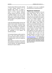
5.1 Adjusting of system pressure
ensure slow pressing. It is better to normally adjust a gap between material on top layer
and plate above it to 5 mm. The upper limit switch is behind plate right side. After
adjusting, need to lock it up. If materials’ depth is changed, need to readjust the
Note: adjusting work of system pressure done by hydraulic engineer.
Adjusting of system pressure is to be done by adjusting the pressure-regulating valve.
position of upper limit switch.
It has been done well before shipment, no touch in an ordinary situation. Regulate
4.3.2 Manual operation
pressure is 3MPa. If need to adjust, do it with reference to below figure.
value of Hight pressure system pressure is 15MPa and value of Low pressure system
When doing machine adjustment, all of start/stop of motor of oil pump, mould plates
up, mould plates down, start/stop of motor of water pump and heating of plate of each
level are able to operate independently. Above actions can be done through “Manual”
interface
(1) Loose the protective nut of pressure regulating valve;
(2) Loose the lock nut of pressure regulating valve;
(3) Turn screw clockwise to increase pressure, turn counter clockwise to
reduce pressure;
(4) to be suspended for a moment on every adjustment of rising by 2 –3
MPa, when pressure is stable, go on to adjust;
(5) Adjusting to 15 MPa then tightening the lock nut and the protective nut,
adjusting is completed.
5.3 Eliminate faults
5.2 Maintenance of machine
Appearance
Period
1
Machine must keep clean and dry, regularly clear and
clean various positions of mechanism,
1/wk
2
It is necessary to clear and lubricate various movable
parts (various guide pillars) regularly.
1/wk
3
Check various screws and nuts of connecting and tight
to see if loosed, in the light of conditions to tighten or
change.
1/month
4
Check various connection of wires to see if loosen or
cracked, then reconnecting or changing wires.
1/month
5
Measure resistance of electrothermal tubes to see if
values of 3 levels are identical, change damaged
electrothermal tube.
1/month
6
Check connection wires of tubes to see if loosed, tighten
or change.
1/month
7
Environment around the machine must be clean, dry
and no pollution.
Long term
Often
9
Observe the temperature of hydraulic oil, it should not
be higher than 60
Often
10
After the machine runs for 1 year, should change
hydraulic fluid, which grade is as ISO VG46 Anti-Wear
Hydraulic Fluid.
1/year
8
Often observe the altitude of surface of hydraulic oil,
when lower than 3/4, fill up promptly.
Elimination ways
of faults
1.Check various positions of oil pipes and connectors of pipes
between hydraulic cylinder and integrated unit, if there is any oil
leakage, then changing pipes, combined gaskets or “O” sealing
washers that are damaged.
Can not hold 2.Change hydraulic lock.
3.Check the position between pressure gauge and integrated unit, if
pressure
there is any oil leakage, make a correspondent treatment.3. If
there is no problem on what above mentioned, check inner
sealing washers of cylinder to see if damaged and make a
correspondent treatment.
1. It is as the same as above appearance.
2.Check the conjunctions of various valves and integrated unit, if
there is any leakage, treat correspondently.
Very low or no 3.Check the pipe and joint between the outage of oil cylinder and
pressure
integrated unit, if there is any leakage, treat correspondently.
4. See if an oil in the tank is enough and treat it correspondently.
5.If no trouble on the appearances above mentioned, then changing
hydraulic pump.
Temperature
rising of heat
plates is too
slow or can
not reach at
setting temp.
1.Check electrothermal tubes to see if there is short or broken
circuit, treat correspondently.
2.Check temp. sensor to see if work correctly.
3.Check solid-state relay and circuit, treat correspondently.
4.Check fuse if blown, find out reason first then changing.
1.Under indoor temp. show minus or drifted off, check connectors
of temp. sensor and temp. transmitter if damaged or loose,
Detected temp.
change or reconnect.
by PLC are 2. Indicate 180 , there is a short or thermal resistor damaged.
Check and change.
abnormal.
3. Check resistance of thermal resistor. Should be little more than
100 under indoor temp..
Substance and manner of maintenance
Item
Detected
pressure
PLC
abnormal.
by
Indicate negative or invariable, check connector of pressure
sensor if damaged or loose, change or reconnect.
5.4 List of sealing parts of hydraulic system
6 Electrical material
5.4.1 Sealing of hydraulic pressure
Specification
D=220 30
5
1
standard guide ring formaldehyde
DC24V 4.5A
220V FU1
S- -24
Q/ZB 248-77
D220
2
0 Sealing washer
GB1235-76
Rubber I-4
100 5.1
1
4
0 Sealing
GB1235-76
Rubber I-4
220 5.7
1
N
5
Piston rod sealing
Q/ZB 248-77
d160
1
W
6
Dust ring
Q/ZB 336-77
d160
1
7
Support ring
Yb
polyurethane
d160 15
2.5
24V-
DC24V 1.5A
FPO
C16T
U
V
3
4
2
FPO
A80
7
5
1
8
6
QF1
9
KM0
SB1
FU3
QF2
1
metallurgy poly-
S-35-24
PE
Piston sealing
3
FU2
24V24V+
N
2.
24V+
47856
metallurgy poly-
Qty.
MT506L
Yb
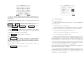
6.1 Main circuit diagram
Material
EF>@ ?AAG @@H ACC? A@ DDIB ??B @ @
Support ring
Code
1
Name
No.
10
standard guide ring formaldehyde
11 12
KM3
KM2
KM1
FU4
FU5
16
17
18
SSR1
SSR2
SSR3
19
20
21
JK2
1DT
JK4
JK1
SB4
2DT
3DT
KM1
KM2
KM3
KM0
,+
./00 +
#"$ .2 13 !"# "#% !" =
%"#$ * )
%$ (%!"$
#&
'(%
<
120W
9:
; 48 49 50
5.4.2 Sealing of hydraulic valve
14 15
JK5
FR
FR
13
JK3
Name
1
O Sealing washer
Code
GB1235-76
Material
Specification
Rubber I-4 10×1.9
Qty.
32
6.2
5.4.3 Sealing of valve unit
Name
Code
Combined sealing JB982-77
Material
Specification
Combined part
Qty.
Gasket 14
3
gasket
Output
3
Combined part
Gasket 33
1
gasket
Upper limit
Lower limit
\ O
]
\W
O^M \ KM
5.4.4 Sealing of pipe
No.
1
Name
0 Sealing washer
Code
GB1235-76
Material
Specification
Rubber I-4 16×2.4
Qty.
4
5.4.5 Sealing of meter pipe
Name
1
O Sealing washer
Code
GB1235-76
Material
Rubber I-4
Specification
6
1.9
No.
Qty.
2
PQR JS U
JV JT JW
Combined sealing JB982-77
]bM ]bW
3
PQR JN JO L
JM JK
Emergency
stop
gasket
Cycle start
Heating
control
`
cdO ]eM dcT dcW
Gasket22
Control up-electromagnet
1DT
_
Combined part
MK^ a]T a]V
]
Combined sealing JB982-77
]aM
2
Input
Z O
1
\W
O^M \ KM
No.
I/O control diagram
Motor of Lo pressure oil pump
2nd heat
Motor of Hi pressure oil pump
Control downelectromagnet
OX XM KX
Z Y[LXN U
Y\ [ XS XV XT XW
Tfg ]Te ]We cdM
_
`
No.
2DT
1st heat
3rd heat
Unload
6.3
Data collect
V7
V4
V1
V2 COM
V3
V0
o
lmn
V5
i jklm
V6 COM
Control start of High
pressure pump motor
2DT
Electroma
gnet
Down-electromagnet
KM3
Contactor
Control start of water
pump motor
3DT
Electroma
gnet
Unload-electromagn
et
RF
Thermal relay
Control oil pump motor
SQ1
Limit
switch
Upper limit
FU1
Fuse
Control and detect circuit
220V6A
SQ2
Limit
seitch
Lower limit
FU2
Fuse
Detect circuit 24V3A
SB1
Self lock
button
Power switch
FU3
Fuse
Fist level heating
220V20A
SB2
Emergenc
y stop
button
Emergency stop
FU4
Fuse
Second level heating
220V20A
SB3
Reset
button
Heating control
FU5
Fuse
Third level heating
220V20A
SB4
Self lock
button
Start of water pump
motor
SSR1
Solid-state
relay
First level heating
220V25A
SB5
Reset
button
Cycle start
SR
i
i
i
A BC
A BC
A BC
3 1
4 2
PT100
Pressure sensor (0-5V)
SR
o
o
SR
o
hi
i lmn
hi
Contactor
i jklm
KM2
PT100
Temp sensor 3
(0-5V)
PT100
Temp sensor 2 Temp sensor 1
(0-5V)
(0-5V)
6.4 List of electric detail
Code
Name
Use
Code
Name
Use
M1
Motor
Motor of Low pressure
pump
SSR2
Solid-state
relay
Second level heating
220V25A
M2
Motor
Motor of High pressure
pump
SSR3
Solid-state
relay
Third level heating
220V25A
M3
Motor
Motor of water pump
JK1
Relay
Control start of Low
pressure pump
motor
QF1
Air switch
Control main power
JK2
Relay
Control
up-electromagnet
QF2
Air switch
Control power of oil
pump motor
JK3
Relay
Control
down-electromagnet
QF3
Air switch
Control power of 220V
JK4
Relay
Control start of High
pressure pump
motor
KM0
Contactor
Control main power
JK5
Relay
Control of unload
KM1
Contactor
Control start of Low
pressure pump motor
1DT
Electroma
gnet
Up-electromagnet
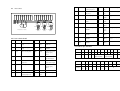
6.5 Table of tips definition
1
2
3
4
1
Definition
U
V
W
N
Motor of Low
pressure pump
Tips No
9
10
11
12
1
2
3
Upper
Lower
24V+
24V-
limit
limit
Heat
1
Heat
2
Heat
3
Tips No.
2
3
4
5
6
7
8
Line No.
Motor of High
pressure pump
4
5
Line No.
Definition
N
6
7
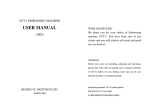
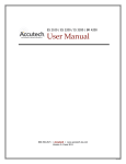
6.6 Position diagram of electric parts
7.1 Spares and tools along with machine
FPO-C16T
Temp.
Transmitter 3
pq
stuvuwr
User’s manual
240D25
240D25
SSR1
SSR2
SSR3
~
xy{| z
~| }
x
~
240D25
~
{ }
LC1-D0610
LC1-D0610
LC1-D0910
LC1-D2510
LR2-D1314
KM1
KM2 KM3
~ z
{ }
~
Note, added cool water machine
JK1 JK2 JK3 JK4JK5
KM0
1
8A
8A
8A
6A
1A
1A
C65N DC6
C65N C25
C65N D16
7.2 Material along with machine
S- -24 2.1A
RT18-32 10X38
6 pcs.
1 set
1pc.
{
S-35-24 1.5A
Electrothermal tube:
Sealing washer:
Wrench:
|
Temp.
Transmitter 2
FPO-A80
DWB-KPV
Temp.
Transmitter 1
Spares, tools and material along with machine
8
9 10 11 12
1
2 3
4 5
6
y
7
{y z
| }
y }
6
y } z
5
xy
4
y
3
y } z
2
xy
1
yz
y{
{
~
3 N
{y z
| }
y }
2
xy{| z
~| }
x
~
1