1
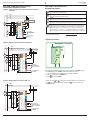
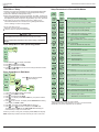
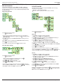
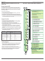
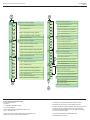
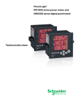
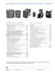
PowerLogic™ PM1000 Series Digital Meters
Quick Start Guide
PLSED309038EN
08/2010
PM1000 Series Power Meters Quick Start Guide
SECTION 1: BEFORE YOU BEGIN
PLSED309038EN
08/2010
SECTION 2: QUICK SETUP
Read and follow all safety precautions and instructions before installing and
working with this equipment.
HAZARD OF ELECTRIC SHOCK, EXPLOSION, OR ARC FLASH
Apply appropriate personal protective equipment (PPE) and follow safe electrical work
practices. In the USA, see NFPA 70E.
Only qualified electrical workers should install this equipment. Such work should be
performed only after reading this entire set of instructions.
If the equipment is not used in the manner specified by the manufacturer, the protection
provided by the equipment may be impaired.
NEVER work alone.
Before performing visual inspections, tests, or maintenance on this equipment,
disconnect all sources of electric power. Assume that all circuits are live until they have
been completely de-energized, tested, and tagged. Pay particular attention to the
design of the power system. Consider all sources of power, including the possibility of
backfeeding.
Turn off all power supplying the power meter and the equipment in which it is installed
before working on it.
Always use a properly rated voltage sensing device to confirm that all power is off.
Before closing all covers and doors, inspect the work area for tools and objects
that may have been left inside the equipment.
When removing or installing panels, do not allow them to extend into the energized bus.
The successful operation of this equipment depends upon proper handling, installation,
and operation. Neglecting fundamental installation requirements may lead to personal
injury as well as damage to electrical equipment or other property.
NEVER bypass external fusing.
NEVER short the secondary of a PT.
NEVER open circuit a CT; use the shorting block to short circuit the leads of the CT
before removing the connection from the power meter.
Before performing Dielectric (Hi-Pot) or Megger testing on any equipment in which the
power meter is installed, disconnect all input and output wires to the power meter. High
voltage testing may damage electronic components contained in the power meter.
The power meter should be installed in a suitable electrical enclosure.
Failure to follow these instructions will result in death or serious injury
Use CT1
2
Use PT1
Use PT2
Use PT3
Use CT2
Use CT3
4
3
1
RS 485
Only for PM1200
1. Connect auxiliary supply (control power) 44 to 277 VAC/DC to terminals
12 and 13 in order to power ON the power meter.
Keep
pressed for two seconds, while powering up the power meter.
The power meter directly enters into the setup menu and displays EDIT
A.PRI 100.0. This is the easiest way to enter the PROG menu setup.
Program the following setup parameters for accurate readings:
A.pri, A.sec: Set these values to match your CT primary and secondary
values. For example, if your CT ratio is 200:5, set A.pri = 200.0 and
A.sec = 5.000.
V.pri, V.sec:
Set these values to match the input voltage VLL of the circuit, if the
input voltage < 480 VAC LL. For example, if input voltage =
300 VAC LL, set V.pri = 300.0 and V.sec = 300.0.
Use potential transformer (PT/VT), if the input voltage > 480 VAC
LL. Set the V.pri and V.sec values to match the primary and
secondary of the PT(VT) respectively. For example, if PT(VT) ratio
is 11 kV:110, set V.pri = 11.00 k and V.sec = 110.0.
Select one of the following systems according to your wiring
configuration:
SYS: STAR/WYE for 3-phase 4-wire system
SYS: DLTA for 3-phase 3-wire system
SYS: 2-phase for 2-phase 3-wire system
SYS: Single-phase for single-phase 2-wire system
2. Connect the current transformers (CTs).
Ct1
CT2
CT3
1, 2
3, 4
5, 6
3. Connect the voltage inputs. Use PT(VT) if input voltage > 480 VACLL.
Pt1
PT2
PT3
Neutral
8
9
10
11
4. RS 485 (only for PM1200)
+ ve
- ve
7
14
NOTE: Refer to “SECTION 5: PROG MENU SETUP, CLR ” on page 5, for
details about PROG menu setup, A.pri, A.sec, V.pri, V.sec etc.
2
© 2010 Schneider Electric All Rights Reserved
PLSED309038EN
08/2010
PM1000 Series Power Meters Quick Start Guide
SECTION 3: INSTALLATION
Mechanical and Electrical installation
Connection Diagrams
Connecting cable
Supported System Types
Insulation Rating
Voltage Circuit
> 600 VAC
Current Rating
> 0.1 A
Current Circuit
> 600 VAC
> 7.5 A or 2.5 mm² (14 AWG) minimum
Tools and equipments
Driver
Tip
Screw head Diameter
Torque driver preferred; may use hand screwdriver.
Philips tip preferred, but you can also use flat.
Do not use Pozidriv tip.
3.5 mm (0.14 in.)
Shaft diameter
< 5 mm (0.2 in.). Diameter ³ 5 mm (0.2 in.) will get
stuck in the cover.
Torque
Tightening Torque: 0.25 to 1 N.m (2.21 to 8.85 lb-in)
Loosening Torque: 0.8 to 1 N.m (7.08 to 8.85 lb-in)
Torque > 1 N.m (8.85 lb-in) may strip the screw or break the cover.
6 mm (0.24 in.) less wire thickness
Screw Travel
System type
Meter configuration
Figure number
WYE
StAR/WyE
1
Delta, Open Delta
dLtA
2, 3
2-phase
2 Ph
Single-phase
1 Ph
4
5
Connection Diagram Symbols
Symbol
Description
Current transformer (CT)
Fuse
Shorting block
Potential transformer (PT)
Schneider Electric recommends the use of insulated sleeved U lugs
(2.5 mm²/14 AWG) for wiring terminals.
NOTE: Installations should include a disconnecting device, like a switch or circuit
breaker, with clear ON/OFF markings to turn-off the auxiliary supply (control power).
The disconnecting device should be placed within the reach of the equipment and
the operator.
Mechanical Dimensions and Panel Cut-out
Figure 1: 3-phase 4-wire WYE connection with 3 CTs and 3 PTs
L1
L2 L3
N
LINE
96.0
3.78
VER:03.04.00
3.62
50 mA to 6A
+0.8
96.0
3.78
92.0 -0.0
3.62
Mounting
LOAD
1
S/N: COYYWWDXXXX Acc Cl: 1.0
90.0
3.54
80 t o 480 Vac LL
8.00
0.31
0.25 A
44 to 277 V 50/60 Hz <5 VA
80.0
3.15
Use PT, if
VAC LL ³ 481 V
Op t i on Li st : RS 485-TH D-DM -IE
96.0
3.78
PT
+0.8
92.0 -0.0
Aux supply
(Control Power)
44 to 277 VAC/DC
Communication
(PM1200)
RS 485
Figure 2: 3-phase 3-wire delta connection with 2 CTs and 3 Pts
Remove the
mounting clamps
from the digital
meter.
L1
L2 L3
LINE
PT
Put the mounting clamps back in the digital meter
and tighten the clamps screws.
© 2010 Schneider Electric All Rights Reserved
VER:03.04.00
LOAD
RS 485
44 to 277 V 50/60 Hz <5 VA
3
Op t i on Li st : RS 485-TH D-DM -IE
50 mA to 6A
Gently slide the digital meter
through the cut-out.
S/N: COYYWWDXXXX Acc Cl: 1.0
2
80 t o 480 Vac LL
Use PT, if
VAC LL ³ 481 V
0.25 A
Aux supply
(Control Power)
44 to 277 VAC/DC
Communication
(PM1200)
3
PM1000 Series Power Meters Quick Start Guide
PLSED309038EN
08/2010
SECTION 3: INSTALLATION (Cont’d)
Connection Diagrams (Cont’d)
Figure 3: 3-phase 3-wire open delta connection with 2 CTs
and 2 PTs
L1
L2 L3
LINE
Right Key:
Go forward to sub-parameters page.
Left Key:
Go back towards main parameters page.
VER:03.04.00
Up Key:
Scroll up through the display pages at the level, within the same function
Use PT, if
VAC LL ³ 481 V
0.25 A
Down Key:
Scroll down through the display pages at the same level through all the functions
TURBO Key:
TURBO key provides one-touch access to most commonly used parameters
pages (factory-set). The TURBO pages for PM1000 series power meters are
RMS (home page), VLL A PF, VLN A F, VA W PF VA, W VAR W, VAR,
PF PF1 PF2 PF3, V% 1 2 3 A % 1 2 3, VAd RD TR, MD HR, VAh, Wh, RVAh,
Rwh, tVAh, tWh. If you are lost, use TURBO key to quickly return to RMS page.
44 to 277 V 50/60 Hz <5 VA
Op t ion Li st : RS 485-TH D-DM-IE
50 mA to 6A
S/N: COYYWWDXXXX Acc Cl: 1.0
80 t o 480 Vac LL
PT
LOAD
SECTION 4: KEYPAD SETUP
Keypad Description
Aux supply
(Control Power)
44 to 277 VAC/DC
See the online PM1000 user manual at www.powerlogic.com for more information
on keys and other features.
Communication
(PM1200)
RS 485
Keypad Operation
Figure 4: 2-phase 3-wire connection with 2 CTs
L1
L2
Navigation Concept
N
LINE
VER:03.04.00
VLN
A
F
Aux supply
(Control Power)
44 to 277 VAC/DC
RS 485
LOAD
V12
23
31
0.25A
44 to 277 V 50/60 Hz <5 VA
Op t ion Li st : RS 485-TH D-DM-IE
50 mA to 6A
S/N: COYYWWDXXXX Acc Cl: 1.0
80 t o 480 Vac LL
PT if VAC LL ³ 481 V
RMS VLL
A
PF
Communication
(PM1200)
The following example explains how you can navigate from the RMS page to
the VLN A F page, back to RMS in PM1000 series power meters.
1. From the RMS page, press
. The display shows VLL A PF.
2. Press . The display shows VLN A F.
3. Press
to go back to RMS.
Figure 5: Single-phase connection with 1 CT
L1
N
NOTE: Use the
and
to navigate to the other pages on the same level.
Use
to go to the sub-parameter pages. Use to go back to the main
parameter pages.
LINE
RS 485
44 to 277 V 50/60 Hz <5 VA
Op t ion Li st : RS 485-TH D-DM-IE
VER:03.04.00
4
S/N: COYYWWDXXXX Acc Cl: 1.0
50 mA to 6A
LOAD
80 t o 480 Vac LL
PT if VAC LL ³ 481 V
0.25 A
Aux supply
(Control Power)
44 to 277 VAC/DC
Communication
(PM1200)
© 2010 Schneider Electric All Rights Reserved
PLSED309038EN
08/2010
PM1000 Series Power Meters Quick Start Guide
SECTION 5: PROG MENU SETUP, CLR
PROG Menu ¾ Setup
The setup menu gives the complete list of user-programmable parameters.
You must configure the power meter to match the application settings
before use. Otherwise, readings will be wrong.
All the setup parameters can be re-programmed, using SET. However, the
following settings critically determine the scaling of the measured readings:
SYS (Star/wye or Delta or 2-phase or single-phase), Vpri, Vsec, Apri, Asec.
The scaling may be used to minimize the errors in reading due to
instrument transformer errors. However, wrong settings will introduce
errors in readings on other running systems.
You can enter setup menu in
Edit mode: To view or edit set parameters.
View only mode: To view the set parameters.
HAZARD OF UNINTENDED OPERATION
Only qualified personnel are authorized to set up the power meter.
Failure to follow these instructions can result in injury or equipment
damage.
Enter Setup Menu in View (Read-Only) Mode
SET
VIEW
VIEW
A.PRI
100.0
CLR
RMS
1. From RMS press . The display shows CLR.
2. Press
. The display shows SET.
3. Press
. The display shows VIEW.
4. Press . Use
or
to scroll and view the setup parameters and their
current settings.
Enter Setup Menu in Edit Mode
SET
VIEW
NOTE:
CLR
RMS
EDIT
indicates blinking/editable
1 means blinking 2
CODE
2 000
CODE
1 000
PASS
EDIT
A.PRI
100.0
1. From RMS press . The display shows CLR.
2. Press . The display shows SET.
3. Press . The display shows VIEW.
4. Press
. The display shows EDIT. CODE entry is required to edit the
setup parameters.
5. Press
for two seconds. The display shows CODE 2000 with blinking
2. The factory set CODE is 1000.
6. Press
. The display shows CODE 1000 with blinking 1.
7. Press
once or
four times to accept the new CODE value.
The display flashes PASS and then EDIT A.PRI 100.0 indicating the
successful entry to setup menu in edit mode.
Setup Parameters in View and Edit Modes
VIEW
MODE
EDIT
MODE
VIEW
A.PRI
100.0
EDIT
A.PRI
100.0
A.PRI= Current primary winding (CT)*
Input range: 1 A to 99 kA (100.0)
VIEW
A.SEC
5.000
EDIT
A.SEC
5.000
A.SEC= Current secondary winding (CT) (5.000)
VIEW
V.PRI
415.0
EDIT
V.PRI
415.0
V.PRI= Voltage primary winding (PT), line-line*
Input range: 100 V to 999 kV(415.0)
VIEW
V.SEC
415.0
EDIT
V.SEC
415.0
V.SEC= Voltage secondary winding (PT), line-line*
Input range: 80 V to 480 V ( 415.0)
VIEW
SYS
STAR
EDIT
SYS
STAR
SYS= Power system's configuration*
VIEW
LABL
123
EDIT
LABL
123
LABL= Phase labeling
Select from: 123, RYB, RST, PQR, ABC
VIEW
VA.Fn
3D
EDIT
VA.Fn
3D
VA.FN= VA function selection*
Set the VA function to: 3D, ARTH
VIEW
d.SEL
AUTO
EDIT
d.SEL
AUTO
d.SEL = Demand Selection*
Select from: auto, user
VIEW
d.PAR
VA
EDIT
d.PAR
VA
d.PAR = Demand Parameter*
Select from: VA, W, A
VIEW
d.PRD
15.00
EDIT
d.PRD
15.00
d.PRD = Demand Period
Select from: 5, 10, 15, 20, 25, 30
VIEW
BAUD
9600
EDIT
BAUD
9600
BAUD= Baud rate
Select from: 1200, 2400, 4800, 9600, 19200
VIEW
PRTY
EVn1
EDIT
PRTY
EVn1
PRTY= Parity & Stop bit settings:EVN.1 , EVN.2, ODD.1,
ODD.2, no.1, no.2
VIEW
ID
1.000
EDIT
ID
1.000
ID = RS485 Device ID number:001 to 247.
(Evn.1 = Even.1 stop bit)
VIEW
F.S%
100.0
EDIT
F.S%
100.0
F.S%= Full scale %
Set the full scale between 1 to 100
VIEW
OFLO
Wh
EDIT
OFLO
Wh
OFLO = Overflow parameter selection: Wh, VAh; INTG
clears when 9999 Run hours (almost 13.88 months)
VIEW
POLE
4.000
EDIT
POLE
4.000
POLE = Number of poles for RPM
Select from: 2, 4, 6, 8, 10, 12, 14, 16
Select from: STAR, DELTA, 2-phase, single-phase,
WYE
NOTE: Default Setup values are given in BOLD.
*Changing these values while the device is in use, is not recommended.
BAUD, PRTY, and ID are applicable only for PM1200.
NOTE: If you enter a wrong code, the display flashes FAIL, then displays
EDIT. Repeat the procedure and make sure that you enter correct code.
© 2010 Schneider Electric All Rights Reserved
5
PM1000 Series Power Meters Quick Start Guide
PLSED309038EN
08/2010
SECTION 5: PROG MENU SETUP, CLR (Cont’d)
Edit Set Parameters
This example explains how to edit the A.SEC from 5.000 to 1.000 in the
edit setup menu of PM1000 series power meter. For easy understanding,
the setup editing is explained in two parts: edit and accept setup and save
new value to setup.
Edit and Accept Setup
SET
VIEW
CLR
EDIT
RMS
CLR INTG and MD
PM1000 series power meters are equipped with INTG, where the energy
parameters are accumulated.
INTG clear - clears both INTG and MD
MD clear - clears only MD (where MD is maximum demand)
CODE
2 000
CODE
2 000
CODE
1 000
CODE
1 000
PASS
PASS
EDIT
A.PRI
100.0
EDIT
A.SEC
5.000
EDIT
A.SEC
5. 000
EDIT
A.SEC
1. 000
EDIT
A.SEC
1.000
NOTE:
NOTE:
indicates blinking/editable
2 means blinking 2
indicates blinking/editable
y means blinking y
INTG CLR
1. After you have successfully entered setup menu in edit mode (Refer to
“Enter setup menu in Edit mode” on page 5), press . The display shows
EDIT A.SEC 5.000.
2. Press . The display shows EDIT A.SEC 5.000 with blinking 5. You can
edit this value.
3. Press
four times. The display shows EDIT A.SEC 1.000 with blinking
1.
4. Press
once to accept the new value.
5. If you want to edit next parameter, press and repeat the steps.
1. From RMS, Press . The display shows CLR.
CODE entry is required to clear the INTG values.
2. Press for two seconds. The display shows CODE 2000 with blinking 2.
The factory set CODE is 1000.
3. Press . The display shows CODE 1000 with blinking 1.
4. Press
once or
four times to accept the new value.
After the successful CODE entry, the display shows CLR INTG.
5. In order to clear INTG, press
. The display shows CLR INTG y with
blinking y.
6. Press
or
to clear INTG. The display flashes PASS and then CLR INTG.
Save New Value to Setup
7. Press
8. Press
A.SEC
. The display shows CLR.
to return to RMS page.
NOTE: If you do not want to clear the integrators, press
to change the
value from CLR INTG y to CLR INTG n in step 5. Then press
or
. The
display flashes FAIL and then shows CLR INTG. Proceed to step 7.
1.000
MD CLR
NOTE:
indicates blinking/editable
y means blinking y
1. After you edit the parameter as described above, press
The display shows SAVE Y with a blinking Y.
2.Press
or
to save the new value.
The display flashes PASS and then shows EDIT.
3.Press
to go back to SET.
.
NOTE: If you do not want to save the new value, press
to change the
value from SAVE y to SAVE n in step 1. Then press
or
. The display
flashes FAIL and then shows EDIT. Proceed to step 3.
1. From RMS, Press . The display shows CLR.
CODE entry is required to clear the MD values.
2. Press for two seconds. The display shows CODE 2000 with blinking 2.
The factory set CODE is 1000.
3. Press . The display shows CODE 1000 with blinking 1.
4. Press once or
four times to accept the new value
After the successful CODE entry, the display shows CLR INTG.
5. Press . The display shows CLR MD.
6. In order to clear MD, press . The display shows CLR MD y with
blinking y.
7. Press
or to clear MD. The display flashes PASS and then CLR MD.
8. Press . The display shows CLR.
9. Press to return to RMS page.
NOTE: If you do not want to clear the MD, press
to change the value from
CLR MD y to CLR MD n in step 6. Then press
or
. The display flashes
FAIL and then shows CLR MD. Proceed to step 8.
6
© 2010 Schneider Electric All Rights Reserved
PLSED309038EN
08/2010
PM1000 Series Power Meters Quick Start Guide
SECTION 6: ENERGY INTEGRATOR INTG, OLD,
OVERFLOW
SECTION 7: PM1000 SERIES MENU HIERARCHY
Energy Integrator INTG
Your PM1000 series power meter is equipped with an energy integrator
function which provides several parameters for Energy Management: VAh,
Wh, VARh (Ind), -VARh (Cap), RUN.h (run hours), ON.h (on hours), INTR
(Interruptions / outages). All the values stored in INTG are direct readings
and have high resolution.
A few of these need explanation:
RUN.h: Indicates the period the load is ON and has run. This counter
accumulates as long as the load is ON.
ON.h: The period for which the auxiliary supply (control power) is ON.
INTR: Number of supply outages, means the number of auxiliary supply
interruptions. If the power meter auxiliary supply is from a UPS then the INTR
(number of interruptions) will be zero (as long as the UPS stays ON), even
if the voltage signals die out from time to time.
4
3
V 12
23
31
RMS
VLL
A
PF
V 1
2
3
A 1
2
3
Integrator Overflow
L%1
2
3
The energy values stored in INTG are based on V.Pri x A.Pri; they are
independent of secondary values of V and A.
The energy value readings will overflow based on V.Pri x A.Pri of the
primary settings in setup, when 9999 run hours is reached.
The energy parameter for overflow is user selectable (Wh or VAh)
through setup. By default it is Wh or by the Run hours which is fixed 9999
Run hours (almost 13.88 months).
For power systems ranging from 1 VA to 1000 MVA, the integrator will
overflow at 9999 run hours. The duration required for the integrator to
overflow will be 13.88 months if the power meter is constantly running at
full scale.
However, in case of power systems greater than 1000 MVA, the integrator
will overflow at a value less than 9999 run hours. The duration required
for the integrator to overflow will be less than a year if the meter is
constantly running at full scale.
V.PRI x A.PRI
x 1.732
VLN
Aº 1
A
2
F
3
A.UNB
V.UNB
RPM
An
VA
W
PF
Max Reading Max time to reset Max time to overflow in
the integrator in months at full scale
(Wh/VAh)
Run Hours
1 VA to 1000 VA
9999 K
9999
13.88
1 kVA to 1000 kVA
9999 M
9999
13.88
1 MVA to 1000 MVA
9999 G
9999
13.88
<9999
< 1 year
>1000 MVA
VA
W
VAR
OLD Data Register
When the integrator is cleared (manually or due to overflow), the energy
values stored in the integrator will be transferred to the OLD register.
Thus the old energy values are not lost even after the integrator is
cleared and can be viewed with the OLD parameter.
NOTE: For energy studies clear the Integrator at the end of each
observation. This transfers all the stored energy values to the OLD register,
where they are held while the Integrator begins accumulating data for
the next observation. Remember that the next time the Integrator is
cleared, the OLD values will be overwritten.
A00 1
2
3
DM
VA
VAd
Rd
TR
MD
HR
1
© 2010 Schneider Electric All Rights Reserved
VLN = Phase-Neutral voltage average
A = Current average
F = Frequency in Hz
VA = Apparent power total
W = Active power total
PF = Power factor average
V12 = RMS voltage, phase 12
V23 = RMS voltage, phase 23
V31 = RMS voltage, phase 31
V1 = RMS voltage phase 1 to neutral
V2 = RMS voltage phase 2 to neutral
V3 = RMS voltage phase 3 to neutral
A1 = RMS current, phase 1
A2 = RMS current, phase 2
A3 = RMS current, phase 3
L1% = % of load, phase 1
L2% = % of load, phase 2
L3% = % of load, phase 3
A°1 = Current phase angle, phase 1 in degrees
A°2 = Current phase angle, phase 2 in degrees
A°3 = Current phase angle, phase 3 in degrees
A.UNB = Current unbalance
V.UNB = Voltage unbalance
RPM = RPM of the motor
W1
2
3
An = Neutral current
W
VAR
PF PF 1
2
3
V00 1
2
3
VLL = Phase-Phase voltage average
A = Current average
PF = Power Factor average
VA 1
2
3
VAR1
2
3
THD
RMS = RMS value display pages are in sub level
VA1 = Volt-amperes, phase 1
VA2 = Volt-amperes, phase 2
VA3 = Volt-amperes, phase 3
W1 = Watts, phase 1
W2 = Watts, phase 2
W3 = Watts, phase 3
VAR1 = VAR, phase 1
VAR2 = VAR, phase 2
VAR3 = VAR, phase 3
PF1 = Power factor, phase 1
PF2 = Power factor, phase 2
PF3 = Power factor, phase 3
THD = Total Harmonic Distortion
V00 1 = Voltage THD, Phase 1
V00 2 = Voltage THD, Phase 2
V00 3 = Voltage THD, Phase 3
A00 1 = Current THD, Phase 1
A00 2 = Current THD, Phase 2
A00 3 = Current THD, Phase 3
DM VA = VA Demand
VAd = VA demand
Rd = Rising demand
TR = Time remaining
MD = Maximum demand
HR = On hours at which maximum demand has
occurred
7
PLSED309038EN
08/2010
PM1000 Series Power Meters Quick Start Guide
1
2
INTG VAh
Fwd
Wh
INTG Fwd = Forward Integrator
Wh = OLD Fwd Watt hours
VARh
Wh = Fwd Watt hours
VARh = OLD Fwd Reactive energy, inductive
VARh = Fwd Reactive energy, inductive
Run.h
INTG R.VAh
Rev
R.Wh
-VARh = Fwd Reactive energy, capacitive
Run.h = Fwd Run hours
VAh = OLD Fwd Volt-ampere hours
Wh
VAh = Fwd Volt-ampere hours
VARh
-VARh
OLD Fwd = OLD Forward Integrator
OLD VAh
Fwd
-VARh
-VARh = OLD Fwd Reactive energy, capacitive
Run.h
Run.h = OLD Fwd Run hours
OLD Rev = OLD Reverse Integrator
OLD R.VAh
Rev
R.VAh = OLD Reverse Volt-ampere hours
R.Wh
INTG Rev = Reverse Integrator
R.Wh = OLD Reverse Watt hours
R.VAR
R.VAh = Reverse Volt-ampere hours
R.VAR = OLD Reverse Reactive energy, inductive
-R.VAR
R.Wh = Reverse Watt hours
-R.VAR = OLD Reverse Reactive energy, capacitive
R.Run
R.VAR
R.Run = OLD Reverse Run hours
R.VAR = Reverse Reactive energy, inductive
-R.VAR
OLD t.VAh
TOT
-R.VAR = Reverse Reactive energy, capacitive
R.Run
INTG t.VAh
TOT
t.Wh
t.VAR
OLD TOT = OLD Total Integrator
t.Wh
t.VAh = OLD Total Volt-ampere hours
t.VAR
t.Wh = OLD Total Watt hours
R.Run = Reverse Run hours
INTG TOT = Total Integrator
-t.VAR
t.VAh = Total Volt-ampere hours
t.Wh = Total Watt hours
t.Run
3
t.VAR = OLD Total Reactive energy, inductive
-t.VAR = OLD Total Reactive energy, capacitive
t.Run = OLD Total Run hours
DIAG Dia1
-t.VAR
t.VAR = Total Reactive energy, inductive
Dia2
t.Run
-t.VAR = Total Reactive energy, capacitive
Dia3
DIAG = represents diagnostic pages. The values
contained in these pages are for factory testing only
Dia1 = Communication settings
On.h
Dia2 = Product model and version number
t.Run = Total Run hours
SET
VIEW
Dia3 = Display scanning for display LED check
On.h = Duration of supply ON
INTR
EDIT
INTR = Number of power interruptions
CLR
SET = Has two modes: EDIT/VIEW set parameters
VIEW = To view simultaneous setup parameter
name and value display
EDIT = To edit simultaneous setup parameter
name and value display
2
CLR = Clears INTG and MD values
4
Schneider Electric Industries SAS
35, rue Joseph Monier
CS 30323
F - 92506 Rueil-Malmaison Cedex
PowerLogic is a trademark of Schneider Electric. Other
trademarks are the property of their respective owners.
For technical support:
[email protected]
(00) + 1 250 544 3010
Electrical equipment should be installed, operated, serviced, and
maintained only by qualified personnel. No responsibility is
assumed by Schneider Electric for any consequences arising
out of the use of this material.
Contact your local Schneider Electric sales representative for
assistance or go to www.schneider-electric.com.
© 2010 Schneider Electric All Rights Reserved
PM1000 QSG v03.04.00.d15