1
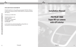
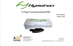
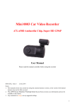
Movon Corporation
MDAS-3 Guidebook
(PC Calibration & Installation)
CONTENTS
Intro 1. MDAS-3 (Lane Departure Warning Kit) -------------------------------------------------------------------------------- 3
Intro 2. Installation Overview ------------------------------------------------------------------------------------------------------------- 4
Intro 3. Cables / Harness ------------------------------------------------------------------------------------------------------------------ 7
Chapter 1. PC Calibration (For Initial Settings / For User) ------------------------------------------------------------ 11
1. 1st STEP: PC Connection ------------------------------------------------------------------------------------------------------ 11
2. 2nd STEP: Vehicle Data File -------------------------------------------------------------------------------------------------- 12
3. 3rd STEP: Vehicle Information Check ---------------------------------------------------------------------------------- 13
4. 4th STEP: Camera Angle Setup I ------------------------------------------------------------------------------------------ 14
5. 5th STEP: Camera Angle Setup II ----------------------------------------------------------------------------------------- 15
6. 6th STEP: Hood Line Setup -------------------------------------------------------------------------------------------------- 16
7. 7th STEP: Camera Location Setup --------------------------------------------------------------------------------------- 17
8. 8th STEP: Algorithm Setup --------------------------------------------------------------------------------------------------- 18
9. 9th STEP: MDAS Setup Complete ---------------------------------------------------------------------------------------- 18
Chapter 2. PC Calibration (For Setting Modification / For User) -------------------------------------------------- 19
1. Menu Description ----------------------------------------------------------------------------------------------------------------- 19
2. How to Update Firmware ----------------------------------------------------------------------------------------------------- 19
3. How to Default System -------------------------------------------------------------------------------------------------------- 21
4. How to Change Current Settings ----------------------------------------------------------------------------------------- 22
Chapter 3. How to Join On-line Website ----------------------------------------------------------------------------- 24
Chapter 4. How to Download the CAN File ------------------------------------------------------------------------------------ 26
Cahpter 5. Analog (GPIO / For Specialist) ------------------------------------------------------------------------------------- 29
Chapter 6. RNDIS Driver Setup ------------------------------------------------------------------------------------------------------ 34
Chapter 7. Installation (With Using OBDII Adaptor) ----------------------------------------------------------------------- 40
Chapter 8. Installation (With Using Analog Cable) ------------------------------------------------------------------------ 42
Chapter 9. Operation (For Auto Calibration) ---------------------------------------------------------------------------------- 44
-2-
Intro 1. MDAS-3 (Lane Departure Warning Kit)
1.1 Introduction
Movon Advanced Driver Assistance System (MDAS) helps to drive safely by using a computer image recognition technology
to prevent unintended lane departure. The LDWS alert occurs when the driver unintentionally departures the lane without
turning signal operation while driving at 60kmh (37 mph) or over.
1.2 Notice
MDAS-3 is a driving assistant product with lane departure warning application.
MOVON doesn’t cover the defects and damages caused by careless drivers, traffic violations, illegal activities, misuses and
abnormal uses. MDAS-3 gives the warning as beep sounds when the vehicle changes the lane without proper signaling. The
final operation and judgment will be made at the discretion of the driver.
1.3 Products
[Camera & Main Cable]
[Video In-Out Cable]
[Power Cable (6Pin)]
[Analog Cable (4Pin)]
[Cable Clips & Tie]
[OBDII Adaptor (Option)]
-3-
[Micro USB Cable (5Pin)]
[User Manual]
Intro 2. Installation Overview
2.1 The position of MDAS-3’s camera unit
The camera unit has to be placed in the middle of windshield behind the rear-view mirror.
-4-
2.2 The installation process
Attach a camera unit in the middle of
windshield behind the rear-view mirror
Connect MDAS-3’s cables to both
Vehicle’s power and Vehicle’ s CAN
signal or Analog one
Connect MDAS-3’s main cables to 6
pin harness or 4 pin harness or
both.
Adjust the knob of the camera to
align the horizontality.
Carry out PC calibration.
-5-
Run a test driving
Check out LED and Beep sound
based on User Manual.
Keep everything arranged
2.3 MDAS-3’s Connection Map
CAN High
CAN Signal
CAN Low
6 Pin Connector
MDAS-3
ACC
VCC(12V / 24V)
Power
GND
Left turn
Right turn
Speed
Signals of the car
RVS(reserved)
4 Pin Connector
Multifunction Micro USB 5 PIN port
1.
PC Calibration
2. Video out (To RCA connector)
-6-
Intro 3. Cables / Harness
3.1
MDAS-3’s Main cable
-7-
3.2
6 pin cable (connection to both Power and CAN-BUS signals)
-8-
3.3
4 pin cable (connection to Analog Vehicle signals)
3.4 OBD-II Adapter (connection to both Power and CAN-BUS signal via Vehicle’s OBD-II)
-9-
- 10 -
Chapter 1. PC Calibration (For Initial Settings / For User)
This chapter describes the procedure for initial calibration settings. Please read this guide carefully and follow the below
steps.
1st STEP: PC Connection
Connect the product to the PC by using the Micro USB cable with 5 pins and start the engine. And, access to the
http://10.0.0.1/ in the internet.
[5 Pin Micro USB Cable]
1. Select the language and click the “LOGIN” button. (ID: admin / PW:1234)
* NOTE
• When connect the product to the PC, the driver installation is required. For this, please download the RNIDS
driver from www.mdas.co.kr/eng/ and install it in the PC. Before installation driver, please read the guide
manual for RNDIS driver carefully.
• This webpage (http://10.0.01) is accessible without the internet network.
- 11 -
2nd STEP: Vehicle Data File
Select the calibration type. In case the calibration is processed by using CAN, select the “Vehicle data file (mdasinfo.dat)”. In
case the calibration is processed by analog cable, select the “Analog (GPIO)”.
1. Select the “Vehicle data file (mdasinfo.dat)” button.
2. Upload the saved CAN file in the “Browse” button and click the right arrow button (
page.
) to move to the next
* NOTE
• In case the calibration through the analog cable is processed, please see the “Analog (GPIO)” chapter.
- 12 -
3rd STEP: Vehicle Information Check
This step is to make sure the CAN communication between the CAN file and the vehicle.
1. Start the engine and drive slowly.
2. Check the speed indicated in PC calibration mode and the cluster of vehicle. If the speed difference occurs
more than 5km/h, it can be modified through the speed correction button.
3. Check the turn signal indicated in PC calibration mode and the cluster of the vehicle. If the arrow icon is ON
when the vehicle’s turn signal is OFF, click the “Left turn signal correction” or “Right turn signal correction”
button.
For example, if the right arrow icon (
) is OFF when the vehicle’s turn signal is ON, click the “Right turn
signal correction” button.
- 13 -
4th STEP: Camera Angle Setup I
This step is to setup the camera angle view. Adjust the camera angle to locate the horizon between the red guide lines.
[Adjustment Knob]
- 14 -
5th STEP: Camera Angle Setup II
For better accuracy of LDW, locate the yellow dotted line in the horizon.
- 15 -
6th STEP: Hood Line Setup
Locate the red line on the hood line of vehicle to remove the useless area under the hood line.
- 16 -
7th STEP: Camera Location Setup
Measure the required length and enter the measured value. (Unit: cm)
1. Camera Height – Length from the road to the camera lens.
2. Camera Center – Length from the center of the windshield to camera lens (“-“: Left Side, “+”: Right Side)
3. Camera to Wheel – Length from the camera to the center of the wheel
4. Vehicle Width – Length from the left wheel to the right wheel
- 17 -
8th STEP: Algorithm Setup
Setup the sensitivity of LDW warning. The distance from the wheel to lane markings is moved every 20cm by each level. The
more the distance between the vehicle and the wheel, the more the LDW sensitivity is insensitive.
9th STEP: MDAS Setup Complete
Finally, all previous steps are completed.
- 18 -
Chapter 2. PC Calibration (For Setting Modification / For User)
This chapter describes the procedure for modification settings. Please read the guide carefully and follow the steps.
1. Menu Description
1) Update Firmware: Update the firmware with the latest version downloaded from www.madas.co.kr.
2) Default System: Delete the previous settings.
3) Change the Current Settings: Modify the previous configured value.
2. How to Update the Firmware
1) Access to the www.mdas.co.kr/eng/ and download the latest firmware for MDAS-3 from the notice.
- 19 -
2) Connect the product to the PC by using the Micro USB cable.
3) In the internet, access to the http://10.0.0.1.
4) Click the “Update Firmware” menu.
5) Upload the downloaded firmware file through the “Browse” button.
- 20 -
6) Click the “Update Firmware” menu.
7) If the firmware update is successfully completed, click the “OK” button.
- 21 -
8) The product will be automatically restarted again.
3. How to Default System
1) Click the “Default System” menu.
2) The system initialization is completed, click the “OK” button
- 22 -
4. How to Change Current Settings
1) Click the “Change the Current Settings” menu.
2) Modify the condition for the speed and turn signal. For details, see the 3rd STEP.
- 23 -
Chapter 3. How to Join Membership
This chapter describes the “How to Join Membership”. To download the CAN file from the website, the membership
registration is required. Please follow the below steps.
1. Access to the www.mdas.co.kr/eng/.
- 24 -
2. Click the “MY ACCOUNT” menu in the menu of the webpage.
3. Click the “Signup” menu to register the new membership.
- 25 -
4. Choose the appropriate user type between “Personal” and “Partner”. For the successful membership
application, the following information (Email Address, Password, User Name, Telephone No.) is required.
5. If the membership is successfully finished, the “Membership Completed” pop up message appears.
*NOTE
• “Personal”: Personal Customer / “Partner”: Local Agent
• In case of “Partner”, the separate approval is required from Movon Corporation.
• In case of the personal customer, the CAN file is downloaded up to 3 times.
• In phone filed, please enter the digit only (Including the country code).
- 26 -
Chapter 4. How to Download the CAN File
This chapter describes the “How to Download the CAN file”. Please read the guide carefully and follow the below steps.
1. Access to the www.mdas.co.kr/eng/.
2. Click the “MY ACCOUNT” menu in the menu of the webpage.
3. Enter the “Email” and “Password” that have been registered in membership application. And, click the “Login”
button.
- 27 -
4. In this webpage, select the vehicle to be installed the product.
For example, if the CAN file for 2014 Prius Toyota is needed, the file will be appeared as below image. And click
the document icon (
) in the “Detail” column.
- 28 -
5. Click the “CAN File Download” button. Before download, the CAN file is saved in the designated directory.
*NOTE
• The general members can download the CAN files up to 3 times.
• The business partnership can download the CAN files without limit. To register the business partner, the
separate approval is required by Movon.
- 29 -
Chaper 5. Analog (GPIO / For Specialist)
This chapter describes the procedure for the analog connection. Please read the guide carefully and follow the below steps.
1. Select the “Analog (GPIO).
2. Start the engine and drive slowly.
3. Skip this step and move to the next page.
4. Check the speed indicated in PC calibration mode and the cluster of vehicle. If the speed difference occurs more
than 5km/h, it can be modified through the speed correction button.
- 30 -
5. Check the turn signal indicated in PC calibration mode and the cluster of the vehicle. If the arrow icon is ON
when the vehicle’s turn signal is OFF, click the “Left turn signal correction” or “Right turn signal correction”
button.
For example, if the right arrow icon is OFF when the vehicle’s turn signal is ON, click the “Right turn signal
correction” button.
6. The correction for the speed and turn signal is completed, go to the next step.
- 31 -
7. Adjust the camera angle to locate the horizon between the red guide lines.
[Adjustment Knob]
8. For better accuracy of LDW, locate the yellow dotted line in the horizon.
- 32 -
9. Locate the red line on the hood line of vehicle to remove the useless area under the hood line.
10. Enter the measured value by using the tapeline.
1) Camera Height – Distance from the road to the camera lens.
2) Camera Center – Distance from the center of the windshield to camera lens (“-“: Left Side)
3) Camera to Wheel – Distance from the camera to the center of the wheel
- 33 -
4) Vehicle Width – Distance from the left wheel to the right wheel
11. Setup the sensitivity of LDW warning. The distance from the wheel to lane markings is moved every 20cm by
each level.
12. All previous steps are successfully completed.
- 34 -
Chapter 6. RNDIS Driver Setup
This chapter describes the “How to Setup the RNDIS Driver”. To access to the http://10.0.0.1 to download the CAN file, the
“RNDIS Driver Setup” in user’s PC is required. Please read the guide carefully and follow the below steps.
1. Connect the product to the PC with Micro USB cable.
2. Select the “Computer” of the “Start” and click one time with the right mouse button.
3. Select the “Properties” and click one time with the left mouse button.
- 35 -
4. Click the “Device Manager” menu of “System” one time with the left mouse button.
5. Click the “RNDIS/Ethernet Gadget” of “Other device”.
- 36 -
6. Click the “Update Driver” button.
7. Click the “Brows my computer for driver software” menu.
- 37 -
8. Select the “Network adapters” menu and click the “Next” button.
9. Select the “Microsoft Corporation” in Manufacturer and select the “Remote NDIS Compatible Device”.
the “Next” button.
- 38 -
And, Click
10. The “Update Driver Warning” pop up message appears. And, click the “Yes” button.
11. The “Installing driver software” message appears.
- 39 -
12. If the installation is completed, click the “Close” button.
- 40 -
Chapter 7. Installation (With Using OBDII Adaptor)
This chapter describes the installation procedure with using OBDII adaptor. Please read the guide carefully and follow the
below steps.
1. Installation
1) Make sure of the standard components.
[Camera & Main Cable]
[Power Cable (6Pin)]
[Video In-Out Cable]
[Cable Clips & Tie]
[Analog Cable (4Pin)]
[OBDII Adaptor (Option)]
[Micro USB Cable (5Pin)]
[User Manual]
2) Remove the double-sided tape off the product.
3) Attach the product to the windshield glass with the camera lens located in the middle of the vehicle using the
double-sided tape. After installing the product, remove the lens cap. To enhance the performance of the
product, it is recommended to install the product between left 5cm and right 5cm in the center.
* NOTE
• Clean any foreign matter and moisture from the where the product will be installed.
- 41 -
4) Adjust aligns the horizontality with using the adjustment knob of the product.
[Adjustment Knob]
5) Connect the OBDII adaptor with the 6 pin cord to the 6 pin power cable provided in the package.
[6 Pin Cord of Main Cable]
[6 Pin Cord of OBDII Adaptor]
6) Connect the OBDII adaptor to the OBD (On board Diagnostics System) port of the vehicle.
* NOTE
• Normally, OBDII port is located underneath the driver’s side of the dash or near the gear stick.
• Please connect the plug into the port appropriately. If the device is connected inappropriately, it could cause
damage or malfunction to the product.
• To find the OBDII port position by vehicle model, please visit our web site (www.mdas.co.kr/eng/) after login.
For membership registration in the website, please see the “How to Join Membership” chapter.
- 42 -
Chapter 8. Installation (With Using Analog Cable)
This chapter describes the installation procedure with using analog cable. Please read the guide carefully and follow the
below steps.
1. Remove the double-sided tape off the product.
2. Attach the product to the windshield glass with the camera lens located in the middle of the vehicle using the
double-sided tape. After installing the product, remove the lens cap. To enhance the performance of the product, it
is recommended to install the product between left 5cm and right 5cm in the center.
3. Adjust aligns the horizontality with using the adjustment knob of the product.
[Adjustment Knob]
- 43 -
4. Connect the 4 pin analog cable to the 4 pin cord of the main cable.
[4 Pin Cord of Main Cable]
5.
6.
7.
8.
[4 Pin Analog Cable]
Connect the Right & Left turn signal of 4 pin analog cable to the analog turn indicator of the vehicle.
Connect the speed signal of 4 pin analog cable to the analog turn signal indicator of the vehicle.
Connect the power cable to the 6 pin main cable.
Connect the ACC, VCC and GND in the power cable to the related fuse pin of the vehicle.
* NOTE
• Line Colors & Cable Labels
Cable Type
Line Colors
&
Labels
Power Cable (6 Pins)
Analog Cable (4 Pins)
· White Line: CAN H
· Red Line: SIG R
· Yellow Line: CAN L
· White Line: SIG L
· Blue Line: ACC
· Green Line: Speed
· Red Line: ACC
· Black Line: RSV
· Black Line: GND
• The analog turn and speed signal indicator’s position may vary according to vehicle models.
- 44 -
Chapter 9. Operation (For Auto Calibration)
This chapter describes the product operation with using OBDII adaptor. Please read the guide carefully and follow the below
steps.
1. Install the product in the vehicle and start the engine.
2. 3 LED lights will blink simultaneously and a beeping sound will occur every 2 seconds. (Checking if the vehicle
supports CAN: Controller Area Network)
3. 10 seconds later, press the “LDW” button (Middle Button), 3 LED lights will blink and beeping sound will occur for 1
minute. (Setup the hood line.)
4. Beeping sound will occur for 3 minutes and 3 LED lights will blink alternately. (Setup the optical horizon of the
camera.)
5. Finally, after all previous steps are completed, only the middle LED light should blink with a beeping sound.
* NOTE
• To complete properly the final setup, the speed should be maintained at more than 30km/h.
• To complete calibration in a short time, it is recommended to drive the vehicle in suburban and residential areas.
The time to calibrate the device is different according to the traffic circumstances.
• The right & Left LED light of the product is operated according to the turn signals.
• In the case these is a failure in the setup process, the left and right lights will blink. In this case, follow the “PC
Calibration” and “Installation with Using Analog Cable” given in this guide or visit the nearest designated
automotive repair retailer.
- 45 -