1
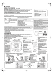
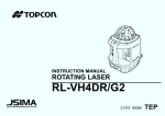
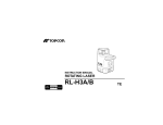
RL-H3C_CL_CS.fm Page 1 Monday, June 12, 2006 9:47 AM
INSTRUCTION MANUAL
ROTATING LASER RL-H3C
RL-H3CL
RL-H3CS
1
RL-H3C_CL_CS.fm Page 2 Monday, June 12, 2006 9:47 AM
2
RL-H3C_CL_CS.fm Page 3 Monday, June 12, 2006 9:47 AM
Introduction
Thank you for purchasing the TOPCON Rotating Laser.
The instrument has many unique features. For basic operation, rough level the
instrument and press power switch. It will self-level, then emit a rotating laser
beam.
The RL-H3CS Rotating Laser creates a level reference plane. The laser provides controls that allow the beam plane to be tilted up to 5 degrees for single
slope applications.
For superior product performance, please read these instructions carefully and
keep them in a convenient place for future reference.
3
RL-H3C_CL_CS.fm Page 4 Monday, June 12, 2006 9:47 AM
STANDARD PACKAGE COMPONENTS
Upon opening, make sure that all the followings are included:
RL-H3C / RL-H3CL
1
2
3
4
5
6
7
RL-H3C / RL-H3CL Instrument . . . . . . .
LS-70B/70C* Laser Sensor. . . . . . . . . .
Size "C" dry batteries (R14PU) . . . . . . .
9 volt dry battery (6F22/S-006P). . . . . .
Carrying case . . . . . . . . . . . . . . . . . . . .
Instruction manual. . . . . . . . . . . . . . . . .
Model-6 Laser Sensor Holder . . . . . . . .
1set
1set
4pc.
1pc.
1pc.
1vol.
1pc.
* LS-70B is included for some markets instead of LS-70C
RL-H3CS
1
2
3
4
5
6
7
RL-H3CS Instrument. . . . . . . . . . . . . . .
LS-70B Laser Sensor . . . . . . . . . . . . . .
Size "C" dry batteries (R14PU) . . . . . . .
9 volt dry battery (6F22/S-006P). . . . . .
Carrying case . . . . . . . . . . . . . . . . . . . .
Instruction manual. . . . . . . . . . . . . . . . .
Model-6 Laser Sensor Holder . . . . . . . .
1set
1set
4pc.
1pc.
1pc.
1vol.
1pc.
GENERAL HANDLING PRECAUTIONS
Before starting work or operation, be sure to check that the instrument is functioning correctly with normal performance.
When storing the instrument for long period, remove the batteries. Always
make sure instrument is dry before putting it in the carrying case. Never store
a damp instrument.
STORAGE PRECAUTIONS
Always clean the instrument after use.
Use a clean cloth moistened with neutral detergent or water.
Never use an abrasive cleaner, ether, thinner benzene, or other solvents.
Always make sure the instrument is completely dry before storing. Dry any
moisture with a soft, clean cloth.
4
RL-H3C_CL_CS.fm Page 5 Monday, June 12, 2006 9:47 AM
Safety
DISPLAY FOR SAFE USE
In order to ensure the safe use of this product, prevent any danger to the operator or others, or damage to property, important warnings are placed on the
product and inserted in the instruction manual. We recommend that you
become familiar with the meaning of these Warnings and Cautions before continuing.
Display
Meaning
WARNING
Ignoring or disregard of this display may lead
to the danger of death or serious injury.
CAUTION
Ignoring or disregard of this display may lead
to personal injury or physical damage.
•Injury refers to hurt, burn, electric shock, etc.
•Physical damage refers to extensive damage to equipment and structure or
furnishings.
Label
Beam aperture
LASER RADIATION
DO NOT STARE INTO BEAM
CLASS 2 @LASER PRODUCT
CAUTION
LASER RADIATION
DO NOT STARE INTO BEAM
WAVE LENGTH 630-685nm
1mW MAXIMUM OUTPUT
DIODE LASER
5
CLASSII LASER PRODUCT
RL-H3C_CL_CS.fm Page 6 Monday, June 12, 2006 9:47 AM
WARNINGS AND CAUTIONS
WARNING
• There is a risk of fire, electric shock or physical harm if you attempt to
disassemble or repair the instrument yourself.
This is only to be carried out by TOPCON or an authorized dealer, only !
• May ignite explosively.
Never use an instrument near flammable gas, liquid matter, and do not use in a coal
mine.
• Cause eye injury or blindness.
Do not stare into beam.
• Risk of fire or electric shock.
Do not use a wet battery.
• Battery can cause explosion or injury.
Do not dispose in fire or heat.
•The short circuit of a battery can cause a fire.
Do not short circuit battery when storing it.
CAUTION
• Use of controls or adjustment or performance of procedures other than
those specified herein may result in hazardous radiation exposure.
• Do not stand or sit on the carrying cases.
It could overturn, causing injury.
• Do not use a damaged instrument case.
It could accidentally open causing damage to the instrument or injury to people.
• Do not place yourself or a reflecting object in the path of the laser beam.
If using the laser outside, avoid positioning it anywhere near eye level to avoid any
possibility of it striking someone in the eye. If this should happen, visibility could be
temporarily impaired, causing disorientation and possible accidental injury.
• Please note that the tips of tripod can be hazardous, be aware of this when
setting up or carrying the tripod.
• Do not allow skin or clothing to come into contact with acid from the batteries, if this does occur then wash off with copious amounts of water and
seek medical advice.
• Do not place instrument on unstable platform, surface or tripod.
If using tripod, make sure instrument is securely attached.
• Risk of injury by falling down a tripod and an instrument.
Always check that the screws of tripod are tightened.
6
RL-H3C_CL_CS.fm Page 7 Monday, June 12, 2006 9:47 AM
Exceptions from Responsibility
1
2
3
4
5
6
The user of this product is expected to follow all operating instructions and
make periodic checks of the product’s performance.
The manufacturer, or its representatives, assumes no responsibility for
results of a faulty or intentional usage or misuse including any direct, indirect, consequential damage, and loss of profits.
The manufacturer, or its representatives, assumes no responsibility for
consequential damage, and loss of profits by any disaster, (an earthquake,
storms, floods etc.), fire, accident, or an act of a third party and/or a usage
in other than usual conditions.
The manufacturer, or its representatives, assumes no responsibility for any
damage, and loss of profits due to a change of data, loss of data, an interruption of business etc., caused by using the product or an unusable product.
The manufacturer, or its representatives, assumes no responsibility for any
damage, and loss of profits caused by usage other than explained in the
user manual.
The manufacturer, or its representatives, assumes no responsibility for
damage caused by wrong movement, or action due to connecting with
other products.
Laser Safety
This product uses a visible laser beam, and is manufactured and sold in accordance with “Performance Standards for Light-Emitting Products” (FDA/BRH 21
CFR 1040) or “Radiation Safety of Laser Products, Equipment Classification,
Requirements and User’s Guide” (IEC Publication 60825-1) provided on the
safety standards for laser products. As per the said standard, this product is
classified as a “Class ll Laser Product” or “Class 2 Laser Product”.
This is a simple product to operate and does not require training from a laser
safety officer.
In case of any failure, do not disassemble the instrument.
Contact TOPCON or your TOPCON dealer.
7
RL-H3C_CL_CS.fm Page 8 Monday, June 12, 2006 9:47 AM
Nomenclature and functions
RL-H3C / RL-H3CL
6
7
1
8
2
3
9
4
5
10
11
12
RL-H3C / RL-H3CL
8
RL-H3C_CL_CS.fm Page 9 Monday, June 12, 2006 9:47 AM
1.
Manual mode ON (Red LED)
2.
Height alert OFF (Red LED)
3.
Height alert OFF switch
Auto leveling does not function.
Height alert does not function.
OFF:Push twice continuously.
ON:Push once.
4.
Manual mode ON switch
ON:Push twice continuously.
OFF:Push once.
5.
6.
7.
Handle
Protective glass
Rotary head
8.
Battery power (Red LED)
Laser beam emits from here.
Blinking: The power is low, but laser is still usable. (Blinking continues for one
minute.)
On Solid: Dead batteries. Replace the batteries with new ones. (The lamp is solid
for five minutes, then turned off automatically.)
9.
Auto leveling (Green LED)
Blinking slowly: Auto levelling is in process.
Blinking quickly: Auto levelling is almost complete.
On Solid: Auto levelling is complete.
10. Power switch
Turn the instrument ON or OFF.
11. Battery door knob
12. Battery door
Height alert function
(Safety lock system)
When auto-leveling and height alert function are active, after the laser beam
emits for one minute, this function prevents the instrument from operating if it
is disturbed. This insures accurate control. If the unit is disturbed, all lamps will
blink except battery power lamp. The elevation (height of instrument) should
be verified and re-established if necessary. This function is not active in the
manual mode.
Note
In manual mode
•Auto-leveling function is not active.
•Height alert function is not active.
9
RL-H3C_CL_CS.fm Page 10 Monday, June 12, 2006 9:47 AM
LS-70B/70C (Laser Sensor)
1
2
3
(1 9/16")
4
5
6
7
1.
2.
On-Grade Index
Beam receiving window
3.
Indicator
Turn the beam receiving window side towards RL-H3C to detect the laser beam.
Detect the on-grade position “---” by moving the Laser Sensor up and down. Directional
arrows and audio signals assist in locating the on-grade position as the laser strikes the
beam receiving window. (Top of Laser Sensor is 40mm (1 9/16")from on-grade index
for offset marking.)
LS-70B:The indicators are located on front and back sides of the instrument.
LS-70C:The indicator is located only on front side.
4.
On-Grade precision switch
Two on-grade precision options are available, normal precision and high precision. By
pressing this switch, the precision options are switched alternately. Confirm the precision choice by the indicator. (Normal precision is the default setting each time the sensor is turned on.
See LS-70B/70C Indicator diagram below.)
5.
Power switch
The power switch turns ON or OFF by pressing. If the power switch is turned ON, all
signs will be displayed on the indicator for a second with a beep sound.
6.
7.
Buzzer speaker
Buzzer sound switch
Volume of the sensor buzzer can be alternately switched to LOW/LOUD/OFF by pressing the switch.
Auto shut off function
The power will be turned off automatically if no laser beam is detected for approx.
30 min. (To turn on the laser sensor, press the power switch again.)
10
RL-H3C_CL_CS.fm Page 11 Monday, June 12, 2006 9:47 AM
RL-H3CS
8
9
10
1
2
11
3
4
5
12
6
7
13
14
15
RL-H3CS
11
RL-H3C_CL_CS.fm Page 12 Monday, June 12, 2006 9:47 AM
1.
Slope lamp (Green LED)
2.
Slope key
3.
Manual mode ON (Red LED)
4.
Height alert OFF (Red LED)
5.
Height alert OFF switch
Red: Error.
Tilts beam plane in direction of arrow.
Auto leveling does not function.
Height alert does not function.
OFF: Push twice continuously.
ON: Push once.
6.
Manual mode ON switch
OFF: Push twice continuously.
ON: Push once.
7.
8.
9.
10.
Handle
Sight
Protective glass
Rotary head
Laser beam emits from here.
11. Battery power (Red LED)
Blinking: The power is low, but laser is still usable. (Blinking continues for one
minute.)
On Solid: Dead batteries. Replace the batteries with new ones. (The lamp is solid
for five minutes, then turned off automatically.)
12. Auto leveling (Green LED)
Blinking slowly: Auto levelling is in process.
Blinking quickly: Auto levelling is almost complete.
On Solid: Auto levelling is complete.
13. Power switch
Turn the instrument ON or OFF.
14. Battery door knob
15. Battery door
Height alert function
(Safety lock system)
When auto-leveling and height alert function are active, after the laser beam
emits for one minute, this function prevents the instrument from operating if it
is disturbed. This insures accurate control. If the unit is disturbed, manual
mode ON lamp, height alert OFF lamp and auto leveling lamp will blink simultaneously. The elevation (height of instrument) should be verified and reestablished if necessary. This function is not active in the manual mode.
Note
In manual mode
•Auto-leveling function is not active.
•Height alert function is not active.
•Setting slope function is not active.
12
RL-H3C_CL_CS.fm Page 13 Monday, June 12, 2006 9:47 AM
LS-70B (Laser Sensor)
1
2
3
4
(1 9/16")
5
6
7
1.
2.
On-Grade Index
Beam receiving window
3.
Indicator
Turn the beam receiving window side towards RL-H3CS to detect the laser beam.
Detect the on-grade position “---” by moving the Laser Sensor up and down. Directional arrows and audio signals assist in locating the on-grade position as the laser
strikes the beam receiving window. (Top of Laser Sensor is 40mm (1 9/16")from ongrade index for offset marking.)
LS-70B:The indicators are located on front and back sides of the instrument.
4.
On-Grade precision switch
Two on-grade precision options are available, normal precision and high precision.
By pressing this switch, the precision options are switched alternately. Confirm the
precision choice by the indicator. (Normal precision is the default setting each time
the sensor is turned on. See LS-70B/70C Indicator diagram below.)
5.
Power switch
The power switch turns ON or OFF by pressing. If the power switch is turned ON, all
signs will be displayed on the indicator for a second with a beep sound.
6.
7.
Buzzer speaker
Buzzer sound switch
Volume of the sensor buzzer can be alternately switched to LOW/LOUD/OFF by
pressing the switch.
Auto shut off function
The power will be turned off automatically if no laser beam is detected for
approx. 30 min. (To turn on the laser sensor, press the power switch again.)
13
RL-H3C_CL_CS.fm Page 14 Monday, June 12, 2006 9:47 AM
BATTERY REPLACEMENT
1 Remove the battery cover by turning battery cover knob to “OPEN” side.
2 Remove the batteries by pulling out the slide plate.
3 Install the new batteries referring to the illustration on the battery cover.
*1, *2, *3
4 Install the battery cover. By using a coin, tighten the battery cover knob to
“CLOSE” side until the knob does not turn.*4
*1 Replace all 4 batteries with new ones at the same time. Do not mix used and new batteries, and do not mix different types of batteries together.
*2 Use alkaline dry cells. (Dry cells for movement confirmation are packed in shipment.)
Nickel hydrogen dry cells and nickel cadmium dry cells can be used too, but the operating time is different from the time of alkaline dry cells.
*3 Generally, performances of dry cell deteriorate temporarily in low temperature, but recover in normal temperature.
*4 It is important to use a coin or other tool to make sure cover is firmly closed to seal outwater.
Slide plate
Laser Sensor
1 Press the lid in the direction of the arrow to lift.
2 Remove the battery and replace with a new 9v alkaline battery.
3 Press the lid down and click to close.
14
RL-H3C_CL_CS.fm Page 15 Monday, June 12, 2006 9:47 AM
EXAMPLES OF TYPICAL USE
Using Laser Sensor On Rod
154
153
152
Level Vial
Laser Sensor Holder
151
150
149
Clamp Knob
148
147
146
Laser Sensor
gnkcdq|U
131
139
138
137
136
135
134
133
132
131
15
RL-H3C_CL_CS.fm Page 16 Monday, June 12, 2006 9:47 AM
Operation
HOW TO OPERATE
1
2
3
4
5
6
Set the instrument to the tripod or smooth surface.
Make sure instrument is roughly level (± 3°).
Press power switch (ON).
Press power switch on laser sensor (ON).
Select the precision mode by pressing the On-Grade precision switch.
Locate the on-grade position “---” by moving the laser sensor up and down.
LS-70B Indicator
When using the
Laser Sensor with
other select Topcon lasers, these
symbols alert user
if laser batteries
are low or if laser
has been disturbed. These
symbols are not
active when used
with the Rotating
High precision mode
Normal precision mode
Above grade indicator
Move the sensor down.
Audio signal:High pitch, frequent beep
On-Grade position
Audio signal:Continuous beep sound
Below grade indicator
Move the sensor up.
Audio signal:Lower pitch, slower frequency
Battery remaining display
1 Mark the position of On-Grade index.
(Top of the Laser Sensor is 40mm [1 9/16"] from index for offset marking.)
16
RL-H3C_CL_CS.fm Page 17 Monday, June 12, 2006 9:47 AM
RL-H3CS
Aligning Direction of Slope
When using the laser to set the slope, the laser must be properly aligned so
the slope axis of the laser beam is parallel to the desired direction of slope.
The sight on top of the instrument is calibrated to the slope axis of the laser
beam. Follow the steps below to align the laser to the desired direction of
slope:
1 Establish a target line parallel to desired direction of slope.
2 Set up the laser over this line (drop a plumb bob from the tripod mounting
screw).
3 Rough align the instrument to the direction of slope. Make sure it is properly
oriented for the slope to be set.
4 Using the sight, position the instrument so the sight is centered on the target. (see illustration below)
Target
[Setting slope]
Operating procedure
(Setting slope)
1 Press Power switch ON.
You can set the slope after autoleveling is completed.
Key
operation
Power
switch
Lamp display
(Refer to the illustration above)
During auto-leveling: Lamp B (Green) blinks.
After auto-leveling is completed: Lamp B
(Green) lights.
2 Press either Slope key once. The
laser beam begins to move in the
direction of the arrow on the key.
After autoleveling is
completed.
Slope key
Lamp E (Green) blinks quickly.
3 Press Slope key again to stop the
laser beam.
4 Press Slope key to fine adjust the
slope.
Beam movement begins slowly,
then increases depending on how
long the Slope key is pressed.
The blinking speed of the lamp
provides a visual indication of the
beam movement speed.
Slope key
Lamp E (Green) lights.
Slope key
When Slope key is not pressed:
Lamp E (Green) lights.
Slope key Lamp E (green) Beam movement
Press for a shorter time :Blinks slowly :Moves
slowly
5 Press Power switch OFF to cancel the slope setting.
Power
switch
Å@Å@
↓Å@Å@Å@Å@
Å@Å@Å@Å@ ↓
↓
Press for a longer time :Blinks quickly :Moves
quickly
All lamps are OFF.
17
RL-H3C_CL_CS.fm Page 18 Monday, June 12, 2006 9:47 AM
Operating procedure
(Recalling slope)
Key
operation
Lamp display
(Refer to the illustration above)
1 To recall the previous slope setting
(the setting before power was
OFF), press Power switch ON
while pressing either the right or
left Slope key. The slope can then
be adjusted as described in step 4
above.
• When the Power switch is ON
without the Slope key pressed, the
laser beam will return to level.
Slope key
+
Power
switch
When Slope key is not pressed: Lamp E
(Green) lights.
Slope key
Lamp E (green) Beam movement
Press for a shorter time : Blinks slowly :
Moves slowly
Å@Å@
↓Å@Å@Å@Å@
Press for a longer time :
Moves quickly
E
A
B
C
D
Manual mode can be activated while the slope is
set.
For information about Manual mode ON/OFF,
refer to "NOMENCLATURE AND FUNCTIONS".
Check the beam often during slope use for slope
accuracy. Check instrument calibration periodically (see below).
18
Å@Å@Å@Å@ ↓
Blinks quickly :
↓
RL-H3C_CL_CS.fm Page 19 Monday, June 12, 2006 9:47 AM
Checks and adjustments
1 Checking and adjusting calibration
Horizontal calibration of the laser beam can be checked by the user.
[Checking]
1 Set up a tripod approx. 50m (160ft) from a wall. Mount the instrument on the
tripod, facing the X1 side toward the wall.
2 Turn the instrument on and allow auto-leveling to complete.
3 Put the laser sensor in fine detection mode by pressing the On-Grade precision switch.
4 By using the laser sensor, mark the center position of laser beam on the
wall. (X1)
5 Turn off the instrument.
Loosen the tripod screw, rotate the instrument 180 degrees and re-secure it
on the tripod. The X2 side of the instrument faces toward the wall.
When rotating the instrument, avoid changing the height.
6 Turn the unit on again and allow auto-leveling to complete.
7 By using the laser sensor, mark the center position of laser beam on the
wall. (X2)
8 If the difference value of marked two laser beam heights (difference value of
X1 and X2) are less than the value specified in the next table, adjustments
are not needed. If the difference value is greater than the value specified in
the table, adjust the instrument as described below. *
9 Check the X1 (handle) side as the same way.
Type
Value
RL-H3C
7 mm
RL-H3CL
5 mm
RL-H3CS
7 mm
X1
Y2
Y1
*If the difference value is
greater than 60mm (2 3/8
inches), contact your Topcon
dealer.
X2
19
RL-H3C_CL_CS.fm Page 20 Monday, June 12, 2006 9:47 AM
[To calibrate the X axis ]
1 Face the X1 side of the instrument (panel side) toward a wall, press the
Power switch while pressing the height alert OFF switch.
Then the height alert OFF lamp will light, and manual mode ON lamp will
blink.
2 Press the height alert OFF switch to calibrate the X axis. The manual mode
ON lamp will light. When auto-leveling finishes, the laser beam will emit.
3 Using the laser sensor, mark the on-grade height of laser beam on a wall.
4 Rotate the instrument 180 degrees to face X2 side toward a wall.
5 In the same way as step 3 , mark the on-grade height of laser beam on a
wall.
6 By pressing the manual mode ON switch (laser beam moves up), or Power
switch (laser beam moves down), adjust the on-grade height of the beam
until it is precisely centered between the marks made in steps 3 and 5 .
7 Press the height alert OFF switch to memorize the new laser beam calibration. The height alert OFF lamp will blink. Power will shut off automatically
when the calibration memorization is complete.
[To calibrate the Y axis ]
1 Face the Y1 side of the instrument (handle side) toward a wall, press the
Power switch while pressing the height alert OFF switch.
Then the height alert OFF lamp will light, and manual mode ON lamp will
blink.
2 Press the Power switch again. The auto leveling lamp will light.
3 Press the height alert OFF switch to calibrate the Y axis. The auto leveling
lamp will light.
4 Using the laser sensor, mark the on-grade height of laser beam on a wall.
5 Rotate the instrument 180 degrees to face Y2 side toward a wall.
6 In the same way as step 4 , mark the on-grade height of laser beam on a
wall.
7 By pressing the manual mode ON switch (laser beam moves up), or Power
switch (laser beam moves down), adjust the on-grade height of the beam
until it is precisely centered between the marks made in steps 4 and 6.
8 Press the height alert OFF switch to memorize the new laser beam calibration. The height alert OFF lamp will blink. Power will shut off automatically
when the calibration memorization is complete.
To discontinue calibration the instrument, press the Power switch while
pressing the height alert OFF switch.
When calibration is memorizing, if the height alert lamp continues to blink
quickly and power does not shut-off automatically, please contact your local
Topcon dealer.
20
RL-H3C_CL_CS.fm Page 21 Monday, June 12, 2006 9:47 AM
Laser point of X1
laser sensor
X1 Laser beam
X1
Wall
Approx. 50m
X1
X2 Laser beam
X2
Approx. 50m
2 Checking cone error
Perform the following check after completing horizontal calibration procedure.
[Checking]
1 Set up the laser centered between two walls approximately 40m (131ft)
apart. Orient the instrument so one axis, either X or Y, is facing the walls.
2 Locate and mark the position of the rotating laser beam on both walls using
the laser sensor.
3 Turn off the instrument and move the instrument closer to wall A (1m to 2m /
3 ft to 6 ft).
Do not change the axis orientation of the instrument. Turn the instrument
on.
4 Again locate and mark the position of the rotating laser beam on both walls
using the laser sensor.
21
RL-H3C_CL_CS.fm Page 22 Monday, June 12, 2006 9:47 AM
5 Measure the distance between the first and second marks on each wall.
If the difference between each set of marks is less than 4mm (5/32 of an
inch), no error exists.
*If the difference value is greater than 4mm(5/32 inch), contact your
Topcon dealer.
Cone error
Datum position
Wall B
Wall A
Approx. 40m
Wall B
Wall A
22
RL-H3C_CL_CS.fm Page 23 Monday, June 12, 2006 9:47 AM
3 Error Code
Use the table below to determine operation errors indicated by blinking lamps
on the control panel. If corrective action listed does not correct error, please
contact your local Topcon dealer.
Lamp Indication
Error Code
Corrective Action
Lamp B, C and D
blink in turn
Auto-leveling
range error
Correct tilt of the instrument until it
less than 3 degrees.
Lamp A lights
Battery power
error
Replace all 4 batteries with new
ones at the same time.
Lamp B, C and D
blink simultaneously
Height alert error
Turn power off, rough level the instrument, then turn power on again.
Check height of laser beam as it may
have changed.
Lamp D blinks
quickly
Calibration error
Repeat calibration procedure.
If error repeats contact your local
Topcon dealer.
Lamp E (Red) lights
Lamp B, C and D
blink in turn
Slope setting
range error
Push the slope key of the opposite
side, and align slope.
Lamp A, B, C and D
blink simultaneously
Internal error
Turn power off, then on again.
If error repeats contact your local
Topcon dealer.
RL-H3C / RL-H3CL
RL-H3CS
E
A
A
B
B
C
C
OFF
D
ON
POWER
D
MANU
23
RL-H3C_CL_CS.fm Page 24 Monday, June 12, 2006 9:47 AM
Specifications
RL-H3C
Accuracy
: ±3.6mm/50m (±15 ”)
Automatic correction range : ±3°
Beam detecting range
: Approx. 2m~300m diameter
(6ft~980ft)
Rotational speeds
: 600r.p.m
Laser source
: Laser diode (Visible, Red)
Laser power output
: 0.8mW (Max.)
Laser class
: Class 2 laser product
Power supply
: Four C size alkaline manganese dry batteries
Operating time
: Approx. 60 hours at +20°C (+68°F)
Protection against
water and dust : IP56 (Based on the standard IEC60529)
Operating temperature
: -20°C~+50°C (-4°F~+122°F)
Dimensions
: 167(L)x182(W)x189(H)mm
(6.5x7.1x7.4 in)
Weight
: 1.9kg[4.1lbs] (With dry batteries)
LS-70B/70C
Beam detection window
Beam detection precision
:
:
:
Beam detection indication :
Power source
:
Operating time
:
Auto shut-off delay
Operating temperature
Dimensions
:
:
:
Weight
:
50mm (2.0 in)
High precision
: ±1mm(±0.04 in)
Normal precision : ±2mm(±0.08 in)
Liquid crystal and buzzer
DC 9V alkaline (dry) battery
Approx. 80 hours at +20°C (+68°F)
(Using alkaline manganese dry batteries)
Approx. 30 minutes without beam detection
-20°C~+50°C (-4°F~+122°F)
165(L)x78(W)x26(H)mm
(6.5x3.0x1.0 in)
0.25 kg [0.55 lbs] (With dry batteries)
24
RL-H3C_CL_CS.fm Page 25 Monday, June 12, 2006 9:47 AM
RL-H3CL
Accuracy
: ±2.4mm/50m (±10 ”)
Automatic correction range : ±3°
Beam detecting range
: Approx. 2m~500m diameter
(6ft~1640ft)
Rotational speeds
: 600r.p.m
Laser source
: Laser diode (Visible, Red)
Laser power output
: 0.9mW (Max.)
Laser class
: Class 2 laser product
Power supply
: Four C size alkaline manganese dry batteries
Operating time
: Approx. 60 hours at +20°C (+68°F)
Protection against
water and dust
: IP56 (Based on the standard IEC60529)
Operating temperature
: -20°C~+50°C (-4°F~+122°F)
Dimensions
: 167(L)x182(W)x189(H)mm
(6.5x7.1x7.4 in)
Weight
: 1.9kg[4.1lbs] (With dry batteries)
LS-70B/70C
Beam detection window
Beam detection precision
:
:
:
Beam detection indication :
Power source
:
Operating time
:
Auto shut-off delay
Operating temperature
Dimensions
:
:
:
Weight
:
50mm (2.0 in)
High precision
: ±1mm(±0.04 in)
Normal precision : ±2mm(±0.08 in)
Liquid crystal and buzzer
DC 9V alkaline (dry) battery
Approx. 80 hours at +20°C (+68°F)
(Using alkaline manganese dry batteries)
Approx. 30 minutes without beam detection
-20°C~+50°C (-4°F~+122°F)
165(L)x78(W)x26(H)mm
(6.5x3.0x1.0 in)
0.25 kg [0.55 lbs] (With dry batteries)
25
RL-H3C_CL_CS.fm Page 26 Monday, June 12, 2006 9:47 AM
RL-H3CS
Accuracy
:
Automatic correction range :
Beam detecting range
:
Rotational speeds
:
Laser source
:
Laser power output
:
Laser class
:
Power supply
:
Operating time
:
Protection against
water and dust
:
Operating temperature
:
Dimensions
:
Weight
±3.6mm/50m (±15 ”)
±5°
Approx. 2m~300m diameter (6ft~980ft)
600 r.p.m
Laser diode (Visible, Red)
0.8 mW (Max.)
Class 2 laser product
Four C size alkaline manganese dry batteries
Approx. 60 hours at +20°C (+68°F)
IP56 (Based on the standard IEC60529)
-20°C~+50°C (-4°F~+122°F)
167(L)x182(W)x193(H)mm
(6.5x7.1x7.6 in)
: 1.9 kg[4.1lbs] (With dry batteries)
LS-70B
Beam detection window
Beam detection precision
:
:
:
Beam detection indication :
Power source
:
Operating time
:
Auto shut-off delay
Operating temperature
Dimensions
:
:
:
Weight
:
50 mm (2.0 in)
High precision
: ±1 mm(±0.04 in)
Normal precision : ±2 mm(±0.08 in)
Liquid crystal and buzzer
DC 9 V alkaline (dry) battery
Approx. 80 hours at +20°C (+68°F)
(Using alkaline manganese dry batteries)
Approx. 30 minutes without beam detection
-20°C~+50°C (-4°F~+122°F)
165(L)x78(W)x26(H)mm
(6.5x3.0x1.0 in)
0.25 kg [0.55 lbs] (With dry batteries)
26
RL-H3C_CL_CS.fm Page 27 Monday, June 12, 2006 9:47 AM
27
RL-H3C_CL_CS.fm Page 28 Monday, June 12, 2006 9:47 AM
TOPCON (GREATBRITAIN) LTD.
TOPCON POSITIONING SYSTEMS, INC.
HEAD OFFICE
5758 West Las Positas Blvd., Pleasanton, CA 94588, U.S.A.
Phone: 925-460-1300 Fax: 925-460-1315 www.topcon.com
Topcon House Kennet Side, Bone Lane, Newbury, Berkshire RG14 5PX U.K.
Phone: 44-1635-551120 Fax: 44-1635-551170
[email protected] [email protected]
TOPCON CALIFORNIA
3380 Industrial Blvd, Suite 105, West Sacramento, CA 95691, U.S.A.
Phone: 916-374-8575 Fax: 916-374-8329
TOPCON SOUTH ASIA PTE. LTD.
TOPCON MIDWEST
Blk 192 Pandan Loop, Pantech Industrial Complex, #07-01, Singapore 128381
Phone: 62780222 Fax: 62733540 www.topcon.com.sg
891 Busse Road, Elk Grove Village, IL 60007, U.S.A.
Phone: 847-734-1700 Fax: 847-734-1712
TOPCON AUSTRALIA PTY. LTD.
408 Victoria Road, Gladesville, NSW 2111, Australia
Phone: 02-9817-4666 Fax: 02-9817-4654 www.topcon.com.au
TOPCON EUROPE B.V.
Essebaan 11, 2908 LJ Capelle a/d IJssel, The Netherlands.
Phone: 010-4585077 Fax: 010-4585045 www.topconeurope.com
TOPCON INSTRUMENTS (THAILAND) CO., LTD.
77/162 Sinn Sathorn Tower, 37th Fl.,
Krungdhonburi Rd., Klongtonsai, Klongsarn, Bangkok 10600 Thailand.
Phone: 662-440-1152~7 Fax: 662-440-1158
TOPCON BELGIUM
Preenakker 8, 1785 Merchtem, Belgium
Phone: 052-37.45.48 Fax: 052-37.45.79
TOPCON INSTRUMENTS (MALAYSIA) SDN. BHD.
TOPCON DEUTSCHLAND G.m.b.H.
Excella Business Park Block C, Ground & 1st Floor, Jalan Ampang Putra,
Taman Ampang Hilir, 55100 Kuala Lumpur, MALAYSIA
Phone: 03-42701068 Fax: 03-42704508
Weidkamp 180, 45356 Essen, GERMANY
Phone: 0201-8619-100 Fax: 0201-8619-111 [email protected]
www.topcon.de
TOPCON KOREA CORPORATION
TOPCON S.A.R.L.
2F Yooseoung Bldg., 1595-3, Seocho-Dong, Seocho-gu, Seoul, 137-876, Korea.
Phone: 82-2-2055-0321 Fax: 82-2-2055-0319 www.topcon.co.kr
89, Rue de Paris, 92585 Clichy, Cedex, France.
Phone: 33-1-41069490 Fax: 33-1-47390251 [email protected]
TOPCON OPTICAL (H.K.) LIMITED
TOPCON ESPAÑA S.A.
HEAD OFFICE
Frederic Mompou 5, ED. Euro 3, 08960, Sant Just Desvern Barcelona, Spain.
Phone: 93-473-4057 Fax: 93-473-3932 www.topconesp.com
MADRID OFFICE
Avenida Burgos, 16E, 1∞28036, Madrid, Spain.
Phone: 91-302-4129 Fax: 91-383-3890
TOPCON SCANDINAVIA A. B.
Neongatan 2 S-43151 Mölndal, SWEDEN
Phone: 031-7109200 Fax: 031-7109249
2/F., Meeco Industrial Bldg., No. 53-55 Au Pui Wan Street, Fo Tan Road,
Shatin, N.T., Hong Kong
Phone: 2690-1328 Fax: 2690-2221 www.topcon.com.hk
TOPCON CORPORATION BEIJING OFFICE
Room No. 962 Poly Plaza Building, 14 Dongzhimen Nandajie,
Dongcheng District, Beijing, 100027, China
Phone: 10-6501-4191~2 Fax: 10-6501-4190
TOPCON CORPORATION BEIRUT OFFICE
P. O. BOX 70-1002 Antelias, BEIRUT-LEBANON.
Phone: 961-4-523525/961-4-523526 Fax: 961-4-521119
TOPCON CORPORATION DUBAI OFFICE
P.O.Box 28595, 102, Al Naily Bldg., 245 Abu Hail Road, Deira,Dubai,UAE
Phone: 971-4-2696511 Fax: 971-4-2695272
TOPCON CORPORATION
75-1 Hasunuma-cho, Itabashi-ku, Tokyo 174-8580, Japan
Phone: 3-3558-2520 Fax: 3-3960-4214 www.topcon.co.jp
28