1
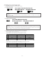
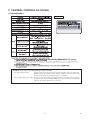
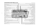
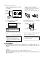
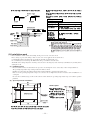
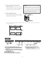
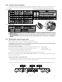
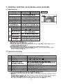
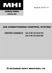
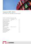
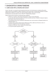
Manual No. ’08 . SC-T - 119
updated December 22 ,2009
TECHNICAL MANUAL
Collection data
AIR CONDITIONING CONTROL SYSTEM
CENTRAL CONTROL
SC-SL1N-E
SC-SL2N-E
SC-SL3N-AE
SC-SL3N-BE
CONTENTS
1. CENTRAL CONTROL SC-SL1N-E .................................................................... 2
2. CENTRAL CONTROL SC-SL2N-E .................................................................... 7
3. CENTRAL CONTROL SC-SL3N-AE, SC-SL3N-BE ........................................ 15
4. CONNECTION EXAMPLE ................................................................................ 40
■Number of units in combinations of SC-SL1N-E, SC-SL2N-E and SC-SL3N-AE, BE
(per system)
●In case of new SL (Super Link)
SC-SL3N-AE, BE
0
0
0
0
0
0
1
1
1
1
1
2
2
2
2
2
2
SC-SL2N-E
0
1
2
3
4
5∼8
1
2
3
4
5∼8
0
1
2
3
4
5∼8
SC-SL1N-E
12
8
4
0
8
4
0
8
4
0
●In case of previous SL
SC-SL3N-AE, BE
0
0
0
0
1
SC-SL2N-E
0
1
2
3
1(×3)(1)
SC-SL1N-E
6
3
2
0
0
Notes (1) In case of previous SL, since SC-SL3N is for connection of 3 Super Link systems, one unit of SC-SL2N-E can be connected to
each system.
(2) Number of units in combination as shown above is applicable to when the indoor units being controlled by each central control are
not duplicated. When controlling the same indoor units with a plural number of central controls, it may affect the allowable
number of indoor units for connection. For further details, please consult your dealr.
■Check indicator table
SL-1N-E
SL-2N-E
SL-3N-E
Error code Red LED
Keeps flashing
Indoor unit control PCB
Red LED
Green LED
Stays OFF
Keeps flashing
Outdoor unit control PCB Location of
trouble
Red LED Green LED
Description of trouble
SL-1N-E • Communication error (Defective communication circuit on the main unit of SL1N-E,
Stays OFF Keeps flashing SL-2N-E
SL-3N-E SL2N-E or SL3N-E)
-
1-
Repair method
Replacement
*
1 CENTRAL CONTROL SC-SL1N-E
(1) Specifications
*
0- 12' 0) 12)' &0(&' (+ &0(&' ( &
'% 3 4 350
,
0 #3 6 738"3 /9
,
:$
-.
/$*
3 3(7" ) %
+. " &' &
'% ;
( <= -.
) / 0> 2? 0 / )> &1),
Appearance
!" # $
% &
'% &$ #(# ) )
Definitions of new and previous Super Links (new and previous SL)
New Super Link (new SL):
All units connected to the network are models compatible new Super Link (KXE6 or
later models. Central controll and I/F are “N” or later models.), and the SL setting is
unchanged from the shipment (“New” or “Auto”).
Previous Super Link (previous SL): Units that do not meet the conditions of new SL. When the equipment connected to
the network include even one unit of model earlier than KXE4 or not with new SL.
Setting of Note (3) is required.
(2) Functions
)!
( , / & - " ! & * 0" * * + !
, +- .&* !" "
# " # $#%# &''" ( ' & (3) Outline drawing
%
%
! "
#$ "
-
2-
(4) Electrical wiring
● Please do the grounding work. Please do not connect earth line with gas pipes, water pipes, lightning rods and grounding line of
telephone.
● Please do not turn on the power supply (local switch) until all of the work is completed.
● Please wait at least two minutes after the indoor and outdoor units are turned on before turning on the power supply.
● Please be sure to build the breaker which is easily accessible with building equipment’s wiring.
● Please use the signal input device which comply with a relevant IEC safety standard.
! (a) Wiring outline
$% &'&(( " #
") $%
* +
For the relay attached with local signal input device, please use the relay whose smallest contact point (ON/OFF) current is less
than 4mA.
Caution
Please do not connect power supply line to other terminals.
Misconnection may cause damage of electrical component and burnout, which is very dangerous. Check the wiring
again before turning on the power.
(b) Wiring specifications
% $ &(##&
)3
566 & 1 ).(##& 1 &(##&
5* )))# 5* +
&
)))# 7 + )))#
# 66 %86 & 1 ).(##& 1 &(##&
5* &))#
).(##& 1 4##&
! " # $ % (5) Installation work Installation procedure & ' # ())# #*## + )))#
,- ).(##& # * )))# / # $ - 0 - $ &010 2 /$ 2//
(5) Installation work
Please install the central control after turning off the power for fear of electric shock. Please arrange or protect the wiring so that
excessive force is not applied to the electrical wires.
Be careful that you do not damage the PCBs when using a screwdriver and other tools. The PCBs can be damaged by static
electricity, and so be sure to discharge any static electricity accumulated on your body before starting the work. (Static electricity
can be discharged by touching the control board and other grounded parts.)
(a) Installation Place
Please install in an indoor location that is not exposed to electromagnetic waves, water, dust, or other foreign substances. The
operating temperature range of this product is from 0˚C to 40˚C.
Install in a location where the ambient temperature remains within the operating temperature range. However, if the operating
temperature range is exceeded, be sure to implement corrective measures such as installation of a cooling fan. Be aware that
continued usage of this central control outside the operating temperature range can result in operation problems.
-
3-
(b) Space required for installation
$ % & '
"# !
The dotted lines show the installation opening section for installation on the control board (the dimensions are only an example).
1) In case of installing on the control board
Please be sure to lock the control board to protect persons from electric shock.Avoid usage of heat-retaining materials and
heat-insulating materials because these can result in heat buildup and adversely affect the operation of the central control.
2) In case of embedding in a wall
Please check that the sufficient space is available in the wall.If the temperature inside the wall exceeds 40°C, install the
central control on the control board.
Caution
Please do not install devices that can cause the ambient temperature to rise in the same control board. Also, do not install
multiple controllers in the same control board. These can cause heat to build up and result in false operation. If multiple
central control must be installed in the same control board, take corrective measures to ensure that the temperature in the
control board does not rise above 40°C such as by installing cooling fans.
(c) Installation procedure
1) In case of embedding in a wall, first,
embed the power supply wire, signal
wire, and electrical box.
Keep the power supply wire and
signal wire separated to prevent
malfunctions.
2) Please remove the upper case with
the following procedure.
1 Remove the screw (M2.5) by
philips-head screwdriver. (Please be
careful not to lose the screw.)
2 Open it in the direction of 3
while pushing the upper part lightly.
2
2
3
!
1
Caution
Please do not install facing upward
or at a slant.
Allowed
Not allowed
Not allowed
-
4-
3) Please connect the power supply
wire.
Caution
Please confirm the voltage of
power supply, and then connect
the common or 230V correctly.
4) Please connect the grounding wire.
Connect the grounding wire for
power supply wire to “Ground 1” ,
connect the grounding wire for signal
wire to “Ground 2”.
5) Please fix the central control on
the Electrical box or the wall by
supplied 5 pan-head screw
Upper case
6) Please connect the signal wire
(A, B terminal)
Electrical box
Power supply kit
2
1
5
Pan-head screw
central control
Be careful not to
trap wires.
2 ( )
7) Please do group setting by a precise
driver (For the details, please refer
to “(6) Control switch
selection” and “(7) Setting the
control target units”).
8) Please cover the upper case onto the
lower case and attach the case by
the screw.
(Follow the reverse procedure of
(2)) round type label can be used
to cover the screw. This completes
the installation procedure. (There
are 3 round type label, 2 of which
are for standby.)
Caution
The case and power supply kit are
integrated unit. Please do not
separate them.
(6) Control switch selection
It is possible to change the setting as follows by setting switch SW23 on the printed circuit board of this central control.
Please change the control on site as necessary. It is recommended to change the setting by using a precise driver.
" (
!" #$ % $" #
)& * + ) $" (
!" #$ %
!% $ & '
" $ & ' " $% $ &(,
- $ "& !% " $ & $ # * ( ! (
-
5-
(7) Setting the control target units
For this central control, please set the unit number as follows.
(a) Setting start address
Hundreds place Tens place Ones place
Hundreds place Tens place Ones place
OFF(0)
ON
SW21
1 2 3 4
SW22
ON
SW23-1
0
0
1 2 3 4
1 2 3 4
ON
Hundreds digit Tens digit Ones digit
OFF(0)
0
5
Caution
For start address, please set from 00 to 47 for previous Super Link (SW23-3 is ON) or set from 00 to 127 for new Super
Link (SW23-3 is OFF).
(b) Setting of connection number
Tens digit Ones digit
SW20
SW19
Tens place Ones place
0
Tens place Ones place
7
1
6
Caution
One central control can connect up to 16 units. So the maximum number of connecting unit is 16. Please set the value
(Start address + number of connection unit) <
= 48 when the previous Super Link system is applied, set the value (Start
address + number of connection unit) <
128
when
new Super Link system is applied.
=
(c) When this central control controls more than 17 air conditioners
Please use multiple central control of this type.
1) It is possible to connect more than one central control in the network.
Example: Address-setting example when 6 central controls (a - f) are used
a
b
c
d
e
f
Start address
000
005
010
016
Setting value for multiple units
05
05
06
08
024
034
10
02
Number of controlled units
000-004
005-009
010-015
016-023
024-033
034-035
2) It is possible to repeat the unit number when multiple central controls are applied.
Example: Address-setting example when 3 central controls (a - c) are used
Start address
a
b
c
000
010
023
Setting value for multiple units
15
15
06
No.10 — No. 14 units can be controlled by both central control a and b.
No.23 — No. 24 units can be controlled by both central control a and c.
-
6-
Number of controlled units
000-014
010-024
023-028
2 CENTRAL CONTROL SC-SL2N-E
(1) Specification
Appearance
(
/
)
/
(Close; Center & Stop all units)
(Close; Center & Fan mode)
Definitions of new and previous Super Link (new and previous SL)
New Super Link (new SL):
All units connected to the network are models compatible with New Super Link
(KXE6 model or later models. Central controller and I/F are from “N” models.) and
SL setting is unchanged from shipment (“New” or “AUTO”).
Previous Super Link (previous SL): Units do not meet the conditions of New SL. When even a single unit connected to
the network is an earlier model than KXE4 or the connected model is not compatible
with New SL. Setting explained in *6 is required.
-
7-
*
The diagram below shows the central control with its cover open.
Also, for the sake of the explanation, all the contents of the LCD display section are shown.
REMOTE CONTROL OPERATION ENABLE / DISABLE display
Displays items for which remote controller operation is disabled.
PROGRAM SET display
Displayed when a program is being set.
TIME SET display
Displayed when the current date and time are being set.
TIME display
Displays the time.
GROUP SET display
Displayed when the units to be managed are being set.
Program days of the week display
is displayed above today’s day of the week and _ is displayed under each day of
the week for which the program has already been set.
ALL / GROUP / ONE display
Displays whether operations on this central control are for
all units, one group of units, or one unit.
GROUP No. / UNIT No. display
Displays the group number and indoor
unit number being set or monitored.
PROGRAM display
Displays the contents of the program set.
-
8-
PROGRAM No. display
Displays the numbers of the programs that have been set.
MODE display
Displays the operation mode.
DEMAND display
Displayed during demand input.
MENU button
This button selects the setting mode.
ALL / GROUP / ONE button
This button selects ALL, GROUP, or ONE to be operated.
SELECT ( or ) button
This button is primarily used for selecting the group number
or unit number.
SET button
This button conìr ms settings.
RESET button
Pressing this button during a setting operation cancels the last step
CENTER / REMOTE button
This button selects centralized control or local remote controller.
MODE button
This button selects the operation mode.
FAN SPEED button
This button adjusts the fan speed.
DEMAND SET button
This button sets the indoor unit for demand.
CENTER / REMOTE display
Displays which is in effect, the central control or the local remote controllers.
HOLIDAY SET display
Displayed when a program for holidays is set.
INVALID INPUT display
Displayed when a button input is invalid.
FAN SPEED display
Displays the fan speed.
MAINTENANCE display
Displayed when there is a managed unit requiring a check.
PROGRAM CONFIRM display
Displayed when a set program is displayed.
CHECK display
Displayed when there is a unit being managed in which an error has occurred.
CLEAN FILTER display
Displayed when there is a unit being managed
whose ìlter needs to be cleaned.
ROOM TEMPERATURE display
Displays the room temperature.
OUTDOOR UNIT No. display
Displays the outdoor unit number in the ROOM
TEMPERATURE display section.
MANAG. UNIT NUM display
Displays the number of units managed in the
SET TEMPERATURE display section.
SET TEMPERATURE display
Displays the set temperature.
LOUVER display
Displays the louver direction.
TIMER INPUT display
Displayed when an external timer is being input.
RUN button
This button runs indoor units.
STOP button
This button stops indoor units.
CHECK button
This button is for service.
During normal operation, do not press this button.
FILTER RESET button
This button resets the CLEAN FILTER display.
Press this button after cleaning the air ìlter .
TEMP ( or ) button
This button sets the temperature.
LOUVER button
This button adjusts the louver direction.
TIMER INPUT SET button
This button sets an indoor unit for which operation by external timer is enabled.
(2) Operation and setting
Operation or setting is implemented individually, in the unit of group or in a batch for air-conditioners up to 64 units or 16 groups.
0
&4 51*6
6
* 5
'
"
'
$ 3)54
) + 2
1
( 7
8
9
:
2
2
2 / ( 1 , , , 2
;
1 ( 9 < !# !"# $ 1 , 1 5+
+ ( (
1 +
( &4 51*6 , ,
(
1 ;, = 3
1 %
6 5622 < 0
( % &4 1*6 !"# $ % & % ' % (
( % ) # $
* (
+ , % -./0 , 1 / , % &/ 2 +$
, (
+ $ + $
$
+ 1
$%
13 / $
( ( , 13 /
(3) Status monitor
Status monitor may be applied in the unit of group or air-conditioner.
'
&4 51*6 0
6
* & "
5+
+ (
(
7
8
2
2
9
2 :
=
,
'
, '
, '
D)
!
*+ /
=
&4 51*6 ( @ 3/ ( , &4 51*6 ( ( ( ( ( 5+
( (
( 5+
( &4 51*6 , 5+
( (
( ( + $%
( 113 /
(
( %
6 5622 ( @
( A , (
@
, +
)
@
C
, * 0 ( ( '
, '
, '
D) '
E* C
'
E* B; A !!!! '
E* B; A :9!! D)
E
+) (
( %
+%
D) F '
F '
F '
@
, +
)
@
, '( , +
) % , 5 ( , -./7 '( >)? +
%
+ 9, : !, % ( @
9, : ! A, ! ) @
( ! , ( : 9
@
A :,9!! , '
, ( A !,!!! , '
B; -
9-
(4) Program setting
Operation program can be set in the unit of group. It is possible to register the ON/OFF time or ON time + Temperature setting at
4 times a day. Operation time can be designated in the unit of minute.
(5) Administration and control
' (
)* #! + * # , (
-. ,/(,0 (1 - !
"
#
, 7 • <4=
44>
)
!(
-+ 4=
?? (
/ (
2;3 2/3 * (
9 1 . -
(
)
4
+
, (
2,
3 2/3 *(
$
1 4
- 2,
3
1
8 9 ,9 ,9
6 '54,6 . -
1 )
(
1 + -
),
2+
9 -
%
1 -
),
2,
2+
-
8 9 ,9 6 ,9
6;; -
(
-
3
8 9 ,9 ,9
6;; ,/(
,0 ( (
1 1 1 1 *(
1 )'54,61 1 1 /4'
1 4
-(
+ 1
&
7 !%
* !% 1 , 7
*
!% 1 %)+ 01
02
03
04
05
06
07
09
10
11
12
13
14
15
(6) Outline drawing
-
10 -
(7) Installation procedure
(a) In case of embedding in a wall, first, embed the power supply
wire, signal wire, and electrical box.
Keep the power supply wire and signal wire separated to
prevent malfunctions.
Caution
(b) Open the top case by following the procedure below.
1 Grasp the indentations on the right and left sides, and
pull forward to open the cover downward.
2 Use a phillips-head screwdriver to remove the screw.
(Be careful not to lose the screw.)
3 Open the top section in the direction 4 while gently
pressing the top section.
3
3
4
4
2
1
(c) Connect the power supply wire to the terminal.
(See section (8) Electrical wiring.)
(d) Use the supplied pan-head screws to secure the central control
to the electrical box or control board.
The back of the central control
Caution
(e) Use a precision screwdriver to make the control selector
settings.
(For details, see section (10) Control switch selection.)
(f) Peel off the protective sheet on the screen of central control.
(g) Insert the top case back into its original location in the bottom
case as before, and tighten the case mounting screws [(b),
2].
This completes the installation procedure.
Caution
The case and power supply kit are an integrated unit.
Please do not separate them.
Important
Please peel off the protective sheet on the air
conditioner screen when transferring the central
control to the customer. Peel off before mounting
the top case.
(8) Electrical wiring
For safety reasons, please use the round crimping terminals with insulated sleeves for connecting all wires to the central control.
● Please do the grounding work. Please do not connect earth line with gas pipes, water pipes, lightning rods and grounding line of
telephone.
● Please do not turn on the power supply (local switch) until all of the work is completed.
● Please wait at least two minutes after the indoor and outdoor units are turned on before turning on the power supply.
● Except for the central control in the figure, all of the components are obtained at the site (wires, switches, relays, power supply,
lamps, etc.).
● Please be sure to build the breaker which is easily accessible with building equipment's wiring.
● Please be sure to use the supplied round crimping terminals when connecting wires to the power supply terminal block and
Super Link terminal block.
● Please use demand input device, emergency stop input device and external timer input device comply with a relevant IEC safety
standard.
-
11 -
3 $ !
! $ !
1 ! Wiring specifications
& ! , #$ %-
Wiring Outline
! 3
2#''/*%9'/: )';+'7<
3
3
#$ %
"
!
$
$
$
$ "
#%)%
#'
,.// %*- '()% *#%)%
. #''' !
,. 0 #'''$ 1 0 #'''22/$ 2&/ ,%*- '()% * #%)%
. %''
'()% * +%
,#- 5 ! "
,2 6
6
,%- ! !$ #)''
,
0 #'''- 7$ '()% #'''
8 $ (9) Installation work
Please install the central control after turning off the power for fear of electric shock.
Please arrange or protect the wiring so that excessive force is not applied to the electrical wires.
Control PCBs (printed circuit boards) are mounted to both the top and bottom cases.
Be careful that you do not damage the PCBs when using a screwdriver and other tools.
The PCBs can be damaged by static electricity, and so be sure to discharge any static electricity accumulated on your body before
starting the work.
(a) Installation place
Please install in an indoor location that is not exposed to electromagnetic waves, water, dust, or other foreign substances.
The operating temperature range of this product is from 0˚C to 40˚C.
Install in a location where the ambient temperature remains within the operating temperature range.
However, if the operating temperature range is exceeded, be sure to implement corrective measures such as installation of a
cooling fan.
Be aware that continued usage of this of this central control outside the operating temperature range can result in operation
problems.
(b) Space required for installation
"
%
"
%
$
Service space
!
&' ' #
(
)
#$
-
12 -
#
"
$
#
$
* $+ ,) ) ) (c) In case of installing on the control board
Please be sure to lock the control board to protect persons
from the electric shock.
Avoid usage of heat-retaining materials and heat-insulating
materials because these can result in heat buildup and
adversely affect the operation of the central control.
Caution
Please do not install devices that can cause the ambient
temperature to rise in the same control board. Also, do
not install multiple controllers in the same control board.
These can cause heat to build up and result in false
operation. If multiple central control must be installed in
the same control board, take corrective measures to ensure
that the temperature in the control board does not rise
above 40˚C such as by installing cooling fans.
(d) In case of embedding in a wall
Please check that there is sufficient space inside the wall.
If the temperature inside the wall exceeds 40˚C, install the
central control on the control board.
When performing the continued installation of multiple controllers, be sure to obtain the distance between units and service
space as shown in the figure.
System wiring
1
L1
L2/N
COM
DO1
DO2
COM
DI1
DI2
DI3
A
B
2
3
4
5
6
7
8
9
10
11
12
1 20 3 ' ## * 5#!
3 4
6#78#9:
, 4 ; 4
#
#
! " #$% ;" -
-(
/0 " &#' 0 ( )* ++ ;
-
) 4
! #' , - -
13 -
(10) Control switch selection
It is possible to change the setting as follows by settings of the PCB switches SW1 to SW10, J1, J2, and J3 on the central
control. Please change the control on site as necessary. It is recommended to change the setting by using a precise driver.
(a)
Switch
Power failure compensation function selector
Function
Power failure
compensation function
Automatic mode display
New/Prev. Super Link(*1)
Sending of data during demand input
Sending of program settings when power comes back on
(The operation status before the power failure is sent if
there is no program when power comes back on.)
Sending of operation status before power failure
(Do not make this setting.)
No data is sent when power comes back on
Time Month.Day
Return to the The units
original status have stopped
(b)
Operation after
emergency stop cancel
Jumper wires
Short circuit (default) When disconnected
Setting not possible
Center/ Remote setting (*2)
Setting
(Including during (Including the allowed/prohibited settings
possible
external input.)
of each remote control function)
J2
―
―
(Do not disconnect.)
J3
―
―
(Do not disconnect.)
1
2
3
4
5
6
7
8
9
10
,
(11) Setting the control target units
Make the settings for the units to be controlled by the central control.
For the setting procedure, see the user’s manual attached to the central contrl.
At shipping, none of the units are set as target units for control, and so the units to be controlled by this
central control must be set as control target units.
Three types of settings are available.
① Units are selected as control targets for central control and controlled as a group →Group setting
② Units are selected as control targets for central control but not grouped
→Individual setting
③ Units are not selected as control targets for central control
→Not target units for control
(or units will be controlled by another central control)
Be sure to set the current time. This is needed for the program settings and error history display.
Turn on the power and press the three buttons (MENU, RESET, GROUP No. 10) at once more than five minutes, that can
initialize the setting contents.
●
Group control when using multiple units
This central control can control up to 64 target units (up to 48 units when using the previous Super Link setting). Multiple
central controls must be installed to control 65 or more air conditioner units.
When connecting multiple central controls on a single network, any group settings can be made for each central control.
-
14 -
*
3 CENTRAL CONTROL SC-SL3N-AE and SC-SL3N-BE
(1) Specifications
"
#- E%+ #0 E0+ #*+ *%- #- E%+ #0 E0+ #*+ *,9 #*+ *%#*+ *,% +/ %
> &?#
; !
) > & $) .24 =@
; '
-< ='"
4
&
(&)
/
9< +A 9< 7 /)
; +A 9< &7 / B 9< && # +#") +#" ) . 4
+/ +A /) ; +A /
D) 7 ) 56 ) # 8 -
! ) *0
/ #A C #
)
*
56 ) # "
0 / # "
1 C #
) 9<
& % "#&$
0 % A 0) 8 ! A #
0
) 9<
& % "#&$
- % A #) 8 ! A Appearance
#*+ *%-
&
.
! "#$ %
' ! () #*+ *,-
+#" / ) / 011 % 2 . 3#
4 "! 0 51 6 ) ! 0 # 7 ! ! 089+) ! ! ) : * (2) Operation and setting
Operation and setting is implemented in group or in a batch for the maximum 128 groups (144 for previous SL).
Note (1) Operation or setting cannot be done in block.
%
$8 90):'
:
) /
3(98
( * 2
0
& ;
<
=
2
2
2 . '& 0 1 + !+ + 2
5
0 & = > ?! ?! " 0 9*
* &
0 9*
& $8 90):' + +
" &
0 5+ @ 3
0 #
: 9:22 > /
!
& ' # $8 0):' ! " # $! # % # &
& # ' ( ! "
) &
* + # ,-./ + 0!1 . + # $!. 2 *"
+ &
* " * " "
* 0
"#
03 1. 03 4. "
& & + 03 1. 03 4.
5#"+ 6133 3(7 6133 8
(7 * & 0 6!
7 6!
$7
-
15 -
Definitions of new and previous Super Links (new and previous SL)
New Super Link (new SL):
All units connected to the network are models compatible with New Super Link
(KXE6 model or later models. Central controller and I/F are from “N” models.) and
SL setting is unchanged from shipment (“New” or “AUTO”).
Previous Super Link (previous SL): Units do not meet the conditions of New SL. When even a single unit connected to
the network is an earlier model than KXE4 or the connected model is not compatible
with new SL.
Use the “Function setting” screen of main unit to set new or previous Super Link (new or previous SL).
When the connecting network consists of previous Super Link, it is necessary to change the selection.
(3) Control selection setting
It is possible to change the setting as follows by setting on the “Function Setting”
% & & & 6 (
0
' & 1 & 6 6
2 & & !
5
/
5
&
() () ,+,-. ,
/
&
&
2 ,
/
&
(
& ( /
&
"
5
/
&
& & ,- +,-.
& 0 (12 & ,
/
&
& 0 1 +3. 0 1
+3 4 . )
#
$
& ( & ) * )
+,- ).
(4) Status monitor
Status monitor can be applied in the unit of block, group or air-conditioner.
No.
Item
Description
1
RUN/STOP status
It displays ÒRUNÓ if any units are running or displays ÒSTOPÓ if all units are
stopped.
2
Operation mode
Displays the operation mode of the representative air-conditioner.
3
Temperature setting
Displays the temperature setting of the representative air-conditioner.
4
Room temperature
Displays the suction temperature of the representative air-conditioner.
5
Lock/Unlock setting of remote controller
Displays the status of permission/prohibition setting for remote controller of the
representative air-conditioner. Permission/prohibition setting for each function, as
set from the remote controller is not reflected because it is overwitten from SL3NAE (SL3N-BE).
6
Fan speed
Displays the fan speed of the representative air-conditioner.
7
Fan direction
Displays the auto swing ON/OFF setting and position setting of the representative
air-conditioner.
8
Filter sign
When the filter cleaning time is exceeded on one or more indoor units, the filter sign
icon is turned on. When it corresponds to the unit No. on display, the icon blinks.
Maintenance (*)
(Inspection, Inspection 1, Inspection 2 and
Backup)
When there is one or more indoor units requiring maintenance, the maitenance
icon is turned on. There are 4 types of operation of Inspection, Inspection 1, Inspection 2 and Backup.
Preference order of display is as shown below.
Backup > Inspection 1 > Inspection 2 > Inspection
It is possible to confirm on the ÒUNIT INFORMATIONÓ screen which maintenance has been generated.
Error
When any error is detected on one or more controlled indoor units, the error icon
is tumed on.
9
10
* When the operation time (GHP outdoor unit) exceeds 9,800 hours, it displays Inspection 2, or Inspection 1 if it exceeds 10,000 hours.
-
16 -
(5) Schedule setting
This schedule can be set by each group every one minute.
It is possible to register the RUN/STOP time, operation mode, remote controller Lock/Unlock setting, temperature setting at 16
times a day.(*)
! "
# ! $ # # # (6) Management and control
%
&
$ /
& /
/ " /
& /
/
&
0 /
&
• 12& / /
* /
3 2& / /
- &
12& / /
* &
$ 5
2& * :
0 5
> 5
0 5 5
/ & 5
2 #
$<'%5
$<'%5 &
0 5
5
%
& &
• 12& / (( 3 2& / 5
* 5
&
• 12& / * &
'
(
)
$ 5
&
$ =
#(5
/:::
: 0 &
2 '.. 5
5
& " 5
" &
*
+
$ 6 !
8 & " /
&
9 5
> 6
!
8 6;>8 > .5&
5
6C%8 6<< <
8 " 2
& B 0 D
,
/
<
:
&
$ 5
6$;!8 6<< <
5
8 " 2 & B 0
<
:
6$;!8& -
"
" /
&
678 9%:$;!0 0
<
:
0 /
"&
" 0 "
5
" & 5
678 9%:$;!0 0 <
:
0 " "&
!
" .
0 " 5
$<'%5
$<'%5 5
& =
">0 <
:
<< &
!
" #
" 5>
0 /
5
0 0 0 0 6 !
8
0 # &
?
>
0 / /
0 0 5
$ #
@ " A 6$
8 &
%
$5$<'%5
# ;
/
" &
-
17 -
(6) Outline drawing
!
" #$
"
#$
% &
● ' ( )*+,-
● . / &' - "" 0 #" &' "" (7) Installation work
Please install the central control after turning off the power for fear of electric shock.
Please arrange or protect the wiring so that excessive force is not applied to the electrical wires.
(a) Installation place
Please install in an indoor location that is not exposed to electromagnetic waves, water, dust, or other foreign substances. The
operating temperature range of this product is from 0˚C to 40˚C.
Install in a location where the ambient temperature remains within the operating temperature range. However, if the operating
temperature range is exceeded, be sure to implement corrective measures such as installation of a cooling fan. Be aware that
continued usage of this central control outside the operating temperature range can result in operation problems.
(b) Space required for installation
Please choose one of two ways.
-*. )/
-*. ))/
) * + (
,+
%&' &(
+ !"#$
1) In case of installing on the control board
• Please use the control board of the size of 300mm
x 400mm x 120mm or larger.
• Please be sure to lock the control board to protect
persons from the electric shock. Avoid usage of heatretaining materials and heat-insulating materials
because these can result in heat buildup and adversely
affect the operation of the central control.
<No partition>
!"#$
<With partition>
Internal wall
Beam of
building
Partition
a
Caution
Please do not install devices that can cause the
ambient temperature to risea in the same control
board. Also, do not install multiple controllers in
the same control board. These can cause heat to
build up and result in false operation. If multiple
central control must be installed in the same
control board, take corrective measures to ensure
that the temperature in the control board does not
rise above 40˚C such as by installing cooling fans.
more than
105mm
2) In case of embedding in a wall
Please be sure to use the special box, SLA3R-BX (sold
separately) to secure sufficient air circulation space. If
the box is unused, the central control will not work
properly because of heat buildup inside the box.
Please be sure to use for protecting persons from the
electric shock.
Please check that the sufficient space is available in
the wall.
When the inside of the wall is divided and have a cavity,
please create space more than 0.08m3. Refer to the table
below.
If there is no partition on the left, right, top and bottom
of the central control, please create a space that is
105mm or deeper.
When you cannot create the sufficient space or
thickness of the wall is above 15mm, please install the
central control on the control board.
-
SLA3R-BX
Central
control
b
80
Outline drawing of SLA3R-BX
228
132
60
4-¿6
4-M4
18 -
155
198
c
Internal
wall
153
%&' &(
+ !
!
!
(c) Installation procedure
1) Remove the upper case
a) Take out two screws using a cross slot screwdriver. (Don’t lose the screws)
b) Pull the upper case a little forward and push above. Then, upper case can be removed.
>
Caution
>
● Embed signal wire and power supply wire in a wall beforehand.
● Connect wires to the terminal block.
● Confirm power supply voltage and connect correctly.
Allowed
=
Not allowed Not allowed
Please do not install facing
upward or at a slant.
2) In case of installing on the control board
!
"
# $ %
$
&
3) In case of embedding in a wall
• Please be sure to use the special box, SLA3R-BX (sold separately).
!
"# $%&'()* !+
"# $%&'()* , +
- ! .! ,
(8) Electrical wiring
For safety reasons, please use the round crimping terminals with insulated sleeves for connecting all wires to the central control.
● Please do the grounding work. Please do not connect earth line with gas pipes, water pipes, lightning rods and grounding line of
telephone.
● Please do not turn on the power supply (local switch) until all of the work is completed.
● Please wait at least two minutes after the indoor and outdoor units are turned on before turning on the power supply.
● Except for the central control in the figure, all of the components are obtained at the site (wires, switches, relays, power supply,
lamps, etc.)
● Please be sure to build the breaker which is easily accessible with building equipment's wiring.
● Pease be sure to use the supplied round crimped terminals when connecting wires to the power supply terminal block and Super
Link terminal block.
● Before connecting the wires, remove the cover of the terminal block. After the work is completed, fix the cover of the terminal
block as before. The cover is used to prevent electric shock due to accidental contact.
● Please use a gas meter or wattmeter, demand input device and emergency stop input device which comply with a relevant IEC
safety Standard.
(a) Wiring outline
'()
, $% !$&
1
1
1
!"
# !"
5%! !!
* !!
2& $%$%!) (%!% !% ! 3
%
- 41 ""
.%$$
- #1*0
'() *")$
! )% !
! -" )% "! %!!"!
./ !0 . $% - #1*0
+"%( )% !
-
19 -
Wiring Specifications
%
&" .//" 0 &+% 0 %
.' &&& ! .' ( &&&$ 1 ( &&&
2// 23/ 0 &+% 0 %
.' ( && 2// 23/ 0 &+% 0 %
.' ( &&
&+% 0 4
# "
#! $ 1 $ $
1 ! "
#!$ %&& ! ' ( &&& )*
$ &+% ' &&& ,
$ (b) System wiring
The back of the central control
2 4 6
1 3 5
Ground
position ÒaÓ
Ground position ÒbÓ for
Super Link system signal wire
8 10 12 14 16 18 20 22 24 26 28 30 32 34 36 38
7 9 11 13 15 17 19 21 23 25 27 29 31 33 35 37 39
Terminal block
(two tiers)
1) The upper tier of terminal block (*)
L1
L2/N
2
4
DO1 D1- DO2 D2- COM
8
10
12
14
16
+ (*1)
+ (*1)
Power
Power
supply
supply
6
Power supply Please be sure to
AC100-240V use the accessory
terminals (L).
50/60Hz
(*1) Power supply : DC 24V
Maximum rating current :
40mA
DI1 COM
18
20
DI2
22
24
(*2)
(*3)
(*3)
Error
Demand signal Emergency stop
output(O2) input(I1)
signal input(I2)
Operation
output(O1)
(*2) Factory default of error output (normal operation)
is closed status.You can choose "Open" status for
malfunction output during normal operation.
A1
28
26
B1
30
A2
32
B2
34
A3
36
B3
38
Super
Link
system 3
Please be sure to
use the accessor
terminals (S).
(Same for A2, B2,
A3, B3)
Super Link system 2
Super Link system 1 (*4)
(*4) When choosing the new super
(*3) No-voltage a-contact input
Contact capacity :
link setting, only system 1,
DC12V, 10mA
(A1, B1) functions effectively.
2) The lower tier of terminal block
1
3
5
COM
7
PI1
9
COM PI2
11
13
COM
15
PI3
17
COM
19
PI4
21
COM
23
PI5 COM
25
27
PI6
29
COM
31
PI7
33
COM PI8
35
37
39
Power input from gas meter or wattmeter (8 points)
(in case of SC-SL3N-BE)
Caution
Please connect the gas meter or the wattmeter that satisfies
the specification below.
• the meter with pulse transmitter
• the meter with pulse width of 100ms or more
The energy consumption calculated by this central control
does not conform to OIML, and there are no guarantees
concerning the results of the calculations.
Caution
Do not connect power supply wire to another terminal
block.When you connect by mistake, damage and damage
by fire of the electric part are caused, and it is very
dangerous.
Please check the wiring thoroughly again before it turns
on power.
Notice
Please choose the new or previous setting of Super Link (SL) in the display of SL3N-AE (SL3N-BE). (See user's manual)
It is necessary to change if the connection network is for previous Super Link. Whether the real connection network is new Super
Link or previous Super Link depends on the type of connected indoor unit,outdoor unit,etc. Inquire the agents or dealers for more
information.
When the new Super Link setting, 1 system can connect up to a maximum of 128 units. Be sure to connect wiring to the Super
Link terminal 1 (A1, B1). Be careful not to connect to the Super Link system 2 or 3, as SL3N-AE (SL3N-BE) will not be
recognized.
-
20 -
(c) Reset switch
There is a switch to reset the power supply when the screen freezes.
Data is never deleted with this switch.
This central control will be reset in about 1 second.
Operating method
Please push the button which is the inner part of the small hole of the underside of the
upper case using the clip which is extended straight or the tool which is similar to that.
Note
Please peel off the protection sheet of the screen when you pass the central control to
the customers.Before you mount the upper case, please peel off the sheet.
¿1.5 or more
Reset switch
After checking the wiring and doing reset switch operation, when the screen is not displayed, please contact the shop where the
central control was purchased. This product consists of the exclusive parts, and you can not exchange the electrical equipment.
Please do not disassemble other than this instruction manual stating.
(d) Other information
• This central control is electronic and independently mounted control.
• The type of this central control is automatic action for which the manufacturing deviation and the drift of its operating value,
operating time or operating sequence have not been declared, and tested under the standard.
• The actions of this central control are full-disconnection on operation, a trip-free mechanism which cannot even momentarily
be reclosed against the fault, an action which can only be reset by the use of a tool, and an action that does not require any
external auxiliary energy source of electrical supply for its intended operation.
• The rated impulse voltage (impulse withstand voltage) is 2500V.
• The surface of touch panel and front cover produce an increase of temperature of about 15 degrees.
• The definitions of types of control are electrical control, automatic control, and operating control.
• The lifetime of the keying of touch panel is one million times. The lifetime of LCD is about 20,000 hours. (The brightness will
become half of the starting value.)
(9) About the accounting calculation
(a) Selection of watt-hour meter (Gas flow-meter)
To calculate the account, it is necessary to procure a watt-hour meter (gas flow-meter) at site. Select a meter according to the
following items.
(b) Selecting the pulse unit
1) Restrictions on the pulse input receiving side
100 ms
or over
Restriction on the device side
1 pulse or more/day (Desirable that it is 1 pulse/10-minute or more.)
200 ms or over
2) Selecting the pulse unit
1 Calculate the total of power supply capacity required for the air-conditioners to be connected.
2 Select provisionally an integrated wattmeter that fits to the requirement.
3 Maximum operating status of air-conditioner: Estimated overload condition expected in the summer season, for example:
If it is assumed to be the total power consumption 1.2;
Example) Provided the total power consumption status = 100 kW and the power factor = 90%
If max. operating status = 100 1.2 = 120 kW, 3-phase, 200 V
I = 120 1,000/(1.732 200 0.9) = 385A
/ The watt-hour meter needs to have a capacity of 400 A.
If we select an oscillation device from Mitsubishi’s products of 400 A:
• K11 type – Select the pulse unit 100 kWh/P or 10 kWh/P
• K12 type – Select the pulse unit 100 kWh/P or 10 kWh/P or 1 kWh/P
* For a further small pulse unit, consult a watt-hour meter manufacturer.
4 Check for when the power consumption is 120 kWh (Example)
● If 0.1 kWh/P is selected when the pulse input is the largest: 1,200 P/h = 20 P/min, which means it is 20 pulses/min, and
so this is acceptable.
● If the duty cycle decreases to 1/10 (12 kWh), for example; If 10 kWh/P is selected, 1.2 P/h = 0.02 P/min, which means
that there is no pulse within 10 minutes. It becomes 28.8 pulses for a day. If 1 kWh/P is selected, it is 12 P/h = 0.2 P/
min, which means that there are 2 pulses/10 minutes.
Since it is sufficient for the calculation if there is 1 pulse a day, it is possible to use 10 kWh/P. However, since it is likely
to produce calculation errors depending on the duty cycle, it is better to use 1 kWh/P.
-
21 -
a) Maximum count number of power pulse input
b) Maximum count number of gas pulse input
Gas volume pulse unit
0.05m3/P
0.01m3/P
3
3/day
/day
4,320m
21,600m
Maximum measurable
flow rate
180m3/h
900m3/h
0.1m3/P
43,200m3/day
1,800m3/h
0.5m3/P
216,000m3/day
9,000m3/h
If 2 m3/h is consumed at 0.05 m3/P, it is 40 pulses/h. If 10 m3/h is consumed at 0.5 m3/P, it is 20 pulses/h.
(c) Energy consumption calculation nethod
The base of calculation data is output as a file, which can be edited using one of spreadsheet software available from market, via
USB memory. The base data are created on the monthly basis.
< Calculation procedure >
1 Accumulate operation times of respective air-conditioners. (Per minute)
2 Obtain the amount of operation for each air-conditioner (Ki) and accumulate it on
the basis of time zone (within business hours, overtime hours) (Per minute)
Ki = Ki + KM
KM = : Amount of operation for air-conditioner per minute
Amount of operation is calculated with the following 3 methods. (Set the calculation method on the air-conditioner definition screen
of SC-SL3N-BE.)
Amount of operation when the value converted to the rated expansion valve aperture of air-conditioner is E:
• MULTI 1 (Refrigerant flow rate): Add a conversion value that takes into consideration the flow rate of refrigerant flowing through the
indoor unit. (∑Ej)
(Ej: Conversion value of indoor unit expansion valve aperture per minute)
• MULTI 2 (Thermostat ON/OFF): Convert the time when refrigerant is flowing through the indoor unit and add. (Thermostat ON time
E)
• RUN/STOP (Operation time): Convert the state when the remote controller is turned ON and add he value. (Operation time E)
(E: Conversion value of indoor unit capacity per minute)
* Set the same watt meter (gas meter) system at the same type.
* If it is set at MULTI 1 or MULTI 2, indoor units in the fan mode are excluded from the proportional distribution.
If you need to include the indoor units under the fan mode in the proportional distribution, set it to RUN/STOP.
* When the air-conditioning is not used in a day (Ex. Holiday), and thus there is no operating indoor unit to divide in proportion, the
portion of standby power does not match the value on the meter. It is necessary to re-calculate the accounting data using the spreadsheet
software.
• A simplified software to edit the accounting data is included in the accessories. Regarding the operating method, refer to the manual
attached to it.
• The accounting data can be output via the attached USB memory.
!
"#$% &
"#$% *
$ '(( ( )
'((
-
22 -
)"+,-$'.
1 In case of MULTI 1 setting: Conduct proportional distribution according to the results of a accumulated answer Hz. Accumulation
is not performed when the thermo is OFF or during the Fan mode operation.
Indoor unit A
Indoor unit B
Indoor unit C
25Hz
40Hz
60Hz
Total value of operating volume
(Total value of answer Hz)
Operating volume of indoor unit A = accumulated pulse counts power consumption per pulse 25/125 (25 + 40 + 60)
Operating volume of indoor unit B = accumulated pulse counts power consumption per pulse 40/125
Operating volume of indoor unit C = accumulated pulse counts power consumption per pulse 60/125
2 In case MULTI 2 setting: Conduct proportional distribution according to the Hz corresponding to the air conditioner capacity
(capacity equivalent Hz: fixed value) and thermo ON operating time.
Capacity equivalent Hz: equivalent value of answer Hz when exerting the indicated capacity of indoor unit (fixed value determined
according to capacity).
Different from 1, the fixed value is accumulated irrespective of the answer Hz. Accumulation is not performed when the thermo
is OFF and during the Fan mode operation.
Indoor unit A
Indoor unit B
Indoor unit C
30Hz
50Hz
70Hz
Total value of operating volume
(capacity equivalent Hz thermo On time)
Operating volume of indoor unit A = accumulated pulse counts power consumption per pulse 30/150 (30 + 50 + 70)
Operating volume of indoor unit B = accumulated pulse counts power consumption per pulse 50/150
Operating volume of indoor unit C = accumulated pulse counts power consumption per pulse 70/150
3 In case of RUN/STOP setting: Conduct proportional distribution according to the Hz corresponding to the air conditioner capacity
(capacity equivalent Hz: fixed value) and remote controller ON time.
Same as 2, the capacity equivalent Hz (fixed value) is accumulated according to the remote controller ON time only. Accumulation
is also performed when the thermo is OFF and during the air supply operation.
Indoor unit A
Indoor unit B
Indoor unit C
40Hz
60Hz
70Hz
Total value of operating volume
(capacity equivalent Hz remote controller ON time)
Operating volume of indoor unit A = accumulated pulse counts power consumption per pulse 40/160 (40 + 50 + 70)
Operating volume of indoor unit B = accumulated pulse counts power consumption per pulse 50/160
Operating volume of indoor unit C = accumulated pulse counts power consumption per pulse 70/160
User login
For owners the fee apportionment for multi machine air conditioners is more complicated and harder to explain to customers.
In many cases it's best to use simple explanations.
In addition, consumption for multi machines are calculated based on volume, making it easy for excessive cooling and differences
in building load to lead to discrepancies in electricity consumption. These different values are hard to explain. Therefore, it is
easier to explain how many horsepower were used for how long.
At this point, recommend [RUN/STOP] registration
Both multi machines and single machines use [RUN/STOP] registration.
Recommend that separate electricity meters be installed for single machine and multi machine systems.
Display every unit of electricity (kW) on the electricity consumption board. For example, register P280H as 28.0.
Current operational value = electricity volume time of operation, calculated according to the electricity volume ratio.
-
23 -
(d) Software overview (SC-SL3N-BE Utility)
SL3N-BE Utility calculates the amount of energy consumption with air conditioner’s running data saved by SC-SL3N-BE. The
amount of energy consumption is divided proportionally day by day according to the operating ratio of the air conditioner, and
it is calculated as the group total amount of energy consumption for every period.
1) Flow of data processing
1 =
!%
!!$ *1 2 .
(
"!* ( & &@
3 ( & &//
4 .
%
" !!
% %% "$ !%
5% 6
7!$ 8 6592 :.
! %
8
6
;< ! %
8 )
$ ($ !
!!% "$ 7
% !
:#
USB Memory
=!!% %$ !
=!!% ! %
)
$ !!%( ( ! %
> ! !!% ? 7!$ =!!% %$ ( )
=!!% ( ) !
%
% )
$ !!
%( ( !
%
> ( ) !!% ? 7!$ (Binary format)
!
" #$ % "&' $ ( !!% ) !%
! % " % % )
* $
"+' $ !) ,& ,- !
%
Conversion
(Save)
(Text format)
& ! %$ ($ !
!%
! (
+ ! %$ ( % %$ ($ ! ! !%
! %$ ( % %$ ($ ! ! !%
(
/ ! %$ ( % %$ ($ ! ! !%
(
!% %
(Save)
. !
!$ ( (
%
) . ! % *12 2
) ( !! %
% +3 !
! %$ ($ ! !%
! (
.& .-
% %$ ( % ($ !
! !%
%$ ( % %$ ($
! ! !%
(
,& ,&//
$ ( % ($ !
! !%
(
!% %
(Text format)
!(
) % ! ) ( ($ !
( ! % "! !
(
!
!$ % (
) "
!( !%
4 ($ !
(
.
( " -
24 -
2) Function outline
● Calculates and makes the monthly data file of the air conditioner’s group energy consumption in the specified period.
• The operating time and the energy (electricity and gas)consumption for each air conditioner’s group.
• The data file is saved by the CSV format. The air-conditioning charge calculation is possible by the spreadsheet software
(Microsoft® Excel, etc.).
● Imports the definition file and monthly data files that are saved by SC-SL3N-BE, and converts to CSV format.
• SL3N-BE Utility imports the group definition file and the monthly data file saved by SC-SL3N-BE via USB memory,
and converts them into the CSV format.
3) Working environment
● Operating system
Microsoft® Windows® 2000 SP3, 4
Windows® XP
Windows Vista®
● Hardware
Pentium 300 MHz or greater
128 MB RAM
5 MB free hard disk space
1 USB (1.1 or 2.0) port
● The screen size of SL3N-BE Utility is optimized by the following setup.
800 600 resolution display
Small font size
4) End user agreement
This software is for using SC-SL3N-BE. Mitsubishi Heavy Industries, Ltd. (MHI) permits you to use two or more copies of
this software on two or more computers.
This software and SC-SL3N-BE do not warrant the contents of the calculation result.
Please be sure to use a calculation result in the customer's responsibility.
MHI or its suppliers are not liable for any damages whatsoever (including but not limited to damages for loss of business
profits, business interruption, or any other pecuniary loss) which results from an inability to use this software.
Moreover, whatever the cause of failure and an obstacle, MHI cannot warrant the data saved at your memory storage (hard
disk, USB memory).
5) Installation instructions
a) Insert the CD-ROM “Air-Conditioners Management System” into your CD-ROM drive.
b) Run “setup.exe” from the CD-ROM to start the installation.
-
25 -
(e) Starting and quitting the software
1) Starting the SL3N-BE Utility
Double-click the short-cut icon displayed on Windows® desktop or select the program displayed on the Start menu. The
Main Menu screen shown in Fig.1 will appear.
Fig.1 Main Menu screen
2) Quitting SL3N-BE Utility
Click [Exit] button, or [x] button of a title bar.
-
26 -
3) Screen changes
The screen changes are shown in Fig.2.
Import
Accounting
Data File
Start
Import
Main Menu
Back
Exit
BIN to CSV
Conversion
Import
Accounting Data
File screen
Meter Group
Definition
Meter Group
Definition screen
Back
Pulse Constant
Definition
Pulse Constant
definition screen
Back
Calculate Energy
Consumption
Calculate Energy
Consumption
screen
Back
Fig.2 Screen changes and operation
-
27 -
Calculate
Proportional
division
calculation
6) Calculating energy consumption
a) Start the SL3N-BE utility
Double-click the short-cut icon displayed on Windows® desktop or select the program displayed on the Start menu. The
Main Menu screen shown in Fig.3 will appear.
Step 1: Click [Import Accounting Data File] button on this screen.
Step 2: Click [Meter Group Definition] button on this screen.
Step 3: Click [Pulse Constant Definition] button on this screen.
Step 4: Click [Calculate Energy Consumption] button on this screen.
Since SL3N-BE Utility memorizes the last setting of Meter Group Definition and Pulse Constant Definition, as long as
there is no change in a setup, you may skip Step2 and Step3. However, we recommend that you check the contents of the
setting whenever you calculate.
When you manage two or more SC-SL3N-BEs, don't skip Step2 and STEP3. You need to read (“Open”) the setting of
each SC-SL3N-BE’s setteings in Step2 and Step3.
Fig.3 Main Menu screen
[Import Accounting Data File]: switches to the Import Accounting Data File screen.
[Meter Group Definition]: switches to the Meter Group Definition screen.
[Pulse Constant Definition]: switches to the Pulse Constant Definition.
[Calculate Energy Consumption]: switches to the Calculate Energy Consumption screen.
[Exit]: SL3N-BE Utility finish and this screen close.
-
28 -
Step 1: Import Accounting Data File
(1) Beforehand, export monthly data files to a USB memory by SC-SL3N-BE.
(2) Insert the USB memory in your personal computer.
(3) Click a check box. Select the drive name of a USB memory, and the folder name, which exported monthly data files.
(4) Specify the year and the month to calculate.
(5) Click [Import] button. Reading out files will start.
(6) Confirm the success of reading out files. Then, click [Back] button.
Fig.4 Import Accounting Data File screen
[Import]: Imports the group definition file and the monthly data files.
[Back]: Returns to the Main Menu screen.
● Selecting the configuration (Group definition) file.
Select the drive name of a USB memory as shown in Fig.5, and choose the file “SL3Nconfig.bin” (New Super Link) or
“SLA3config.bin” (Previous Super Link).
Fig.5 Select Group Definition File dialog box
-
29 -
● Importing Accounting Data Files
SL3N-BE Utility reads a group definition file and the monthly data file of the month specified to the "year" and the
"month", and the previous month, and converts them into the CSV files.
The converted CSV files are the following.
a) Group definition file (file name: Grp.csv)
Group name, group composition
b) Monthly data files
b-1: Daily operating time (minutes), calculated value of the air conditioner for each period (the basis period and the
overtime), in the Super Link system.
• File name (in case of New Super Link system):
SL3N1costYYMM.csv, SL3N2costYYMM.csv SL3N3costYYMM.csv, SL3N4costYYMM.csv
• File name (in case of previous Super Link system):
SL1SLA3costYYMM.csv, SL2SLA3costYYMM.csv
SL3SLA3costYYMM.csv
b-2: Daily cumulative pulses from meters (PI1-PI8) for each period.
• File name (in case of New Super Link system):
PLSSL3NcostYYMM.csv
• File name (in case of previous Super Link system):
PLSSLA3costYYMM.csv
These files are saved in the name of “DB” folder that installed the program “SL3N-BE Utility”. If you have not changed
the folder of the installation folder, the above files are placed into “C:/SL3NBEUtility/DB”.
YYMM means the year and the month.
Since the capacity of a hard disk will be insufficient, please delete the above-mentioned file once in a year.
-
30 -
Step 2: Set the Meter Group Definition
SL3N-BE Utility memorizes the Meter Group Definition last time, and reads it when starting. You may skip this menu, as
long as there is no change.
Meter Group Definition defines to which energy system (electricity or gas) the air conditioner belongs.
It is possible to assign two or more meter numbers to one air conditioner's indoor unit. It is applicable to an air-conditioning
system like a GHP (Gas Heat Pump) system that consumes different energy. It can apply, when measuring an outdoor unit
and each indoor unit with another watt-hour meter. In this case, assign meter number of an outdoor unit to indoor units.
In case of the previous Super Link system, “Unit No.” shows the “Super Link” communication line number (1 - 3) and the
indoor unit number (00-47).
Input the meter number (1 - 8) without a space into “Meter No.” column.
Fig.6 Meter Group Definition screen
[New]: Push this button when you make a new definition file.
[Open]: Push this button when the definition file already exists.
[Save]: Push this button when you want to save the current setting.
[Prev]: returns to the previous SL page. Three pages of SL1 - 3 exist in this screen.
[Next]: returns to the next SL page.
[Back]: returns to the Main Menu screen.
Caution
Setting of this screen is important when carrying out distribution calculation of the appropriate energy consumption.
It is necessary to tie in setting with an actual installation situation. Please ask your installation contractor about setting.
-
31 -
● First time
(1) Click [New] button and input the Meter number.
(2) Click [Save] button and input the file name.
(3) Click [Back] button.
● 2nd hereafter
You don’t have to select this menu. However, we recommend that you check the contents of the setting whenever you
calculate.
● If you manage two or more SC-SL3N-BEs
(1) Click [Open] button, select the definition file and check the settings.
(2) Click [Back] button.
1. Opening the definition file
When you click [Open] button, Fig.7 dialog will appear. Choose the file saved beforehand.
Fig.7 Select the definition file dialog box
2. Saving the definition file
When you click [Save] button, Fig.8 dialog will appear. Input the file name that is easy to discriminate, and click
[Save] button.
Fig.8 Save the definition file dialog box
-
32 -
Step 3: Set the Pulse Constant Definition
SL3N-BE Utility memorizes the Pulse Constant Definition last time, and reads it when starting. You may skip this menu,
as long as there is no change.
Pulse Constant Definition defines a pulse constant and the energy type (electricity or gas) for every meter.
Fig.9 Pulse Constant Definition screen
[New]: Push this button when you make a new definition file.
[Open]: Push this button when the definition file already exists.
[Save]: Push this button when you want to save the current setting.
[Back]: returns to the Main Menu screen.
● Caution
Setting of this screen is important when carrying out distribution calculation of the appropriate energy consumption. It
is necessary to tie in setting with an actual installation situation. Please ask your installation contractor about setting.
● First time
(1) Click [New] button and input the pulse constant.
(2) Click [Save] button and input the file name.
(3) Click [Back] button.
● 2nd hereafter
You don’t have to select this menu. However, we recommend that you check the contents of the setting whenever you
calculate.
● If you manage two or more SC-SL3N-BEs
(1) Click [Open] button, select the definition file and check the settings.
(2) Click [Back] button.
The input range of the pulse constant
Range
Lower limit
Upper limit
Electricity
0.00
300.00 kWh/ pulse
Gas
0.00
10.00 m3/ pulse
-
33 -
Step 4: Calculate Energy Consumption
SL3N-BE Utility carries out proportional division calculation based on the Monthly Data Files that imported, the Meter
Group Definition and the Pulse Constant Definition. And it calculates the energy consumption for every group.
Fig.10 Calculate Energy Consumption screen
[Calculate]: calculates the energy consumption.
[Back]: returns to the Main Menu screen.
(1) Specify the period to calculate.
(2) Specify the name of the energy consumption data file and the folder name.
• The folder name and file name can be changed.
• Please specify both of file names to calculate only gas or electricity.
(3) Click [Calculate] button.
(4) Click [Back] button.
1. When you click the check box “The gas energy consumption”, Fig.11 dialog box will appear. If you want to change the
file name, the folder name and the drive name, select another drive name and the folder name, and type another file
name that you want.
Fig.11 Input the file name dialog box
-
34 -
2. When you click the check box “The electric energy consumption”, Fig.12 dialog box will appear. If you want to change
the file name, the folder name and the drive name, select another drive name and the folder, and type another file name
that you want.
Fig.12 Input the file name dialog box
3. SL3N-BE Utility makes the following files as a calculation result.
1 The energy consumption in basis period every Meter number:
• File name: P1ICONSUMYYMM.csv, P2ICONSUMYYMM.csv,
…, P8ICONSUMYYMM.csv
2 The energy consumption in overtime period every Meter number:
• File name: P1OCONSUMYYMM.csv, P2OCONSUMYYMM.csv,
…, P8OCONSUMYYMM.csv
3 The running time and energy consumption every indoor unit:
• File name (in case of New Super Link system):
SL3N1CONSUMYYMM.csv, SL3N2CONSUMYYMM.csv,
SL3N3CONSUMYYMM.csv, SL3N4CONSUMYYMM.csv
• File name (in case of previous Super Link system):
SL1CONSUMYYMM.csv, SL2CONSUMYYMM.csv,
SL3CONSUMYYMM.csv <Note 1>
4 The running time and energy (electricity and gas) consumption for every group:
• File name (in case of New Super Link system):
NGRP1CONSUMYYMM.csv, NGRP2CONSUMYYMM.csv,
NGRP3CONSUMYYMM.csv, NGRP4CONSUMYYMM.csv
• File name (in case of previous Super Link system):
GRPCONSUMYYMM.csv <Note 1>
5 The Monthly Energy Consumption file:
• Default file name (you can change): MonthGYYMM.csv, MonthEYYMM.csv
These files are saved in the name of “DB” folder that installed the program “SL3N-BE utility”. If you have not changed
the folder of the installation folder, the above files are placed into “C:/SL3NBEUtility/DB”.
YYMM means the year and the month.
Since the capacity of a hard disk will be insufficient, please delete the above-mentioned file once in a year.
<Note 1>
When using Microsoft® Excel, it needs to divide and read out the file, since there is the restriction of a maximum of 256
columns. Refer to Appendix 2.
-
35 -
Appendix 1. The image of the Monthly Energy Consumption file
*** C:¥Program Files¥SLB3EUtility¥db¥MonthE0503. csv (02/05 - 03/14)
Group No
1
2
3
4
5
6
7
8
9
10
11
12
13
14
15
16
17
18
19
20
21
22
23
24
25
26
27
28
29
30
31
32
33
34
35
36
37
38
39
40
41
42
43
44
45
46
47
48
49
50
51
52
53
54
55
56
57
58
59
Group Name
1F ENTRANCE GATE
1F ENT. HALL STH
1F ENT. HALL NRTH
1F ENT. HALL EST
2F ENTRANCE ELV.
2F PASSAGE NORTH
2F PASSAGE SOUTH
3F ENTRANCE ELV.
3F PASSAGE NORTH
3F PASSAGE SOUTH
4F ENTRANCE ELV.
4F PASSAGE NORTH
4F PASSAGE SOUTH
5F ENTRANCE ELV.
5F PASSAGE NORTH
5F PASSAGE SOUTH
6F ENTRANCE ELV.
6F PASSAGE NORTH
6F PASSAGE SOUTH
7F EMTRANCE ELV.
7F PASSAGE NORTH
7F PASSAGE SOUTH
8F ENTRANCE ELV.
8F PASSAGE NORTH
8F PASSAGE SOUTH
MHIE OFFlCE #1
MHIE OFFlCE #2
MHIE OFFlCE #3
MHIE CONF. ROOM 1
MHIE CONF. ROOM 2
MHIE CONF. ROOM 3
MHlS OFFICE #1
MHlS OFFICE #2
MEE OFFICE #1
MEE OFFICE #2
MEE OFFICE #3
MEE OFFICE #4
MCFE OFFICE #1
MCFE OFFICE #2
MLP-UK OFFICE #1
MLP-UK OFFICE #2
MLP-UK OFFICE #3
MLP-UK OFFICE #4
MC OFFICE #1
MC OFFICE #2
MC OFFICE #3
MC OFFICE #4
MC CONF. ROOM 701
MC CONF. ROOM 702
MC CONF. ROOM 703
MC CONF. ROOM 710
MC CONF. ROOM 711
unused
unused
unused
unused
uhused
unused
unused
Basic Period [H]
0.0
0.0
0.0
870.0
31.7
650.8
1057.4
287.1
806.7
388.2
3.2
484.2
485.4
133.2
169.3
434.6
0.0
623.4
647.5
211.5
535.8
615.0
0.0
462.1
462.1
171.0
490.0
7.7
267.8
267.9
0.1
0.4
219.3
438.4
437.3
218.7
124.5
0.0
0.0
0.0
0.0
0.0
0.0
0.0
0.0
0.0
0.0
0.0
0.0
0.0
0.0
0.0
-
36 -
Overtime [H]
0.0
0.0
0.0
0.0
0.0
0.0
0.0
0.0
0.0
0.0
0.0
0.0
0.0
0.0
0.0
0.0
0.0
0.0
0.0
0.0
0.0
0.0
0.0
0.0
0.0
0.0
0.0
0.0
0.0
0.0
0.0
0.0
0.0
0.0
0.0
0.0
0.0
0.0
0.0
0.0
0.0
0.0
0.0
0.0
0.0
0.0
0.0
0.0
0.0
0.0
0.0
0.0
Basic Period [kWh]
0.000
0.000
0.000
1595.992
65.959
1119.757
1657.156
471.401
1226.261
654.044
5.689
868.573
1124.734
326.014
325.835
874.511
0.000
1129.392
1100.648
322.490
809.279
1124.523
0.000
710.040
710.040
293.380
1012.432
11.402
458.081
458.081
0.000
0.000
3.681
7.362
6.248
3.124
173.841
0.000
0.000
0.000
0.000
0.000
0.000
0.000
0.000
0.000
0.000
0.000
0.000
0.000
0.000
0.000
Overtime [H]
0.000
0.000
0.000
0.000
0.000
0.000
0.000
0.000
0.000
0.000
0.000
0.000
0.000
0.000
0.000
0.000
0.000
0.000
0.000
0.000
0.000
0.000
0.000
0.000
0.000
0.000
0.000
0.000
0.000
0.000
0.000
0.000
0.000
0.000
0.000
0.000
0.000
0.000
0.000
0.000
0.000
0.000
0.000
0.000
0.000
0.000
0.000
0.000
0.000
0.000
0.000
0.000
Appendix 2. Dividing and Reading out the CSV file using Microsoft® Excel
1) Open a new file and move a cursor to the position where you want to locate.
2) Choose the “Import External Data” menu and the “Import Data…” menu in the menu bar.
-
37 -
3) Select “All Files (*.*)” in the the “Files of type” and choose the CSV file which you want to read. Click the “Open” button.
4) Select the “Delimited” option button and the file format “Western European” in the “File origin” drop-down, and click [Next
>] button.
5) Select “Comma” in the “Delimiters” section of the dialog box, and click [Next >] button.
-
38 -
6) Click the head column to exclude under the “Data preview”.
7) Click the last column to exclude, pressing [Shift] key (on keyboard), under the “Data preview”. Click the "Do not import
column (skip)" in the “Column data format”, and click [Finish] button.
8) Click [OK] button. The data in the CSV file will be imported to Excel sheet.
-
39 -
4 CONNECTION EXAMPLE
Example 1: One unit of central control SC-SL1N-E can control the start/stop of indoor units up to 16 units individually
or simultaneously. It is necessary, however, to use the remote controller together.
Outdoor unit
Indoor unit
SC-SL1N-E
Remote controller
Example 2: Plural number of SC-SL1N-E can be used on a network. (This allows controlling on the basis of each floor
in an office building, for example.)
Outdoor unit
SC-SL1N-E
Indoor unit
Remote controller
SC-SL1N-E
Indoor unit
Remote controller
SC-SL1N-E
Indoor unit
Remote controller
Example 3: Central control SC-SL1N-E may be started/stopped externally using an external timer or the like. All indoor
units subject to the control are started or stopped at the same hour.
Outdoor unit
Indoor unit
SC-SL1N-E
external timer
Remote controller
-
40 -
Example 4: One unit of central control SC-SL2N-E can control the indoor units up to 64 units with the individual,
group, simultaneous RUN/STOP, temperature setting, air-flow volume setting, or other controls. Setting can
be made up to 16 groups.
Note (1) Part or whole remote controllers may be abbreviated.
Outdoor unit
Indoor unit
Remote controller
01
02
03
04
05
06
07
08
09
10
11
12
13
14
15
16
SC-SL2N-E
Example 5: Plural number of SC-SL2N-E may be connected to a network (indoor units up to 128 units). Since it is
possible to use mixed with SC-SL1N-E, SC-SL2N-E may be used for the central control and SC-SL1N-E
for the RUN/STOP at each floor.
Note (1) Number of units allowed for mixing is as shown below.
Outdoor unit
SC-SL1N-E
Indoor unit
Remote controller
SC-SL1N-E
SC-SL1N-E
01
02
03
04
05
06
07
08
09
10
11
12
13
14
15
16
SC-SL2N-E
-
41 -
"# $% !
)* # &!
)* ' # # (!
- , . 0 / 1 2 /
-
42 -
AIR CONDITIONING CONTROL SYSTEM
! "## $%
&' ( )"*+ ,-
updated 12,March,2009