1
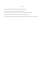
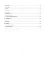
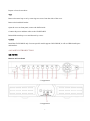
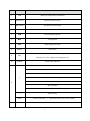
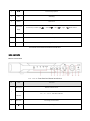
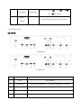
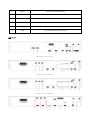
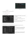
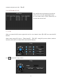
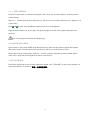
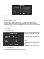
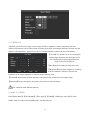
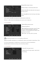
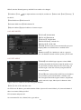
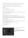
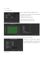
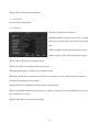
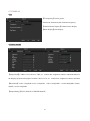
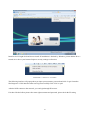
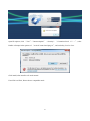
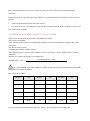
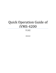
Embedded NVR User Manual V2.0 2014.1 1. PRECAUTIONS Please observe the following precautions, in order to avoid damage or loss of data caused by improper operation. NVR should work on proper temperature and humidity. Do not install NVR in humid, dusty or smoky environment. Require a solid mounting surface for installation. Do not block any ventilation openings. Install under the manufacturer's instructions. Do not spill liquid of any kind on device. Do not put any other equipment on device. Do not dismantle the device. Select specified HDD by manufacture. 1 2. NOTE This user manual is for reference only, subject to available products. This user manual may contain inaccurate data or printing error. Updates to the manual or products themselves will occur without further notification. All pictures not from the same machine, showing illustrative purposes only. Contact the customer service department when you have any question or want newest software and file. 2 Content 1. PRECAUTIONS ............................................................................................................................................ 1 2. NOTE .......................................................................................................................................................... 2 3. PRODUCT INTRODUCTION ......................................................................................................................... 5 3.1. SUMMARY .......................................................................................................................................... 5 3.2. FEATURES ........................................................................................................................................... 5 4 INSTALLATION............................................................................................................................................. 6 4.4 PANEL INTRODUCTION ............................................................................................................................ 7 4.5 REAR PANEL ........................................................................................................................................... 13 4.6 Alarm ..................................................................................................................................................... 16 4.7 POE Connection ..................................................................................................................................... 18 5 PERATION GUIDE .......................................................................................................................................... 20 5.1 POWER ON/OFFo ................................................................................................................................... 20 5.2 MOUSE................................................................................................................................................... 21 5.3 INPUT METHOD ..................................................................................................................................... 22 5.4 REMOTE CONTROL ................................................................................................................................ 23 5.5 ICON ....................................................................................................................................................... 26 5.6 LIVE VIEW............................................................................................................................................... 27 5.7 Channel MODE ...................................................................................................................................... 28 5.8 IP camera MANAGE ............................................................................................................................... 29 5.9 PTZ ....................................................................................................................................................... 30 5.10 PLAYBACK ............................................................................................................................................ 31 5.11 RECORD................................................................................................................................................ 33 5.12 ALARM ................................................................................................................................................. 34 5.13 DISPLAY ................................................................................................................................................ 35 5.14 MY E-Video .......................................................................................................................................... 35 6 OPERATION ................................................................................................................................................... 36 6.1 MAIN MENU INTRODUCTION ................................................................................................................ 36 6.2 VIDEO ..................................................................................................................................................... 36 3 6.3 RECORD.................................................................................................................................................. 38 6.4 NETWORK .............................................................................................................................................. 39 6.5 P/T/Z ...................................................................................................................................................... 41 6.6 ALARM ................................................................................................................................................... 42 6.7 SYSTEM .................................................................................................................................................. 44 7 WEB & CLIENT............................................................................................................................................ 51 7.1 WEB OPERATION ................................................................................................................................... 51 7.2 CLIENT SOFTWARE OPERATION............................................................................................................. 56 8 SMART MOBILE.......................................................................................................................................... 56 8.1 iphone .................................................................................................................................................... 56 8.2 Android .................................................................................................................................................. 58 9 APPENDIX................................................................................................................................................... 61 9.1 EXTENDED FUCTION .............................................................................................................................. 61 9.2 Common Faults ...................................................................................................................................... 64 9.3 Reference of HDD Capacity Calculation ................................................................................................ 66 4 3. PRODUCT INTRODUCTION 3.1. SUMMARY Our Embedded Digital Video Recorder is an excellent digital surveillance product which adopts H.264 video compression, hard disk recording, TCP/IP transmission, and a Linux based OS in addition to some of the more advanced technologies in the information technology industry. This enables a more stable, reliable and high picture quality. These products support synchronized video and audio recording, playback, and monitoring. This series also supports network based system control, as well as excellent network streaming capabilities. 3.2. FEATURES LIVE VIEW CVBS interface, TV, VGA/HDMI synchronous output. DECODING PROCESSING FUNCTIONS H.264 video compression, G.711 audio decording compression, Supports up to 1080P resolution decoding . RECORDING Recording modes include manual, time, alarm, motion detection, etc.; Support SATA HDD and local disk S.M.A.R.T. technology, Support USB backup and internet backup. PLAYBACK Playback search by various conditions, local and network playback; support multiple channel simultaneous playback , support fast, slow, rewind and frame mode; support exact time playback. CMERA CONTROL AND ALRM Remote camera control, Multi-channel alarm input interface for connecting various types alarm equipment; Motion detection alarm, video loss alarm, masking alarm; Multi-channel alarm output, alarm linkage and on-site lighting control. COMMUNICATION INTERFACE USB 2.0 high speed interface connecting various backup devices; Standard Ethernet interface, work under various networks. NETWORK PROTOCAL 5 Support TCP / IP, UDP, RTP / RTSP, DHCP, PPPoE, DDNS, NTP etc.; support network real-time live view, recording, playback, control; built-in WEB Server, IE browser for direct access. OPERATION MODE Support the front panel, remote controls, mouse and so on many kinds of operating mode; With simple, intuitive graphical; With simple, intuitive graphical interface. 4. INSTALLATION 4.1. CHECK NVR AND ACCESSORIES Please carefully check the contents as packing list. If any of the items are missing, please contact with your dealer. 4.2. HDD INSTALLATION Preparation Prepare a Cross Screwdriver. Note: HDD quantity by each model’s specifications shall be final, HDD capacity up to 64 TB. Steps Remove the metal top cover by removing two screws from the sides of the cover. Place the hard disks on a flat table and fasten it by screws. Connect the power and data cables to the HDD. Reinstall the metal top cover and fasten it by screws. Caution Only use HDD specified by the manufacturer. HDD will be formatted automatically during startup, it may cause data loss. Recording duration is decided by HDD capability and NVR parameters (recording setup, encoding setup). Please see the form in chapter 9.3. 4.3. CD/DVD-RW INSTALLATION Preparation 6 Prepare a Cross Screwdriver. Steps Remove the metal top cover by removing two screws from the sides of the cover. Remove the hard disk bracket. Open the cover on front panel, remove the baffle inside. Connect the power and data cables to the CD/DVD-RW. Reinstall the metal top cover and fasten it by screws. Caution Install the CD/DVD-RW only for some specific model support CD/DVD-RW, it will use HDD install space and interface. 4.4 PANEL INTRODUCTION 4CH POE-NVR Buttons on Front Panel 31 Appearance 34 Appearance 7 NO. TYPE FUNCTION 1 USB Mouse or storage device connected 2 IR receiver Remote control receiver 3 REC/STOP Recording control buttons 4 Play 5 Fast backward playback 6 Fast playback 7 ■/ Playback/play by frame 8 MENU Main menu 9 ESC Return to the previous menu, or cancel operation; Return to live view window from playback state 10 POWER Power status indicator Direction key to choose up and down Activate a drop-down menu to choose options Control addition/subtraction number ↑↓ Change check box setting Control character input 11 Move channel Control up and down when PTZ setting 12 ←→ Direction key Enter 1.Confirm operation;2.Open main menu in live view window POWER Power On/Off system 8 Status Rec, Net, Alarm, HDD status indicator 13 indicator NVR Series 8Ch NVR Buttons on Front Panel 8CH NVR NO. 1 Front Panel and button introduction TYPE Function IR receiver Remote control receiver Status Rec、Net、Alarm、Hdd Status indicator indicator 2 REC/STOP Recording control buttons 3 Playback/play 4 ■/ Playback/play by frame 5 Slowly playback 6 LOCK Lock System 7 Fast backward playback 8 PTZ PTZ Controler 9 9 Fast forward playback 10 ESC Exit key 11 MENU Main menu Direction direction key include: up【 】、down【 】、left【 】、right 【 keys Enter Confirm operation 13 POWER Power On/Off system 14 USB Mouse or storage device connected 8CH NVR Front Panel and button introduction 16CH、32CH NVR Buttons on Front Panel 16CH、32CH NVR NO. 1 Front Panel and button introduction TYPE FUNCTION IR receiver Remote control receiver Status Rec、Net、Alarm、Hdd Status indicator indicator 2 REC/STOP Recording control buttons 3 Playback/play 10 】four buttons. 4 ■/ Playback/play by frame 5 ▏ Slowly playback 6 Fast backward playback 7 ESC Exit key 8 Fast forward playback 9 MENU Main menu Control direction key include: up【 】、down【 】、left【 】、right 【 button Enter Confirm operation 11 POWER Power On/Off system 12 USB Mouse or storage device connected 32CH NVR Front Panel and button introduction NO. TYPE NAME FUNCTION 1 POWER POWER Power On/Off system 11 】four buttons. 2 CHANNEL 1-16 Select channel 3 Log off Lock Log off the user logged in 4 Multi-Video 田 Multiple Video switch HDD1-8 Lit means hard disk is recording POWER Power indicator REC Record indicator LINK Network indicator ALARM Alarm indicator HDD FULL Hard disk full indicator REC/STOP Enable/disable manual record 5 Status lamp Playback fast forward/fast backward FN Display/hide playback toolbar Playback/play 6 Function key Playback pause/play frame by frame ESC Exit key Slow play at playback MENU System main menu PTZ Initiate PTZ control interface 12 direction key include: up【 7 Control keys 】、down【 】、left【 】、 Direction keys right 【 】four buttons. Remote 8 IR Receive the signal sent by remote control control 4.5 REAR PANEL 4CH POE-NVR 31 Appearance 34 Appearance NO. TYPE FUNCTION 1 VGA VGA interface 2 VIDEO OUT Video output connecting TV or monitor, standard BNC connector 3 HDMI High definition interface 4 A-Out Audio output 5 A-In Audio input 13 6 RS485 RS 485 for connecting PTZ 7 POWER DC 13V-15V POWER IN 8 ON/OFF Power switch 9 NET RJ-45 Network interface 10 POE SWITCH 4CH POE POWER RJ-45 11 USB Used to connect mouse or back up NVR Series 8CH back board interface 16CH back board interface 32CH back board interface 14 8CH(POE)back board interface NO. TYPE FUNCTION 1 AUDIO OUT Audio output 2 VIDEO OUT Video output connecting TV or monitor, standard BNC connector 3 HDMI High definition interface 4 VGA VGA interface 5 LAN/ USB 6 ALARM IN/OUT 7 DC+12V IN 8 ON/OFF Power switch 10 POE POWER DC 48V POWER IN 11 POE SWITCH 4CH POE POWER RJ-45 12 RS485 Network interface/ Used to connect mouse or back up Alarm on-off input/ Alarm relay output DC 12V/3.42A RS 485 for connecting PTZ HVR Series 4CH back board interface 15 16CH back board interface NO TYPE FUNCTION 1 Video In For connecting analog video signal input (BNC) 2 Audio in For connecting audio signal 3 V-out 4 HDMI High definition interface 5 VGA VGA interface 6 LAN、USB 7 POWER 8 ALARM IN/OUT 9 RS485 10 ON/OFF One video output for connecting TV or monitor (BNC) Network interface/ Used to connect mouse or back up POWER IN Alarm on-off input/ Alarm relay output RS 485 for connecting PTZ Power switch 4.6 ALARM NVR series 1 2 3 1 4 NO C A B 3 4 2 4CH I/O INTERFACE 16 8CH I/O INTERFACE 16CH I/O INTERFACE Rare Panel: Index Name Description 1 Alarm input Connection for external Alarm Peripherals(PIR Sensor, Alarm Panel). 2 GND Grounding. 3 Alarm output Connection for external devices (Pezos, buzzer, siren). 4 RS-485 Communication terminal for Pan/Tilt/Zoom cameras. NVR I/O DESCRIPTION Alarm Input Connection 17 The alarm input is the switch quantity input. If the alarm input signal is not switch quantity signal but voltage signal, refer to the following connection. . Alarm Output Connection When the alarm output connect with DC and AC load, please refer to the connection POE-NVR Kits not support alarm input and output. 4.7 POE CONNECTION Step 1: Supply the NVR with the 12V DC power. Step 2: Connect the POE module with 48V directly power. Note: 48V voltage is not safe, please pay attention to the use of electricity. Step 3: The side of the network cable is connected to the POE network interface and the other side is connected to the network camera. The distance of POE power i s not more than 100 m theoretically. POE power connection 18 Step 1: Connect the power input, please use the DC13V-15V power cord with the device. Step 2: Connect the network cable between NVR POE interface and IP camera network interface (The IP camera support POE function). The POE network cable less than 100m. 19 5 PERATION GUIDE 5.1 POWER ON/OFFO 5.1.1 POWER ON NVR installed correctly, switch on with power light is on, NVR will boot up automatically. Different model have different boot up status, please refer to the Front-panel Introduction. NVR will detect the hardware when power on, the process will last 30 seconds more or less. After the detection, NVR make a ―Buzzing‖ sound and enter into a multi-screen live view, user can operate now. 5.1.2 POWER OFF Hold down on-off key to turn off device. 【Main Menu】→【Power off】→【Power off】. DIAGRAM 5-1 TURN OFF DEVICE Note: turn off device and switch off power when changing HDD. 5.1.3 OUTAGE RECOVERY 20 Reboot after an outage or forceful shutdown, NVR will save the record before outage and return to normal operation mode. 5.2 MOUSE In addition to front panel keys and remote control menu, the user can use mouse for menu functions. Insert mouse with USB interface into machine panel. Click Left Button If the user does not log in, password box will pop up first; click the left mouse button to enter the main menu when real-time monitoring. Left click mouse the Options icon enter the menu. Exact Instructions on control Change the state of check box and dynamic detection block. Click the combo box drop-down list will pop up. Under 3D PTZ control mode, click the mouse and drag to lower right can achieve 3D PTZ control .drag from lower right to up left, make 3D PTZ control narrow, details refer to 4.1.2 PTZ. Double Click Left Button Select and confirm or open, for example, double-click playback video. Under multi-screen double click one channel can make the picture full screen; double-click again to return to the previous multi-screen. Click Right Button Pop-up context menu under monitor screen Exit without saving under menu interface. Turning Wheel Increase or decrease value when fill digital box Switch combo box options. Flip up and down for list box. Achieve PTZ 3D zoom function. Mouse Move Select controls in current coordinates to move. Mouse Drag Select motion detection area. 21 Set up regional coverage area. Select 3D PTZ zoom function. 5.3 INPUT METHOD In the input box, choose numbers, symbols, case in English input. Click left mouse button to select value; ←means backspace, _ means a space. Letter Input Interface DIAGRAM 5-2 LETTER INPUT INTERFACE Number Input Interface DIAGRAM 5-3 NUMBER INPUT INTERFACE Special Symbols Input Interface DIAGRAM 5-4.SPECIAL SYMBOLS INPUT INTERFACE Chinese Input Interface DIAGRAM 5-5.CHINESE INPUT INTERFACES. 22 5.4 REMOTE CONTROL NVR remote control schematic diagram is as follows (the default is not equipped with remote control, need to customize) Diagram 5-6 Name Icon Switch the screen Mult 23 Function Switch the screen Specify the remote control address Add Specify the remote control address 1.Enter number(Digital input state) Number keys 0~9 2.Enter text ( Text input state) 3.Switch screen (single-screen state) Pause the screen round Pause the screen round (screen round state) Digital switching key Enter the number above 10: press 10 at first, then press this key and the unit digit key Record -/-- Record 1. Bring up the video control menu in real-time monitoring state; 2. Enter the preset point setting in PTZ control menu 1. Bring up the function menu in single-scr een monitoring state (PTZ control, image color) 2. Set the screen region as dynamic detection with arrow keys Fn Fn 3. Backspace function: delete a character before the caret in i nput state (it’s for input method switching if there’s no shift key on the front panel), press 1.5s to clear all the characters 4. Switch the full-screen in playback state 1. Enter operation; Enter Menu/Menu 2. Skip to <OK> option; 3. Bring up the main menu in 24 real-time monitoring state ESC Esc Exit to the previous menu 1. PTZ direction control; 2. Change numbers in digital input box; 3. Change selection states in selection box; / 4. Forward space and backspace in text input box; 5. Move the slider in slider control box; Direction keys 6. Select the last and next channel in playback window; 7. Switch the screen in real-time view state 1. PTZ direction control; / 2. Switch the currently active control; 3. Switch channels in real-time monitoring state 1. play the last paragraph video; Play the last paragraph / aperture - 2. PTZ control: aperture1. Play the next paragraph video; Play the next paragraph / iris + 2. PTZ control: aperture+ Fast forward 5 s video playback fast forward 5s Back 5 s video playback back 5s Slow play Control the speed of video playback show play Fast forward Control the speed of video playback fast forward 25 Stop ■ Stop the video 1.Play when the video playback 2.Play when the video paused Play / Pause Bring up the video query menu in real-time monitoring state The procedure s of controlling multiple NVR by remote control : The NVR ID default is 8. It’s no need to reset it when control one single NVR by the remote control. If you need to control multiple NVR Do the following: First activate the remote control: choose controlled NVR,starts successfully, aim the remote control to control the hard disk video recorder, press the "Add" button, input device ID) between (1-999), then press ENTER to determine can control the corresponding number of hard disk video recorder. 5.5 ICON 5.5.1 STATUS ICONS :Record :Video loss :Motion detection :Channel lock :Allows screen to switch polling. 5.5.2 OPERATION ICON :Not Selected :Selected :Down Menu 26 :Confirm revise/get into menu. :Cancel revise /cancel get into menu :Set parameters :Save parameters :Restore factory settings, return to the last set of parameters after the modified parameters, :Apply current set to the system. :Copy current set to other channels. :Enter the configuration menu. :Config alarm, video detection trigger’s processing 5.6 LIVE VIEW 5.6.1 LIVE VIEW Power on NVR and entry into live view mode. Click the right mouse button after booting into the real-time browser interface, action menu pop-up. 27 Diagram 5-7 5.6.2 SYSTEM LOGIN Lift click or right click choose 【Main Menu】 can login in the system. Input the username and password (Default User Name: admin, Default Password: ) Diagram 5-8 5.7 CHANNEL MODE Hybrid NVR have 2 mode, hybrid mode support analog camera and IP camera , NVR mode just support IP camera. Enter 【 SYSTEM 】 - 【 Channel Mode 】, choose the mode you need. 28 Diagram 5-10 Diagram 5-9 Choose the channel mode, save and reboot the NVR. 5.8 IP CAMERA MANAGE 5.8.1 ADD IP CAMERA Enter 【Main menu】- 【VIDEO】 - 【Net Channel】, choose【OPEN】 【Channels】 Choose the channel 【Protocol Type】 Choose IPC or the protocol your camera support 【Remote IP】 Put in the IP address of the IP camera 【Port】 Put in the port of the IP camera 【User Name】 Put in the user name of the IP camera 【Password】 Put in the password of the IP camera 【Remote Detect】 After put in the setting of IP camera , click 【Detect】, NVR will connect it. Search Click 【Search】 to open 【Search Device】 window, use the protocol you choose to search the device list.IP camera need in same local network. Double click the device will add it, and return to the 【Net Channel】.Put in this IP camera’s 29 username and password, click 【Save】 . 5.8.2 NETWORK STATE After add IP camera and connected succeed, the camera can be view and control.Right click in live view window choose 【NET Channel】, you can check the network state. 5.9 PTZ When you connect IP PTZ camera, right click in its live view channel, choose 【P/T/Z】 can control the PTZ function. When connect analog PTZ camera , 【Main Menu】 - 【P/T/Z】 setting PTZ protocol, address, baud rate and others, then choose its channel and control the PTZ function. Click t to enter PTZ setup window. 30 5.9.1 PTZ CONTROL From PTZ control menu, set direction step length, zoom, focus, iris, advanced features, auxiliary features, camera settings. Step size :Controls PTZ direction and speed, e.g. step size 8 is moved faster than step size 1. (Range 1-8, 8 is max value) Click and of zoom, focus and IRIS to modify zoom, focus and brightness. Eight direction rotations: up, down, right, left, upleft, upright, lower left, lower right.(Front panel just 4 direction) Note: If not support the function will display gray. 5.9.2 QUICK LOCATION Quick location: <SIT>in the middle of the direction arrows, make sure the protocol support this function, only mouse control. Click any point, PTZ will turn to it and move it to the centre of screen Mouse drag on quick location page, support 4 ~ 16 times variation, drag from top left to bottom right to zoom in box , drag from bottom right to top left for zoom out box . 5.10 PLAYBACK In real-time monitoring screen, click the right mouse button, click 【Search】, or enter video playback via main menu interface, as shown in 错误!未找到引用源。. 31 Index Type 1 Year/Month Description Choose the year and month you want search Click the calendar icon to show the record list (only the dates with green 2 Calendar 3 Play 4 Recoding Mode 5 Channel 6 File 7 Play Control 8 Time Bars background take records.)and then click a specific date to call the record. The list will be upgraded automatically. Playback control: stop/play, pause, fast, slow, previous/next frame in pause. Choose searched recording mode, including whole, outside alarm, motive detection, whole alarm recording. Choose searched channel Click this button to switch to the video file list page Full screen, Loop Playback Show the 24 hours time bars of the day, green means have video, black 32 means no video. Use mouse to choose the time you want playback, use mouse roller can control the time bar. 9 Channel Choose the channel to search the video files Video records shows in searching list choose file and press enter or double click mouse to view record. 10 Video Files File type: R—normal record, A—alarm record; M—motion detection record. 11 Backup Choose the files you want backup ―√”, click , backup the file to the USB disk. 5.11 RECORD In live view screen, click on 【Manual Record】, or press the 【video】 key on remote control into manual recording interface, as shown in 错误!未找到引用源。. 33 【Manual】The highest priority, no matter what the current status of each channel, the corresponding channels will make common recording when press "Manual" button; 【Schedule】Record according to recording type in recoding set. (Common motion Detection and alarm); 【Stop】Stop all channel recording. To change record status of one channel, firstly check the recording status of the channel is selected non-selected (non-selected indicates that the channel is not recording; selected indicates the channel in recording mode).Then use mouse to click, or use【】or【】arrow keys move the active box to the channel, then use 【】or【】arrow keys or corresponding number key to switch the channel recording status. 5.12 ALARM 5.12.1 ALARM OUTPUT In live view screen, click on 【Alarm output】 or enter the 【Main Menu】-【ALARM】【Alarm Out】. 【Auto】alarm output is determined by the alarm output menu, while in auto mode. 【Manual】 alarm output is on and the status is active. 【Close】alarm output is off and the status is inactive. 【Status】current status of alarm output 5.12.2 ALARM MESSAGE Click 【Show Message】,when alarm the interface show message. 34 5.13 DISPLAY Adjust the specified screen (single screen) image color hue, brightness, contrast, saturation, gain and white-level parameters set two time periods according to the local environment difference between day and night for each adjustment period set, the device will automatically switch to the best video quality . 【Period】Two periods can be set according to ambient light during the day and night, device will automatically switch configuration time. Need to select the Enable box. 【Hue】Adjust according to image color cast 【Brightness】Visual image brightness, according to the environment, reduces or increases the brightness of the image brightness to make the image relatively clear. 【Contrast】Adjust image of black and white in proportion, the greater ratio, the brighter image. 【Saturation】Image color purity, the greater value, the more colorful images. Note: Different mode different function 5.14 MY E-VIDEO Enter【Main Menu】-【NETWORK】-【Net Apply】-【DDNS】, DDNS type select MY E-Video. Enable , then use mobile APP‖SmartHD P2P‖ scan the QR Code. 35 6 OPERATION 6.1 MAIN MENU INTRODUCTION The main menu as shown, there are search, video , record, network, P/T/Z, alarm, system and shutdown . 【Search】Search recoding by type, channel, time and playback. 【Video】Basic,encoding,snapshot and net channel. 【Network】Basic, advanced,net apply. 【P/T/Z】PTZ function setup. 【Alarm】Detect,alarm input,alarm output. 【System】Basic, display, storage, abnormity, status, maintain, account and RS232. 【Shutdown】Menu logout, shutdown, restart system. 6.2 VIDEO Basic, encoding,snapshot and net channel. 6.2.1 BASIC 36 【Channel】The channel selection 【Channel Name】: Set and modify channel name 【Channel Display】Set the channel title in the image on the display position 【Time Display】Set the time in the image on the display position 【Time Synchronization】Set net channel time synchronization with NVR time 【Video Cover】4 zones preview and display protect, privacy zone can adjust area. 6.2.2 ENCODING 【Channel】The channel selection 【Compression】H.264 【Resolution】main stream options are D1/CIF, frame rate scope is different depending on channel and resolution. Vice stream support D1/CIF. Main st ream parameters are selectable 【FPS 】PAL: 1fps-25fps; NTSC: 1fps-30fps Note:Resolution and frame rate are vary depending on NVR model. 【Bit Rate Control】Constant Bit rate or Variable Bit rates. Bit rate can be settled in Constant Bit rate. There are 6 levels of image quality in Variable Bit rate, 6 is the best but it is fixed in Constant Bit rate. 【Audio】Enable or disable the recording of video and audio per channel. 6.2.3 SNAPSHOT 【Channel】The channel selection 【Snapshot Mode 】Trigger capture, capture picture when alarming. 37 【Picture Size】D1, CIF capture 【Picture Quality】6levels 【Snapshot Rate】set highest capture rate for single channel,1s/pc 2s/pc 3s/pc 4s/pc 5s/pc 6s/pc 7s/pc 8s/pc 6.2.4 NET CHANNEL Select 【OPEN】 【Channel】 Select local channel number 【Protocol】Select the protocol according to the type of IP camera 【Device IP】input the IPC IP address; 【Port】input the IPC port; 【User name】input the IPC user name; 【Password】input the IPC password; 【Equipment Testing】input the above parameters, click the Detect button, the device will connect the IPC and return the connection status. Search function; Click the Detect button to enter the search function interface. Select the appropriate protocol type, it will begin search and return the result as shown. IPC and the device must be in the same LAN. Double-click the search result, it will add the device automatically and return to the network channel configuration interface. Input the IP Camera user name, password, and click Save and exit. 6.3 RECORD 6.3.1 BASIC 【Record Mode】Schedule, manual, stop 【Record Expiation Time】0-365 Day 【Record Packed Time】5-120 Minute 【HDD Full】Stop or loop coverage 【Channel】The channel selection 38 【Record Redundancy】On/ Off 【Prerecord】0-30 Second 6.3.2 RECORD PLAN 【Channel】:To select channel. Green, yellow and red refer to the normal, MD and alarm recording type. Modify it in【Edit】. 【Copy】copy one channel’s configuration to other 【Edit】edit plan interface 错误!未找到引用源。: 【Time 】recording time, 6 recording time zone can be set every day 【Normal】for normal record 【Moving Detection】For Moving detection 【Alarm】For alarm record 6.4 NETWORK 6.4.1 BASIC 【Network Card Type】LAN 【DHCP 】Enable the NVR to obtain an IP address automatically . If this is enabled, the NVR will reboot and search for a DHCP server, and then assign a dynamic IP address. The dynamic IP address will be displayed in the menu. Enter a static IP address if there is no DHCP service available . If you are using the advanced feature 39 PPPoE, then the IP/mask/gateway and DHCP are unable to be changed. 【IP Address 】use( )or input numbers to modify IP, and then set 【subnet mask 】and 【Gateway 】 for this IP. 【First DNS Server】DNS server IP 【Alternate DNS Server】DNS alternate IP 【Physical Address】physical address of current net port 6.4.2 ADVANCED 【TCP Port】Default:8000 【HTTP Port】Default:80 【UDP Port】 Default:8001 【RTP/RTSP Port】 Default:554 【RTSP URL】 RTSP URL 【UPnP】Protocol on the router automatically open port mapping.Make sure UPnP feature is enabled on the router. 【Multicast Set】Tick ―Mutlticast‖ and set a grpup in ―set‖, IP should be limited as follow picture, port no limit. 6.4.3 NET APPLY 【DDNS】Select DDNS type supports various DDNS currently and enable the function; input the update server IP, port, DNS, username and password. Once setup, you can then login via the Web client by using this DNS in Internet Explorer. 【Email】Set the sender mailbox SMTP server IP address, port, username, password and sender’s mailbox, mail SSL Encryption.Email title support Chinese, English and Arabic numeral s input, Max input 32 characters. Max support 3 Receive Addresses and SSL Encryption Mailbox. 【FTP 】: Tick ―FTP‖ and click ―Set‖ Set FTP server IP address, port and destination folder. System will create folders by IP, time and channel if there is no remote folder specified. FTP username and password Set a maximum file size, channel, time, type and etc. 40 Set FTP file length. Upload the whole record if the file length is smaller than setting; leave out the exceed part if the file length is exceed the setting; 0 refers to uploading the entire record in any condition. Set up to two time periods and choose from 3 different record types for channels. 【NTP】on/off NTP. Network Time Protocol – allows the DV R to sync with SNTP time server automatically. Host IP: input IP of NTP server Port: This SNTP support TCP only, the unique port is 123. Update cycle: time interval between 1 min and 65535 min. 【IP Filter 】NVR authority management, if you enable the white list, only the NVR in IP list is allowed to connect. This system supports a max of 64 IPs. 【Network Transfer Ability】 Max Connect : range: 0-10, 0 indicates that no connections are allowed. Network Connection NUM: 0-32 should be proper. Need Check first then browse real time video on the network, the number of connections depending on network bandwidth, the greater the number, the greater the network load, the impact of video playback smooth.The automatic setting adjusts these settings based on available network resources. Speedy online download: 0-8 should be proper. Network Transmission QOS: Fluency priority or Picture Quality priority or self-adaption according to the setting, the network automatically adjusts the stream. Speedy online download : if enabled, speed is 1.5-2 times to normal speed. 【Alarm Center 】reserved interface 【3G】Configure 3G 6.5 P/T/Z Set PTZ channel, protocol, address, baud rate, data bits, stop bits, parity. If the IP camera can control PTZ function, you don’t need change any setting in NVR setting interface. 41 6.6 ALARM 6.6.1 ALARM INPUT Enter the 【Main Menu】-【ALARM】-【Detect】 【Alarm Input Channel No.】Select the alarm input channel 【Enable】The specified alarm in 【Type】Select the alarm circuit type. 【Process】Enter alarm process interface 【Linkage Set】enter alarm linkage interface 【Alarm Config Local Alarm Process】Set the alarm Configure for everyday arm time.. 【Linkage】 on/off 【Alarm Out】, 【Linkage Record】, 【Snapshot】 【PTZ , Linkage】, 【Tour】, 【Send Email】,【Show Message】,【Buzzer】. 6.6.2 DETECT 42 MOTION DETECT Detect video motion and alarm 【Channel】Select the motion detect channel 【Alarm type】Select the motion detect type: motion detect, video lost, video blind. 【Sensitivity】6 grades 【Set Areas】22*18=396 zones mask 【Preview】Motion preview 【Linkage Set】Enter motion linkage interface。 VIDEO LOST Detect video lost and alarm 【Preview】With alarm input 【Linkage Set】With alarm input VIDEO BLIND Detect video blind and alarm 【Preview】With alarm input 【Linkage Set】With alarm input 6.6.3 ALARM OUTPUT 【Alarm Type】Alarm port number. 【Auto】Alarm output is determined by the alarm output menu, while in auto mode. 【Manual】Alarm output is on and the status is active. 【Close】Alarm output is off and the status is inactive. 43 【Status 】Current status of alarm output 6.7 SYSTEM Get into system configuration: 6.7.1 BASCAL 【System Time】Set the current time 【DST】Daylight saving time, click ―DST‖ to enable the function, and enter the local DST starting and end time. 【Date Format】To modify the date display format. 【Date Separator 】To select the separator for date. 【Time Format 】24 hr or 12 hr display mode. 【Time Zone】Users according to their own time zone. 【Language】Language selections vary by different model 【NVR No. 】Number more than one NVR, click ―Ad‖ button on r emote control and input a number to select the corresponding NVR to operate. 【Video Standard 】Standard: PAL/NTSC (match camera model). 【Auto Logout】This ranges from 0-60 minutes. 0 means no setting. NVR will automatically let user quit after standby time’s vacancy. 【Channel Mode】Local, Net, Decoder ability 44 6.7.2 DISPLAY GUI 【Transparency】total 4 grades: Translucent,Translucent,Sub Translucent,Opacity 【Channel Name Display】Channel Neme Display 【Date Display】Date Display OUTPUT MODE 【Output Port】CVBS or VGA.Choose CVBS, set monitor hue, brightness,contrast, saturation,and move the dosplay top,bottom,left,right of monitor.Choose VGA, set monitor hue, brightness,contrast, saturation. 【Resolution】1280×720@60Hz 1024×768@60Hz、1280×1024@60Hz、1920*1080@60Hz 4 kinds, default is 1024×768@60Hz 【Output Range】FULL-RANGE, LIMITED-RANGE 45 TOUR CONFIG Setting tour mode and interval between rotation , the time is within 5-120s,the mode include single screen, four-, eight-, nine-, sixteen-screen. 【Motion Tour Type】: to set the motion detection tour mode 【Alarm Tour Type】: to set the alarm tour mode 6.7.3 STORAGE HDD MANAGE Show the HDD type, total space, fress space and status. 【Format】it is possible to format an individual HDD. 【Set】to set HDD as read-write, read only or redundancy mode. In read only mode, video data cannot be covered. HDD RECORD Record menu, as 错误!未找到引用源。, shows start-stop time. 46 BACKUP Connect an External USB device with the USB port to backup in the ―Record Backup‖ menu 【Detect】: Identify external USB device and display the device information. 【Backup】: tick the external device and click【Backup】 to enter the backup menu 【Delete】delete all data in USB backup device Select the record start-stop time and click【Add】to add in list; duplicate it by inputting the start-stop time again; click【Delete】to clear the files list. Tick the record you want and click【Start】to backup and display time remaining. 6.7.4 ABNORMITY 【No Disk】alarm when HDD is not present or can not be detected. 【Process Mode】includes:【Alarm Output】, 【Display On Screen】, 【Buzzing】 and 【Send Email】. 【Disk No Space】alarm when hard disk capacity is lower than setting. 【Process Mode】 is same as 【No Disk】’s 【Process Mode】 【Network Failure】alarm when network is not connected. 【Process Mode】 includes【Alarm Output】, 【Display On Screen】 and 【Send Email】and recording linkage, snapshot linkage. 【IP Conflict】alarm when IP address conflict. 【Process Mode】 is same as 【No Disk】’s 【Process Mode】 【Disk Error】 alarm when there is error in reading and writing hard disk. 47 【Process Mode】 is same as 【No Disk】’s 【Process Mode】 【Net Channel Disconnect】alarm when net channel disconnect. 【Process Mode】 is same as 【No Disk】’s 【Process Mode】 6.7.5 STATUE 【On-line Users】check the current online user’s status. 【BPS】shows video’s size, data rate of each channel by wave form. 6.7.6 MAINTAIN LOG Display system log information. Select the type and time press the Find, the system will display the log in tabular form, you can also click the backup button to export the log backup to your computer. Log type: system operation; configuration; data management; alarm event; recording; user management; log delete; document operation. Select the type and time to filter the log list. Click ―delete‖ to delete all logs. INFO 【Info】 Equipment name, serial No., product type,build date, system, web and so on. 【Upgrade】: Connect a USB flash device which contains the upgrade firmware and click ―Upgrade‖. Note:upgrade may cause the startup failure. Please operate under professional direction. DEFAULT 【default】restore(items are selectable) 48 MAINTAIN 【Auto Maintain System】set auto maintenance items. 6.7.7 ACCOUNT Note: Group and user names can be from 1-6 characters in length. Valid characters include letter, numbers, and limited symbols: underline, subtraction sign, dot, you may not use a space as a leading or ending character. There is no limit to the number of groups or users. By default there are two different group levels: admin and user. User management determined upon two levels: the group and the user level. Group and user names cannot be duplicated, and each user can only belong to one group. 【Add users】add group member information and set authorities. Default users are: ―admin‖, ―user‖ and hidden ―default‖, the password of first two username is 123456. ―admin‖ has advanced authorities; ―user‖ only has surveillance and playback authority. Hidden default: operate in password-less login mode, cannot delete, NVR login in this name automatically if ―no user login‖,user can revise limits of power then operate some without login. Enter【Add users】input username, password and select group and reusable options. Reusable allows the account to be used by multiple logins. Users can only belong to one group. User rights cannot exceed group rights. 【Modify users】modify existing group member information and authority. 【Add group】add group and set group authorities Set a group and authorize 60 items including control panel, shut down, live view、playback, record, record backup, PTZ control, account, system information, alarm in /out setting, system config, search log, log delete, upgrade, operation authority, etc. 【Modify group】modify existing group information. 【Modify Password】change password Select a username input the old password and new password twice. 49 Click【Save】to confirm Password can be in 1-6 numbers, letters or symbol; blank in beginning and end is invalid. The account with management authority could change others’ password. 6.7.8 RS232 【Function】adjust protocol General port: upgrade and adjust by port and software; Keyboard: keyboard connected by port; Transparent port: transparent transmission of data; Protocol Port: port information overlay need to set this Agreement; Bypassed port: connect with PC to bypass parameters; Net keyboard: keyboard connected by net port; PTZ matrix: control PTZ matrix Note: Certain models are without an RS-232 port, please see Specifications. 【Baud Rate】set baud rate. 【Data Bit】default: 8 【Stop Bit】default: 1 【Confirm】default is N/A 50 7 WEB & CLIENT 7.1 WEB OPERATION 7.1.1 NETWORK CONNECTION Check network connection by LCD on front panel, ― ‖ refers connection error, P Series: Check B-Lamp on front panel, light indicates connection. Set IP, subnet mask and gateway for computer and NVR. Please assign the same segment IP address without router, need to set the appropriate subnet mask and gateway with router. The detail of NVR network configuration please see【Configuration】→【Network Setting】 Ensure the IP is correct and check whether the NVR is on the network by using the Windows command ―ping‖. 7.1.2 ACTIVE X CONTROL SETUP & LOGIN / LOG OUT User can remote acces to NVR by Internet Explorer, assuming you have a correct network configuration. The following interface will popup when you access the IP address in Internet Explorer. 51 Install ActiveX: Right click and choose install. If installation is blocked by Windows, please add the IP as a trusted site or lower your Internet Explorer security settings to allow this. DIAGRAM 0-1 INSTALL CONTROL The following interface will popup when you input your username, password and click ―Login‖.Interface like Diagram 5-3 Web Interface when user login successfully.Click ―Exit‖ to quit. After the NVR connect to the network, you can login through IE browser. If it show like the bellow picture after enter right username and password, please check the IE setting. 52 Open IE explorer, click “Tool”-“Internet Option” - ―Security‖ - “Customized level(C)„”, select Enable or Prompt in the options of “ActiveX control and plug-in”, and set Safety Level to Low. Click install, after install it will work normal. If use IE8.0 or IE9.0, Please choose compatible mode. 53 7.1.3 WEB OPERATION INTERFACE Index Name Description 1 Channel Channel selection 2 Function key Local playback: playback local record 54 Open all: play live views in surveillance window 3 Surveillance window Change window layout Image color & other saturation Image color: modify brightness, contrast and 4 Other: set capture path, record download path and reboot 5 PTZ control PTZ control menu 6 Menu System config, record search, alarm setting, exit, etc. 7.1.4 LIVE VIEW Into the WEB interface, select the focus window in live window, the focus window has a light blue border. From the left channel column select channel, as shown in below. Click on 2 area in upper right corner can choose open / close the channel of the main stream or secondary stream, shows the current NVR's IP and rate information. Lower left corner shows the current video channel name. Upper right corner shows the current video time information. Click ― ‖(Lower left corner of the display window)to switch between single screen and multi-screen. Lower right corner of the display window is function keys, refer to area zoom,Multi-screen switch ,local record, ,capture and mute/unmute audio. 55 Area zoom: Video images can be enlarged; Multi-screen switch: switch from single screen to multi-screen and vice versa; Local record: save and record video to a local HDD while in a live view. Set recording path in configuration; Capture: capture of the present channel, set the path in ―other‖; Sound: on/off sound. Off video: off the focus window video. 7.2 CLIENT SOFTWARE OPERATION Please check 《IMS200 User Manual》 8 SMART MOBILE 8.1 IPHONE 8.1.1 INTRODUCTION This manual mainly describes that how to install and use client monitoring software called IMSeye on the Iphone. The main functions and features of the client software named MSeye of the Iphone are shown below: preview live videos; Recording, snap and push alarm; PTZ Control. 8.1.2 INTRODUCTION 56 Run iPhone’s App Store program, switch to searching page, click IMSeye in the address bar., then the program install pack will be found and please install that. After installation, the program icon will show as follow: 8.1.3 INTERFACE AND FUNCTION Click IMSeye icon. After running program, the original interface will be as follows: 8.1.4 SETUP The first use this APP need add device information. Click play button will enter device list interface, you can add or modify device info. 57 Device name: the name is display in your Device list, you can enter anything Device Address: NVR WAN IP address of DDNS domain name Port: TCP port Username: your device username Password: your device password Channels: channels of your device. Manually enter or auto 8.1.5 CHANNEL Select the appropriate channel number, the program will open the corresponding channel and automatically play the video. NVR parameters setting reference for cell phone: Resolution: CIF or QCIF; frame rate: 5 -10 frame ; stream type: limited ; Stream: 64-256Kb/S Note: The above parameters can be adjusted according to the cell phone ’s capability and the network status, if both of them are good, the effect will be better. If net status is not very good, please reduce the frame rate appropriately to keep fluency. 8.2 ANDROID 8.2.1 INTRODUCTION 58 This user guide is mainly applicable to installation and use of monitor software in Android system mobile phone. Main functions and features of Cell Phone (Android) Real time video browse function; PTZ controlling function (only for PTZ ); Video footage,pictures screen shots, push alarm. monitor program: Requirement: Support Android system above 1.5 version, cell phone contains HTC G1, HTC Magic, HTC Hero,HTC G5 etc. 8.2.2 INTRODUCTION Copy IMSeye.apk install pack to Android cell phone across the data line. Find IMSeye.apk in the list ,press program install.The icon will show as follows after installation: 59 8.2.2 INTERFACE AND FUNCTION Click IMSeye + program icon, running the program after the initial interface below: Live Preview:enter the live view interface Device List: add, modify or delete device information Saved Photos: check the photo of snapshot Local Video: check the video in the mobile 8.2.4 SETUP The first use this APP need add device information. Click play button will enter device list interface, you can add or modify device info. Device name: the name is display in your Device list, you can enter anything Device Address: NVR WAN IP address of DDNS domain name Port: TCP port Username: your device username 60 Password: your device password Channels: channels of your device. Manually enter or auto 8.2.5 CHANNEL Select the appropriate channel number, the program will open the corresponding channel and automatically play the video. NVR parameters setting reference for cell phone: Resolution: CIF or QCIF; frame rate: 5 -10 frame ; stream type: limited ; Stream: 64-256Kb/S Note: The above parameters can be adjusted according to the cell phone ’s capability and the network status, if both of them are good, the effect will be better. If net status is not very good, please reduce the frame rate appropriately to keep fluency. 9 APPENDIX 9.1 EXTENDED FUCTION 9.1.1 DDNS MY E-VIDEO MY E-VIDEO is our DDNS server, when you use MY E-VIDEO, you can remote access NVR through the internet anytime anywhere, not need to do port forwarding on router. 61 1:DDNS type choose MY E-VIDEO DDNS, enable. 2:The default demain name is the last 6 number of MAC address. When you set the NVR language use Chinese, the domain name is xxxxxx.dvripc.cn, when you set the NVR language use English, the domain namer is xxxxxx.dvripc.net. User don’t need set the EASTEYE info, just choose enable, and reboot the NVR. 3: Use mobile SmartHD P2P APP to scan QR code. PORD MAPPING Port mapping is a kind of NAT address translation, is a process of the public network address translation into private address, provide the corresponding services. When a user access to the port of this IP address, the server will automatically map the request to the corresponding machine inside the LAN. For example: IP address 192.168.1.88, TCP port 8000, HTTP port 80. Log in Router, enter into the configuration menu of Router, and set the menu. Then get to port, set the IP distributed by the Embedded NVR, and set the rule of port mapping, add HTTP and TCP port into mapping list. Default access ports of Embedded NVR include HTTP port 80 and TCP port 8000, if the ports are occupied by the other devices, please modify the default port of the Embedded NVR into other vacant ports. TEST AND VERIFY DDNS 1. Click Operation in the Menu of computer, input ―cmd‖, click ―OK‖ to open a window. As the Diagram: Run Command Line Program shows. 62 DIAGRAM: RUN COMMAND LINE PROGRAM 2. Input ―ping+ Domain name‖ then presses Enter, as the Diagram : DNS shows. DIAGRAM : DNS The computer will analyses the domain name configurated in NVR, and return to the current IP, as the picture shows underlined in red. When the IP correspond to the embedded NVR’s IP in Public internet, it means the DDNS is setting right. If they are not, please check the network connection of embedded NVR and DDNS information. 63 3. Input ―telnet + Domain name + port‖ then presses Enter, if there is a black screen, only a cursor in a flash,means the port is mapping success.If not success, please change the 80 to other number, 80 maybe blocked by some network operators. 9.1.2 PTZ PRESET 【Preset】: Input the wanted preset number which has been recorded. Then click the preset button to call the function. CRUISING 【Cruising】: Input the patrol number and click ―Cruising‖ to on the function. The camera will work under the created Cruising path. Right click to hide the menu. Click the direction key in menu to stop the Cruising. 9.2 COMMON FAULTS NVR startup failure or continuously reboot Possible reasons: 1. The system has been damaged from a bad NVR update. 2. There is a problem with the NVR main board error, please contact supplier. 3. There is an HDD error. Replace faulty HDD. 64 NVR cannot control PTZ Possible reasons: 1. RS-485 cable connection error, A, B ports are inversely connected; 2. PTZ decoder, protocol, baud rate, address are incorrect; 3. Parallel connect a 120Ω resistance to resolve signal reflex caused by too many PTZs on the line. 4. The RS-485 port on NVR is defective Blurred screen in preview mode Possible reasons: Please make sure your cameras match your video format selected in the General menu. NTSC standard but the NVR is PAL standard, the preview would be blurred. Blurred screen in playback mode or failure to playback records Possible reasons: 1. Procedure error, reboot the NVR 2. HDD error, test or change out the HDD 3. NVR hardware failure, contact your local supplier Can not connect NVR through network Possible reasons: 1. check the physical network connection is correct. 2. check the NVR network configuration parameters. 3. check whether IP conflicts exist in network. 4. check not above 3 reasons, please reset the NVR Download recording can not be played Possible reasons: 1. Player installation error. 2. The USB or HDD device has an error. Forget password 65 E.g. camera is Please contact technical, he will give a super password, you can use this password login and change password. If input wrong password 5 times, the NVR will shown‖Account has been locked‖,please use this 2 ways to clear it; 1. NVR will automatically unlock after half an hour. 2. Cut down the power and restart.(Not suggest do this operation when the NVR use HDD, because it will have a detrimental of HDD. 9.3 REFERENCE OF HDD CAPACITY CALCULATION The first time install NVR, please check if the HDD has installed. The capacity of the HDD There is no limitation of capacity of single HDD to NVR, please choose the HDD according to the Vedios’ saving time. The choose of the Capacity Computational formula of HDD Capacity: Whole HDD Capacity = number of the channels ×time in need (hour) ×spent of HDD Capacity per hour (MB/hour) Similarly we can have the formula of recording time: TotalHDDCapacity (MB) Recording time(hour) CapacityOc cupationpe rHour(MB/hr) AmountofCh annel Note: 1GB=1000MB, not 1GiB=1024MiB, so HDD capacity shown in Base Configuration under HDD Management less than real marked. File size per hour (CBR). Bit Rate File Bit Rate File Bit Rate File 96k 42M 320k 140M 896k 393M 128k 56M 384k 168M 1.00M 450M 160k 70M 448k 196M 1.25M 562M 192k 84M 512k 225M 1.50M 675M 224k 98M 640k 281M 1.75M 787M 256k 112M 768k 337M 2.00M 900M RECORD FILE SIZE File size is more unpredictable when VBR style, please refer to the real size of recording file. 66