Transcript
Page 4
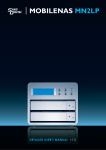
MOBILENAS MN2LP
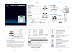
Front Cover
Page 5
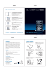
Package Contents
Installing a Hard Drive (Continued)
MN2LP .............................................................................................. 1
Fig.1
Fig.3
Fig.2
Power Cord ..................................................................................... 1
Manual ............................................................................................ 1
MOBILENAS MN2LP
HD Tray Keys ................................................................................... 2
Removable Tray Modules (Screws Included) ............................. 2
QUICK INSTALLATION GUIDE v1.0
(Please contact Sans Digital in case of missing or damaged items)
Hardware Diagrams
FRONT
Hardware Connections
Printer
LCD
LCD Screen
DHCP / STATIC IP ADDRESS
Ethernet Cable ............................................................................... 1
Network Switch Rear Panel
MS1UT
Select Buttons
ESC Button
Alarm LED
Mute Button
Enter Button
IP:DHCP
NoRaid
192.168.100.172
CURRENT RAID MODE
CURRENT IP ADDRESS
The IP is setup via DHCP by default. If the unit is able to obtain an IP address via the DHCP server, the IP
address will be displayed on the LCD. Please proceed to ‘Hard Drive Setup’ with the obtained IP
address. If the unit is unable to obtain an IP address, the LCD will display 192.168.001.001. The IP address
could be assigned or change via the unit’s LCD or IP managment Utility.
1. Press the Enter button
2. Press Up arrow and navigate to System Setup. Press Enter and enter password: 00000000.
3. Press Up arrow and navigate to IP Setup. Press Enter.
3. Select No for DHCP.
4. Follow the onscreen instructions, and change the IP address using Up and Down arrows and
Enter button to confirm.
Tray Handle
Lock
BACK
HDD LED State
IP Management Utility Setup
Power Socket
IP Management Utility:
Username: admin
Password: admin
Power Switch
USB2.0
Giga Lan
Giga LAN
Giga Lan
K
USB
K
USB
Step 2
The setup software will automatically find the NAS unit
and information is shown as the following screen. If
there are multiple MobileNAS MN2L devices on the
network, all detected MN2L will be shown on the left.
The NAS unit’s IP address and other networking
property will be display on the screen. First select the
server name and press OK.
Step 1
Power on the unit until the status LED remains blue.
Run “IP Setup.exe” located in the User Manual CD
and click “Setup” when the window appears.
RESET
Please ensure each plug is
properly connected before
turning on the power.
Please ensure each plug is
properly connected before
turning on the power.
Installing a Hard Drive in the Removable Tray Module
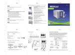
1. Press the key (included with this unit) into the lock hole located at the front of the unit. Pull
handle and remove tray.
2. Demount the plastic tray protector by removing the screws in the illustration below Fig.1.
3. Fasten the Hard Drive with the screws (included with this unit) in the corresponding locations
in illustration Fig.2. Place the tray with the mounted HDD back into the case.
QUICK INSTALLATION GUIDE v1.0
IP Management Utility Setup (Continued)
ntinued)
Note:
The default setting is DHCP, which it will obtain the IP
address automatically. Changing the network setting
to MANUAL / STATIC IP is highly recommended.
Step 4
You can choose whether to use static IP address, or
to automatically obtain an IP address from a DHCP
server. Press Next to confirm the setting.
Step 3
Enter The administrator username and password. The
default username is ‘admin’, and the default
Other Sans Digital Products
Hard Drive Setup
Step 1
Before the unit is ready to use, the installed hard drive
will require initialize or format. Open a Web Brower
(Internet Explorer) and type in the NAS IP address.
When prompt for the username and password, type
in the administrator username and password.
Step 2
If the inserted Hard Drives are not formatted, go to
“Basic” -> “Maintenance” -> “Disk Utility” for single
hard drive setup or Select “RAID Setting” for RAID
configuration Setup.
MS1UT/MS1CT
• 3.5” Hard Drive Enclosure with Removable Tray
• Dual Host Interface: USB 2.0, eSATA (MS1UT).
• Quad Host Interface: USB 2.0, eSATA, Firewire 800 and 400 (MS1CT).
• Supports High Performance SATA Hard Drives.
• Ultra Quiet Operation.
• Vertical Placement Stand Included.
• Both Mac OS X and Windows Supported.
MS2UT/MS2UB
• 2-Bay External RAID Enclosure
• RAID Design, supports RAID 0, 1.
• eSATA and USB 2.0 (MS2UT) or Firewire 800 & USB 2.0 (MS2UB).
• Drive Interface: 3.5” x 2 SATA I/ SATA II Hard Drives.
• Hot-Swappable Removable Tray.
• Data Auto-Rebuilding.
• Hard Disk, Fan and Temperature failure detectors.
MS4T/MS4UM
• 4-Bay External RAID Enclosure
• Support JBOD for independent access up to four hard drives.
• 1394b x 2 (MS4B), eSATA x 4 (MS4T), USB 2.0 & Port Multiplier (MS4UM).
• Drive Interface: 4 x 3.5" SATA I / SATA II Hard Drives.
• RAID supported in MS4UM (software RAID 0, 1, 0+1, 5, 5 + spare in
Windows and MAC).
• OS independent with plug and play capability.
password is ‘admin’.
Step 5
Date and Time information will be set in the following
Windows. Change the desire time zone, date and
time, and press Next to confirm.
Step 6
The system confirmation screen will be display. Click
on “Save” and the NAS unit will restart and the new
setting will be active.
Step 2 (Continued)
If the inserted Hard Drives has been format, “Disk
Utility” and “RAID Setting” will be located in “Control
Panel” -> “Maintenance”.
Step 3
You can now follow Basic -> Add User to create user
and Basic->Add Share to create a share folder.
MR5S1/MR5CT1
• 5-Bay External RAID 6 Enclosure
• Hardware RAID Design, supports RAID 0, 1, 0+1, 3, 5, 6, JBOD & Hot
Spare Disk.
• SCSI Ultra 320 (MR5S1)/ USB 2.0, Firewire 800 & eSATA (MR5CT1).
• Drive Interface: 5 x 3.5” SATA I / SATA II Hard drives.
• Hot-Swappable Tray Design.
• Hard disk, fan and temperature failure detectors.
W: WWW.SANSDIGITAL.COM E: [email protected] T: 1.800.980.1988 F: 1.626.322.3878
Page 1
Page 2
Page 3