Transcript
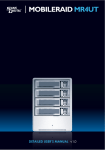
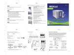
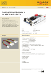
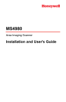
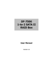
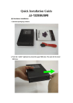
Front Cover
MOBILERAID
Page 1
MR5S1 | MR5CT1
Page 2
Package Contents
Hardware Diagrams
(Please contact Sans Digital in case of missing or damaged items.)
Tray Panel
Front Panel
Included
MR5S1/ MR5CT1 unit............................................................ 1
RS232 cable.......................................................................... 1
Removable Tray................................................................... 5
Power cord........................................................................... 1
Tray Key................................................................................. 2
Screws................................................................................... 32
User’s Manual........................................................................ 1
HDD LED Status
r
to
ca
di
In
D
LE
)
D
IT
D
X
H
(E
C T)
S
E EN
(
R
n
tio
ec
el on
S utt
B
TE
N
P
ow
Te er
m
p
Fa era
tu
n
re
D
et
ec
to
r
E
MR5S1 Only
Lock Hole
Tray Handle
MR5S1/MR5CT1
INSTALLATION MANUAL
SCSI cable............................................................................. 1
Terminator............................................................................. 1
MR5S1 Host Connection
Terminator
Computer Rear Panel
USB2.0
MR5CT1 Only
1394a
1394b cable.......................................................................... 1
USB cable.............................................................................. 1
eSATA cable......................................................................... 1
Installing HDD in the Removable Tray
1. Demount the plastic tray protector.
RS232
2. Mount the HDD into the tray.
SCSI
LAN
Terminator
Switch HUB
Intranet
QUICK INSTALLATION GUIDE v1.0
If the screws are not properly fastened the hard disk may be pushed towards the back of the unit & the tray handle will not open properly.
MR5CT1 Host Connection
Computer Rear Panel
Total X Disks
RAID 0
RAID 1
RAID 0+1
RAID 1+Spare
RAID 0+1+Spare
RAID 3
RAID 3+Spare
RAID 5
RAID 5+Spare
RAID 6
RAID 6+Spare
Power On
USB
USB2.0
1394a
MR5CT1
Ready
(Enter)
eSATA
USB
1394b
Password
Note.1
To Ethernet for Remote Management
Please make sure Channel Setting is set to Channel 1 or Channel 0+1 once Volume Set has been created. USB 2.0,
1394b and eSATA connections utilize Channel 1 setting.
Quick Volume / RAID Setup
Quick Volume and RAID Setup are the fastest ways to prepare a RAID set and volume set. You
only need a few simple keystrokes to complete. Although disk drives of different capacities may
be used in the RAID set, the MR5S1/ MR5CT1 will use the smallest capacity of the disk drive as
the capacity of all disk drives in the RAID set.
The Quick Volume and RAID Setup option creates a RAID set with the following properties :
1. All of the physical disk drives are contained in a RAID set.
2. The RAID levels associated with hot spare, capacity, and stripe size are selected during
the configuration process.
3. A single volume set is created and consumes all or a portion of the disk capacity
available in this RAID set.
(Please See the Diagram on Next Page)
Page 3
Stripe Size
64k Bytes
Note.3
(ENT)SEL : To Create
(ESC)EXIT : To Abort
Quick Volume and
RAID Set Setup
LAN
GUI
Other Sans Digital Products
Total : xxx GB
Select : xxx GB
Note.2
RS232
• Please connect the SCSI terminator before setting up the MR5S1 or the device will not be detected.
• For Quick Installation the SCSI ID default is 0, however, if you need to change this please refer to the User's Manual on the CD.
MS1UT
(ENT)SEL : FGrnd Init
(ESC)EXIT : BGrnd Init
Volume Set # 00
Initialize100.0%
The MR5S1/MR5CT1 does not set a default RAID level, please set your desired RAID level after the device
boots up. When setting the RAID level, please make sure that all hard disks inside the unit display a
Note 1: Password:0000
MS2UT+/MS2UTN+
• 2-Bay External RAID Enclosure
• Hardware RAID design, supporting RAID 0, 1, JBOD, BID, SAFE33, and
SAFE55, with eSATA and USB 2.0 interfaces.
• Drive Interface: 3.5” x 2 SATA I/ SATA II hard drives.
• Hot-swappable removable tray.
• Data auto-rebuilding.
• Hard drive, fan and temperature failure detectors.
MS4B/MS4T/MS4UM
• 4-Bay External RAID Enclosure
• Support JBOD for independent access up to four hard drives.
• 1394b x 2 (MS4B), eSATA x 4 (MS4T), USB 2.0 & Port Multiplier (MS4UM).
• Drive interface: 4 x 3.5" SATA I/ SATA II hard drives.
• RAID supported in MS4B (RAID 0) and MS4UM (software RAID 0, 1,
0+1, 5, 5 + spare in Windows).
• OS independent with plug and play capability.
Note 2: The number of physical drives in a specific RAID set determines the RAID levels
that can be implemented with the RAID set.
Minimum #
of Physical
Drives
Required Per
RAID Set
RAID 0
RAID 1 RAID 1 RAID 3 RAID 3
+Spare
+Spare
RAID 5
RAID 5
+Spare
RAID 6
RAID 6
+Spare
1
or
more
2
or
more
3
or
more
4
or
more
4
or
more
5
or
more
3
or
more
3
or
more
4
or
more
Note 3: Stripe size default is 64k, it can adjust to 4k or 128k mode under stripe size.
Note 4: Please refer to the enclosed CD for the detail user's manual.
Note 6: For Remote Management the IP address will be displayed in the LCD Display located
on the front of the unit. The default use name & default password is:
Note 6: For Remote Management the IP address will be displayed in the LCD Display located
on the front of the unit. The default use name & default password is:
User Name: admin
Password: 0000
Page 4
• 3.5” Hard Drive Enclosure with Removable Tray
• Dual host interface: USB 2.0 and eSATA.
• Supports High Performance SATA hard drives.
• Ultra quiet operation.
• Vertical placement stand included.
• Durable aluminum housing.
• Supports both Windows and Mac OS X.
MR5S1/MR5CT1
• 5-Bay External RAID 6 Enclosure
• Hardware RAID design, supports RAID 0, 1, 0+1, 3, 5, 6, JBOD & hot
spare disk.
• SCSI Ultra 320 (MR5S1)/ USB 2.0, Firewire 800 and eSATA (MR5CT1).
• Drive interface: 5 x 3.5” SATA I / SATA II hard drives.
• Hot-swappable tray design.
• Hard disk, fan and temperature failure detectors.
T: 1.800.980.1988 F: 1.562.949.3328 E: [email protected] W: WWW.SANSDIGITAL.COM
Page 5