1
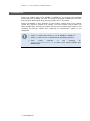
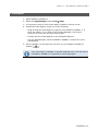
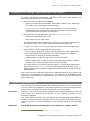
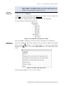
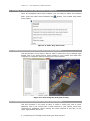
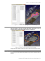
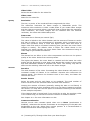
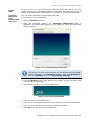
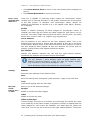
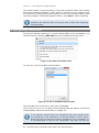
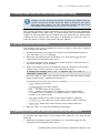
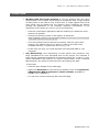
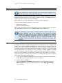
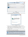
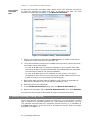
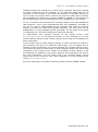
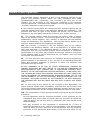
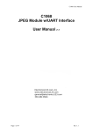
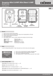
Video 1.1 - User Manual | February 2015 APPS VIDEO 1.1 - USER MANUAL FEBRUARY 2015 Video 1.1 - User Manual | February 2015 ©FARO Technologies Inc., 2015. All rights reserved. For personal use, this publication may be reproduced or transmitted. For commercial use, no part of this publication may be reproduced, or transmitted in any form or by any means without written permission of FARO Technologies Inc. FARO TECHNOLOGIES, INC. MAKES NO WARRANTY, EITHER EXPRESS OR IMPLIED, INCLUDING BUT NOT LIMITED TO ANY IMPLIED WARRANTIES OF MERCHANTABILITY OR FITNESS FOR A PARTICULAR PURPOSE, REGARDING THE FAROARM, FARO LASER TRACKER, FARO LASER SCANNER AND ANY MATERIALS, AND MAKES SUCH MATERIALS AVAILABLE SOLELY ON AN “AS-IS” BASIS. IN NO EVENT SHALL FARO TECHNOLOGIES INC. BE LIABLE TO ANYONE FOR SPECIAL, COLLATERAL, INCIDENTAL, OR CONSEQUENTIAL DAMAGES IN CONNECTION WITH OR ARISING OUT OF THE PURCHASE OR USE OF THE FAROARM, FARO LASER TRACKER, FARO LASER SCANNER OR ITS MATERIALS. THE SOLE AND EXCLUSIVE LIABILITY TO FARO TECHNOLOGIES, INC., REGARDLESS OF THE FORM OF ACTION, SHALL NOT EXCEED THE PURCHASE PRICE OF THE MATERIALS DESCRIBED HEREIN. THE INFORMATION CONTAINED IN THIS MANUAL IS SUBJECT TO CHANGE WITHOUT NOTICE AND DOES NOT REPRESENT A COMMITMENT ON THE PART OF FARO TECHNOLOGIES INC. ACCEPTANCE OF THIS DOCUMENT BY THE CUSTOMER CONSTITUTES ACKNOWLEDGMENT THAT IF ANY INCONSISTENCY EXISTS BETWEEN THE ENGLISH AND NON-ENGLISH VERSIONS, THE ENGLISH VERSION TAKES PRECEDENCE. FARO Technologies Inc. Internal Control File Location: X:\CONTROL\RECORDS\05MANUFA\PARTSPEC\7 Software\E1069_Video_1.1_Manual_EN.pdf Video 1.1 - User Manual | February 2015 Table of Contents Table of Contents ................................................................................... 1 1. Introduction ........................................................................................ 3 2. Installation .......................................................................................... 4 3. Licensing ............................................................................................ 5 4. Creating a Fly-Through Video from your Scan Project .................................. 6 4.1. Create Viewpoints Manually ............................................................ 6 4.2. Defining a Camera Path with automatic Viewpoints ............................ 9 4.2.1. Create path from scanner positions with view along the path ............. 9 4.2.2. Create path from scanner positions with view around the path ........... 9 4.2.3. Create path over scanner positions from a bird’s-eye view ................10 4.3. Video from path ...........................................................................10 4.4. Video from images .......................................................................11 4.5. Camera Path Settings....................................................................11 4.5.1. Create Camera Path .................................................................12 4.5.2. Camera Path Shape ..................................................................13 4.5.3. Preview ...................................................................................15 4.6. Configure the Video / Rendering Settings ..........................................17 4.6.1. Settings in 3D View - Visibility Settings .............................................17 4.6.2. Video Settings ...........................................................................17 4.7. Rendering the Video Frames and Creating the Video ..........................22 4.8. Editing Existing Camera Paths .........................................................23 4.9. Creating Video Frames and Videos from Exisitng Camera Paths ............24 4.10. Creating Videos from Already Rendered Video Frames ......................25 4.11. Distributed Rendering ..................................................................26 5. Creating Videos with the Third-Party Application FFmpeg ...........................28 5.1. Encoding Videos from Frame Images ...............................................28 5.2. Combining Two Videos (left and right) into one Side-by-side Video File ............................................................................................28 5.3. Combining Two Videos (left and right) into one Anaglyph Video File ......29 6. Known Issue .......................................................................................30 7. Licensing Video Pro .............................................................................31 7.1. Single-User License ........................................................................31 7.2. Network Licensing (Floating License) ................................................33 Technical Support ..................................................................................35 Software License Agreement ...................................................................37 Implementation Notes ............................................................................39 paintlib ............................................................................................39 Video 1.1 - User Manual | February 2015 Trademarks .......................................................................................39 Video 1.1 - User Manual | February 2015 1. Introduction Video is a helpful add-on for SCENE or SCENE LT. It extends the standard functionality by enabling the user to create fly-through animations from their scan projects and export them as high quality 2D or 3D videos. Video is available in two versions: a free version (Video) and a pro version (Video Pro) which is subject to a charge. The free version covers nearly the same functionality as the pro version but has an animated water mark in the resulting fly-through videos and rendering of stereoscopic videos is not supported. Video 1.1 works with version 5.1.2 of SCENE or SCENE LT. Video 1.1 will not run on Windows XP operating systems. View online tutorials in the Internet at http://tutorial.faroeurope.com to learn more about SCENE and SCENE apps. 3 | Introduction Video 1.1 - User Manual | February 2015 2. Installation 1. Open SCENE or SCENE LT. 2. Open the App Manager under Tools Apps. 3. If a previous version of the Video App is installed, remove it first. 4. Install the Video App by doing one of the following: o Drag & drop the Video App file (.fpp file) into SCENE or SCENE LT. It does not matter, if you drop it into the App Manager, the Project Overview or even into an open scan project. o Double click the Video App file in the Windows Explorer. o Use the App Manager (see the SCENE or SCENE LT manual for more information). 5. Once installed, you should have this icon in your SCENE or SCENE LT toolbar: . This Video App is available in English language only, but also works if SCENE or SCENE LT is operated in other languages. Installation | 4 Video 1.1 - User Manual | February 2015 3. Licensing If you use the free version of Video, activating is not required. Video Pro Once installed, you may fully test Video Pro for 7 days without the need of a software license. After the trial period, Video Pro will be disabled and you need a license to further use the Video App. See chapter 7 for more information on how to license Video Pro. 5 | Licensing Video 1.1 - User Manual | February 2015 4. Creating a Fly-Through Video from your Scan Project To create fly-through animations and videos from your scan project, the following tasks have to be accomplished: Select one of four Video path creations: o Select one of the three automatic Video path creations. The Video App will create a set of suitable Viewpoints then. o Create Viewpoints on your own in the 3D View of your scan project. Viewpoints will be used as key frames for the path along which the virtual camera moves within the 3D scene. Set up the fly-through animation by defining the Camera Path: o select the Viewpoints to be used. o bring them into the right order. The Camera Path will be created by connecting the selected Viewpoints in the defined order. The virtual camera will move along this path. Configure the Video / Rendering Settings and create the fly-through video. Video creation can be separated into three steps: o Video renders single still images (frame images) for each video frame and saves them to the hard disk. The frame images are created by interpolation to achieve a smooth animation. o Video renders a video file and saves it to the hard disk. o Video renders both, a video file and single still images (frame images) for each video frame and saves them to the hard disk. The video file can be created with Video App, or a third-party application with which you can distribute the very time consuming rendering of the frame images across multiple computers to reduce overall render times by parallelization. The result will be a video file which can be played backed on any system and which can, for example, be published on the Internet or embedded within PowerPoint presentations to demonstrate your scan project to customers or other audiences. 4.1. Create Viewpoints Manually You can save the current position and viewing direction of the virtual camera in the 3D View as a Viewpoint. This allows returning to saved Viewpoints later at any time and using them as key frames for the Camera Path. Key frames Typically, key frames mark those positions and viewing directions in the 3D View where the directional movement or the viewing direction of the animation changes. The single frames between two key frames are automatically interpolated to achieve a smooth camera movement from one key frame to the following. So, there is no need to create Viewpoints for each single frame of the animated video. Viewpoints You need at least two Viewpoints or key frames to create a video1. 1 See http://en.wikipedia.org/wiki/Key_frame for more information. Creating a Fly-Through Video from your Scan Project | 6 Video 1.1 - User Manual | February 2015 When you have moved the position of the virtual camera in the 3D View to a position that you would like to use as a key frame for the Camera Path, you can create a Viewpoint from it. Viewpoints are added to the folder Viewpoints in the Structure Window. They are part of the Workspace and will be saved with the project’s Workspace. Figure 4-1: Viewpoints in the Structure Window Follow these steps to create the Viewpoints for your Camera Path: 1. Create a project point cloud of your scan project. This ensures optimal rendering performance and highest visual quality. (At least, there should be scan point clouds for all scans of the workspace.) o Remove duplicate points and stray points when creating the project point cloud to achieve the best possible result. 2. In the 3D View of the scan project, navigate to the position you would like to use as the starting point for your Camera Path. You can zoom in or zoom out as well. 3. Create a Viewpoint for this position and viewing direction with Ctrl + F2 , or click the button in the 3D View toolbar. o If it is impossible to catch a Viewpoint in the 3D View of the scan project, you can also open the corresponding scan and create the Viewpoint there. o You can change the default name to something that explains the Viewpoint. This may be helpful later on when you have to organize the camera path. 4. Navigate again to move the virtual camera to the position that you would like to use as the next key frame, then create the next Viewpoint. 5. Continue and repeat these steps until all Viewpoints or key frames have been created. You can still change their order or exclude unwanted Viewpoints in the next step when defining the Camera Path Settings. Better do not mix up Viewpoints with perspective and orthographic cameras in the one and the same Camera Path. In most cases, Viewpoints with a perspective camera are sufficient. Viewpoints should be in about the same distance from another. 7 | Creating a Fly-Through Video from your Scan Project Video 1.1 - User Manual | February 2015 Avoid defining Viewpoints which are placed closed-up and in sharp angles. The Camera Path will run in sharp edges which makes it uncomfortable to watch the video. Organize Viewpoints To go to an already created Viewpoint, right-click its name in the Structure window, then click Activate. Viewpoints can be successively activated in the order of their creation by using F2 or in reverse order by using Shift+F2. The name of a viewpoint should not have more than 20 characters. You can organize Viewpoints into folders: Figure 4-2: Viewpoints grouped into folders See the SCENE or SCENE LT manual for more information on Viewpoints. Defining a Camera Path Once all Viewpoints have been created, you can start to define the Camera Path. Click the beneath the menu. button in the Video toolbar, or click the small arrow button, then select New Path from the toolbar drop down Figure 4-3: Video drop down menu Continue with chapter 4.5 Camera Path Settings. Creating a Fly-Through Video from your Scan Project | 8 Video 1.1 - User Manual | February 2015 4.2. Defining a Camera Path with automatic Viewpoints Once all Viewpoints have been created, you can start to define the Camera Path. Click the small arrow beneath the menu opens. button. The toolbar drop down Figure 4-4: Video drop down menu 4.2.1. Create path from scanner positions with view along the path Use this function if you want to have a video in which the view is always right ahead, like if you would hold a video camera in your hands and walk from viewpoint to viewpoint without moving the video camera. Figure 4-5: View along the path (pink arrows) 4.2.2. Create path from scanner positions with view around the path Use this function if you want to have a video in which the view is more spacious, like if you would hold a video camera in your hands, walk from viewpoint to viewpoint, while moving the video camera to the left, to the right, right ahead, and so on. 9 | Creating a Fly-Through Video from your Scan Project Video 1.1 - User Manual | February 2015 Figure 4-6: View around the path (pink arrows and shades) 4.2.3. Create path over scanner positions from a bird’s-eye view Use this function if you want to watch the scenery from above. A set of viewpoints will be created which enable a view on a circled line. Figure 4-7: Bird’s-eye view and Camera Path settings Imagine that the camera is fixed at the red line and is driven along the circle. 4.3. Video from path Select this if you have created video paths and you want to continue with one of them. Creating a Fly-Through Video from your Scan Project | 10 Video 1.1 - User Manual | February 2015 After clicking Video from path, the Load camera path dialog opens. Select a camera path and click Load. The Camera Path Settings dialog is displayed, and you can continue with your settings. If no camera path is available and you close the dialog, the Camera Path Settings dialog is displayed as well, but in the Create new path view. 4.4. Video from images Select this if you have rendered images and you want to have a video out of these pictures. After clicking Video from images, a dialog opens in which you can browse for a set of images which is saved in a .vapp file. This file should be available in the same directory in which the images were saved. Click Open to use the set of images. The Video Settings dialog is displayed, and you can continue with your settings. 4.5. Camera Path Settings This dialog will show up: Figure 4-8: Camera Path dialog 11 | Creating a Fly-Through Video from your Scan Project Video 1.1 - User Manual | February 2015 4.5.1. Create Camera Path The SCENE Viewpoints list on the left contains all Viewpoints listed in the Structure window in folder Viewpoints. Click the Viewpoints you would like to use for the Camera Path from this list, then click the Add button. Or, drag and drop them. You can click several Viewpoints by using the Shift or CTRL key while clicking. The added Viewpoints will be copied into the Camera Path Viewpoints list on the right. It contains all the Viewpoints used for generating the Camera Path. The Viewpoints are used in the displayed order. Double-click a Viewpoint to view it in the 3D View of your scan project. Figure 4-9: Viewpoints in the Camera Path Change order To change the order of the Viewpoints in the Camera Path, select the Viewpoint in the Camera Path Viewpoints list, move it with the Move up or Move down button until it is in the correct position. Or, drag and drop it to its new position. You can click several Viewpoints by using the Shift or CTRL key while clicking. Creating a Fly-Through Video from your Scan Project | 12 Video 1.1 - User Manual | February 2015 A Viewpoint can be used multiple times in one and the same Camera Path. You can create and add further Viewpoints to the workspace while the Camera Path dialog is open. They will automatically appear in the SCENE Viewpoints list. Camera Paths created with the free version of Video are compatible with Video Pro and vice versa. Remove Viewpoints To remove a Viewpoint from the Camera Path, select the Viewpoint in the Camera Path Viewpoints list, click the Remove button. Hot keys Q Delete selected Viewpoint(s) W Add selected Viewpoint(s) A Select all Viewpoints in the list S Invert selection E / D Move selected Viewpoint up / down Geo referencing of scan points may introduce very large translations for each individual scan of the project. For example, a scan may be translated thousands of kilometers along the x and/or y axis. These translations may lead to an uneven Camera Path. Such a Camera Path behavior can easily be observed when previewing the path. In this case Close all open dialogs of the Video App, Right-click Workspace in the Structure Window, then click Operations Registration Move Clusters to Center of Scans (available in SCENE, not in SCENE LT). You can then continue working with the Video App. 4.5.2. Camera Path Shape Interpolation includes video path viewpoints The Video path is led through the viewpoints. In some cases, the video pans may occur somewhat unsteady or even bumpy, especially if the camera moves with higher speed. If you feel uncomfortable while watching the video, it may be worth trying the second setting. 13 | Creating a Fly-Through Video from your Scan Project Video 1.1 - User Manual | February 2015 Figure 4-10: Interpolation includes video path viewpoints Interpolation excludes video path viewpoints The Video path is led along the viewpoints. In most cases, the video pans look smoother what makes it more comfortable to watch. The viewing direction will not change. Figure 4-11: Interpolation excludes video path viewpoints Loop path Save Path Select to loop the Camera Path. This will close the gap between the last and the first Viewpoint. This is, for example, useful if you want to show your video in an endless loop at exhibition stands. Saves the current Camera Path to the project’s workspace. The path will be added to the folder CameraPaths. Creating a Fly-Through Video from your Scan Project | 14 Video 1.1 - User Manual | February 2015 Save Path As Saves the Camera Path as a new path to the project’s workspace. Figure 4-12: Folder CameraPaths in the Structure Window 4.5.3. Preview Show Camera Path Visualizes the Camera Path and the key frames in the 3D View. Three colored curves represent the Camera Path: Red curve: the Camera Path, consisting of the interpolated camera positions. The curve’s length in meters is shown in the title of the Camera Path dialog. Yellow curve: represents the center of the field of view in 1 meter distance from the camera position. The black line between the key frame and the yellow curve illustrates the viewing direction. Orange curve: represents the area above the camera. The black line between the key frame and the orange curve illustrates the corresponding up vector. The key frames or Viewpoints will be visualized as black cubes, if you see them in the 3D view of a scan, and they are visualized as a laser scanner symbol when you see them in the 3D view of the scan project. Displaying the path in the 3D View can help to identify collisions with objects or overshooting of the interpolated path. Figure 4-13: Camera Path in a scan’s 3D View 15 | Creating a Fly-Through Video from your Scan Project Video 1.1 - User Manual | February 2015 Figure 4-14: Camera Path in the scan project’s 3D View Preview Path Preview the fly-through animation of the defined Camera Path in the 3D View of your scan project. The following dialog will appear when viewing the animation. It allows controlling the preview. Figure 4-15: Preview dialog Play / Pause Stop / – Play / Pause the preview. - Stop the preview and go back to the first frame. Previous key frame Previous frame Next frame Next key frame Loop - Go to previous Viewpoint / key frame. - Go to previous frame. - Go to next frame. - Go to next Viewpoint / key frame. - Loop the preview. Close the preview and return to the previous dialog with the button. Hot keys Space Play / Pause Return Stop / Go to first Viewpoint / key frame Arrow down Go to previous Viewpoint / key frame Arrow up Go to next Viewpoint / key frame Arrow left Go to previous frame Arrow right Go to next frame Creating a Fly-Through Video from your Scan Project | 16 Video 1.1 - User Manual | February 2015 When previewing, depending on system performance, not all scan points are loaded and displayed. The resulting video will of course have all visible points in each frame and will thus have a better visual appearance than the preview in the 3D View. To change the speed of movement / length of the preview, change the video length in the rendering settings which can be accessed with the Next button of the Camera Path dialog. For more information, see chapter 4.6. The Camera Path (red curve) consists of line segments between the single interpolated camera positions. If the path has an obvious angular shape, this might be a sign for an insufficient number of interpolated camera positions in the path. Try to increase the number of frames and thus the number of camera positions by increasing the frames per seconds (fps) or by increasing the video length in the rendering settings dialog. Once the path is complete, click the Next>> button to continue with Configuring the video / rendering settings. 4.6. Configure the Video / Rendering Settings 4.6.1. Settings in 3D View - Visibility Settings Some of the 3D View visibility settings (open with the button in the Standard toolbar) have an effect on the resulting frame images and video: Layer tab Objects visible in the 3D View will also be visible in the frame images and the video. Turn their visibility on or off. Extra tab Scan positions will also be visible in the frame images and the video. Turn their visibility on or off. View tab Choose a neutral background color and to turn color gradient off. Enabling the stereoscopic mode in the 3D View visibility settings does not have an effect on the frame images and the video. Scan Points tab Turn gap filling off to avoid video flickering. Enabling Clear View does not have an effect on the frame images and the video. Point size does not scale with the chosen resolution. Increasing the resolution at constant point size increases the distance between the points and might thus lead to transparency of objects like walls. In that case, increase the point size to improve the look of the resulting video. For more information on the 3D Visibility settings, read the SCENE or SCENE LT User Manual. 4.6.2. Video Settings When creating the fly-through video, Video first renders one image file for each video frame (two for stereo videos). These frame images are used to create the video. You can use Video or other third party applications to produce a video file from the images. 17 | Creating a Fly-Through Video from your Scan Project Video 1.1 - User Manual | February 2015 The video settings dialog allows configuring the properties of the frame images and the resulting video: Figure 4-16: Video settings File Settings Image folder Select the save folder for the frame images. Image base name Base name for the frame image files. They will have a numeric suffix according to the frame number. For example, if “img” is the base name, the file names will be img0001.png, img0002.png etc. Video format The video file type and codec used to produce the video. You can select between .wmv (wmv3)2 and .mp4 (H.264)3. 2 http://en.wikipedia.org/wiki/WMV3 http://en.wikipedia.org/wiki/H.264. Note that the H.264 video codec is not free for commercial use. You might have to buy a license if you commercially use the videos encoded with H.264. Additional information may be obtained from MPEG LA, L.L.C. See http://www.mpegla.com. 3 Creating a Fly-Through Video from your Scan Project | 18 Video 1.1 - User Manual | February 2015 Video folder Select the save folder for the video file. Video name Name for the video file. Quality Resolution The size, in pixels, of the rendered frame images and the video. The maximum resolution for frame images is 7680x4320 pixels. The maximum video resolution is 1920 x 1080 pixels. If you create frame images and the video at once and select a resolution that is higher than the maximum video resolution, the frame images will be rendered with the selected resolution, the video with 1920x1080 pixels. Frame rate The frame rate in frames per second (fps). This value is linked to the video duration and the amount of frames to render and has an effect on the smoothness of animation which increases as the frame rate increases. Keep in mind that higher frame rates also result in larger video files and an increased rendering time (as there are more frame images to render). The default value is 30fps. For videos shown in the Internet you would typically use lower frame rates. We recommend using at least 24fps to get smooth animations. Bitrate The bitrate has an effect on the video compression and thus on the picture quality of the video. Select from various presets. The higher the bitrate, the more detail is retained and the better the video quality will be. But keep in mind that a high bitrate also results in large video files and bandwidth needed to playback the video. This setting only has an effect on the resulting video and not on the frame images. General Duration The total duration of the video. Increasing the video duration will result in an increased number of frames to be rendered. Duration also influences the camera speed. The shorter the duration time of the video, the faster the camera will move. Render frames Select the start and the end frame to be rendered. The total number of frames results from the selected frame rate and video duration. Limiting the number of frames (manually setting the start or end frame) is useful for rendering a short snapshot video or a few frame images to preview the results. You may also use this option to distribute rendering of the frames across multiple computers. If the Camera Path is looped and if you would like to play the resulting video in an endless loop you should not limit the number of rendered frames. See chapter 4.11 for more information on this. Camera acceleration Camera moves with constant speed when set to None (acceleration is disabled), otherwise the camera accelerates at the beginning of the path and decelerates at the end. Select from various presets. It is recommended to disable acceleration when looping the video. 19 | Creating a Fly-Through Video from your Scan Project Video 1.1 - User Manual | February 2015 Preview Video Customize Watermark (only available with Video Pro) Click to Preview Video the fly-through animation in the 3D View of your scan project according to the settings made in this dialog. Previewing the video is similar to previewing the Camera Path. See chapter 4.2 for more information. You can add a watermark to personalize the video. If you want to have a watermark, check the Enable checkbox. Click the Customize button. The Customize Watermark dialog is displayed. The empty field stands for your display in which the watermark shall be inserted: Figure 4-17: Customize Watermark dialog The background color of the preview can be defined with the SCENE Visibility settings: in the Structure window, right-click Workspace, then click Visibility, then click 3D Visibility Settings... Click the Browse button, then browse your folders for the file which shall be inserted as a watermark. The picture is inserted in the lower left corner. Figure 4-18: Picture with handles Click and move it to another place. Click one of the handles at the corners to resize the picture symmetrically. Click one of the handles at the sides to distort the picture. Click OK to use the picture as a watermark. Creating a Fly-Through Video from your Scan Project | 20 Video 1.1 - User Manual | February 2015 Click Reset Default View to return to the view directly after browsing the picture. Click Delete Watermark to remove the picture. Stereo (only available with Video Pro) Video Pro is capable of producing frame images for stereoscopic videos. Viewing your fly-through animation in 3D greatly enhances the 3D perception of the scan project. To playback such stereoscopic videos, specific 3D software and hardware is required (e.g. a 3D capable video player, beamer, TV or Monitor) Enable Enable or disable rendering of frame images for stereoscopic videos. If enabled, the Video App will render two offset images for each frame, one for each eye. The frame image files will have the suffix l (for left) and r (for right) before their numeric suffix, e.g. imgl001.png, imgr001.png. Focus distance Set the distance of the camera to the Zero Disparity Plane. This is the distance from the camera to objects that will appear as they are in the plane of the display. Objects closer to the camera than this value (objects in front of the Zero Disparity Plane) appear as they are between the viewer and the display; objects further away appear behind the display. Eye distance Change the distance between the left and the right camera position. Increasing the distance will increase the perceived depth. The eye distance / focus distance ratio for large screens (e.g. beamer) should be approx. 1:200; the ratio for smaller screens (e.g. monitors or TVs) should be approx. 1:30. Focus distances smaller than 500mm are recommended. Settings Default Reset all video settings to the default values. Save Save the settings as a settings file (with extension .vapp) to the hard disk. Load Load saved settings from the hard disk. Edit path Returns you to the Camera Settings. Create Images and / or Video Images Enable to render the frame images. Video Enable to render the video. Video and Images If both Images and Video are selected, the Video App will render the video once rendering of the frame images is complete. If stereo is enabled and two offset images for each frame are available, the Video App will create two video files, one for the left and one for the right camera position. These two 21 | Creating a Fly-Through Video from your Scan Project Video 1.1 - User Manual | February 2015 video files can then be used to playback your results in 3D4 or to produce a single 3D video file with an appropriate video tool5. Start The settings will automatically be saved to a settings file (.vapp) in the selected save folder and rendering will be started. Test renderings Once the settings have been made, it is recommended to render a few test frames and to have a look at the rendered image quality to prove the result, particularly when you want to render stereoscopic videos. You can then view the rendered frame image pairs in 3D, for example with the 3D video player “Bino”4, to verify the selected focus and eye distance. To get improved video quality, it is recommended to first render frame images with a higher resolution than the desired video resolution; then, in a second step, use the images to create the video in the desired resolution. You can use third-party applications for this or Video (see chapter 4.10 for more information). To improve rendering performance, the project should be stored on a local hard disk (for best performance use a SSD). 4.7. Rendering the Video Frames and Creating the Video Once rendering has started, this progress dialog will show up: Figure 4-19: Rendering dialog 4 To playback the results in 3D you may use the free 3D video player Bino (http://bino3d.org/) or the 3D Vision Video Player from NVIDIA (http://www.nvidia.com ). They can read both video files and output them in 3D. 5 E.g. with FFmpeg. See chapter 5. Creating a Fly-Through Video from your Scan Project | 22 Video 1.1 - User Manual | February 2015 This dialog shows a preview picture of the last rendered frame and informs about the rendering progress. It also gives an overview of the settings used for rendering. Clicking the preview picture of the last rendered frame opens the frame image in the default graphics editor. Click Stop to abort rendering. Before rendering the first frame, all visible scan points have to be loaded to the memory first. It may thus take a while until rendering the first frame. 4.8. Editing Existing Camera Paths If you have already saved one or more Camera Paths to the workspace, you can edit them by selecting Edit Path from the toolbar drop down menu. Figure 4-20: Video drop down menu You will get a list of available Camera Paths. Figure 4-21: List of available Camera Paths Click the path you would like to edit, then click Load. The Defining a Camera Path dialog of the selected path will appear. To edit the selected path, follow the instructions in chapter 4.2. If the selected Camera Path has Viewpoints that were deleted from the workspace in the meantime, you will be asked to recover them. Recovering will recreate the missing Viewpoints in the workspace. It is recommended to recover the Viewpoints; else they will not be 23 | Creating a Fly-Through Video from your Scan Project Video 1.1 - User Manual | February 2015 available when editing the path. 4.9. Creating Video Frames and Videos from Exisitng Camera Paths If you have already saved one or more Camera Paths to the workspace, you can create frame images and a video from them by selecting Video from Path from the toolbar drop down menu. Figure 4-22: Video drop down menu You will get a list of available Camera Paths. Figure 4-23: List of available Camera Paths Click the path, then click Load. If the selected Camera Path consists of Viewpoints that have been deleted from the workspace in the meantime, you will be asked to recover them. Recovering will recreate the missing Viewpoints in the workspace. It is recommended to recover the Viewpoints; else they will not be available in the Camera Path. The Video Settings dialog will appear. To set the video settings and to create frame images or a video from the selected path follow the instructions in chapter 4.6. Creating a Fly-Through Video from your Scan Project | 24 Video 1.1 - User Manual | February 2015 4.10. Creating Videos from Already Rendered Video Frames If you have already rendered frame images, you can create a video from them by selecting Video from Images from the toolbar drop down menu. Figure 4-24: Video drop down menu You will be prompted to select the video settings file that was saved when the images were rendered. Navigate to the folder with the rendered frame images and select the settings file (.vapp) in this folder. The Video Settings dialog will appear. 25 | Creating a Fly-Through Video from your Scan Project Video 1.1 - User Manual | February 2015 Figure 4-25: Rendering Settings You can now adjust the video format, resolution, frame rate, the video duration and the number of frames. Stereo will only be available if it was enabled for the rendering of the frame images. For more information, see chapter 4.6. 4.11. Distributed Rendering Distributed rendering is a technique to distribute the time consuming rendering of the image frames across multiple computers to reduce overall render times by parallelization. Each computer renders a certain number of frames. To do this, follow these steps: 1. Open the scan project on one computer, create the Viewpoints and define the Camera Path as described in chapters 4.1 and 4.2. 2. Save the path to the workspace. 3. Save your scan project or workspace to the hard disk. 4. Adjust the rendering settings and save them as a settings file to the hard disk as described in chapter 4.6. Creating a Fly-Through Video from your Scan Project | 26 Video 1.1 - User Manual | February 2015 5. Copy the scan project to each computer in order improve performance. 6. Open the scan project on each computer. 7. Select Video from path from the drop down menu of the Video toolbar and select the Camera Path that was defined in step 2. 8. The Configure the Video / Rendering Settings dialog will open. Load the settings file that was saved in step 4. 9. Adjust the save folder and the frames to be rendered on each machine (e.g. set start and end frames on the first computer to 1 to 1000, on the second computer to 1001 to 2000 etc.). Do not change the other settings. 10. Start rendering on each computer. 11. Once rendering is complete on all the computers, copy all frame images (and the settings file) into the same folder. 12. Render the video from the frame images with one computer using the Video App as described in chapter 4.10, or use another third party application. 27 | Creating a Fly-Through Video from your Scan Project Video 1.1 - User Manual | February 2015 5. Creating Videos with the Third-Party Application FFmpeg FFmpeg is a free-of-charge third-party solution that enables users to record, convert and stream audio and video. It brings its own audio and video codec library. You can download FFmpeg and find more information about this tool at http://www.ffmpeg.org/. This chapter provides a quick introduction to using the third-party application FFmpeg instead of the Video App, to create videos from the rendered frame images. It also describes how to combine the two video files for stereoscopic viewing into one side-by-side (left-right) or anaglyph 3D video file, that is a video file which is usually viewed with red/cyan glasses. 5.1. Encoding Videos from Frame Images This chapter gives you an example on how to encode a video from rendered frame images with FFmpeg: 1. Download FFmpeg and extract the content of the downloaded archive to your hard disk, e.g. to D:\FFmpeg. 2. Open the command prompt of Windows (e.g. by entering cmd into the input field of the Windows start menu). 3. In the command prompt, change the current directory to the directory of the frame images, e.g. D:\Frames. 4. Enter the following into the command prompt (the directory of the frame images is the current directory in the command prompt): D:\FFmpeg\bin\ffmpeg.exe -r 30 -i img%04d.png -b:v 10M -s 1920x1080 output.wmv This will create a .wmv video named output.wmv from the frame images named img0001.png, img0002.png and so on. D:\FFmpeg\bin\ffmpeg.exe: path to FFmpeg o -r 30: Frames per second. o -i img%04d.png: the input frames. img: the base name of the images, %04d: adjust to the number of numbers in the numeric suffix, i.e. %04d for four numbers (e.g. img0001.png) or %03d for three numbers (e.g. img001.png). o -b:v 10M: bitrate of the video in bit/s (M for million) (optional). o -s 1920x1080: The resolution of the output video in pixel (optional). o output.wmv: name (and video format) of the output video file. 5. Play the video, e.g. with the Windows media player. 5.2. Combining Two Videos (left and right) into one Side-by-side Video File To combine two video files in one side-by-side video file, you may do the following: 1. Open the command prompt of Windows (e.g. by entering cmd into the input field of the Windows start menu). Creating Videos with the Third-Party Application FFmpeg | 28 Video 1.1 - User Manual | February 2015 2. In the command prompt, change the current directory to the directory of the two video files, e.g. D:\Videos. 3. Enter the following into the command prompt (the directory of the videos is the current directory in the command prompt): D:\FFmpeg\bin\ffmpeg.exe -i videoright.wmv -vf "movie=videoleft.wmv [in1]; [in]pad=iw*2:ih:iw:0[in0]; [in0][in1] overlay=0:0 [out]" videoSbS.wmv This will create a side-by-side video named videoSbS.wmv from the two video files videoright.wmv and videoleft.wmv. videoright.wmv will be on the right side and videoleft.wmv on the left. The above mentioned command applies filters which are executed one after the other to create the side-by-side video. More information on FFmpeg filters can be found in the FFmpeg documentation under: https://ffmpeg.org/documentation.html and https://ffmpeg.org/ffmpeg-filters.html#Video-Filters The example above preserves the full vertical and horizontal resolution of the two videos and creates a side-by-side video with doubled width. Not all video players can handle such side-by-side videos. You can use the scale filters of FFmpeg to create a side-byside video with half horizontal resolution. Depending on the player, you may need to switch left and right video. 5.3. Combining Two Videos (left and right) into one Anaglyph Video File This will create an anaglyph video that can be viewed with red/cyan glasses. To combine two video files in one anaglyph video file you may do the following: 1. Open the command prompt of Windows (e.g. by entering cmd into the input field of the Windows start menu) 2. In the command prompt, change the current directory to the directory of the two video files, e.g. D:\Videos 3. Enter the following into the command prompt (the directory of the videos is the current directory in the command prompt): D:\FFmpeg\bin\ffmpeg.exe -i videoright.wmv -vf "movie=videoleft.wmv [inL]; [in]pad=iw*2:ih:iw:0[inR]; [inR][inL] overlay=0:0 [middle]; [middle] mp=stereo3d [out]" video3danaglyph.wmv 29 | Creating Videos with the Third-Party Application FFmpeg Video 1.1 - User Manual | February 2015 6. Known Issue Working with Very Large Projects: If you are working with very large projects and a lot of scans, there might be Viewpoints with a huge amount of scan points in the field of view. In this case, it might happen that not all scan points can be loaded into the memory when rendering the frames causing the application to not complete rendering successfully. If you experience such issues you can try one of the following: o Close all unnecessary applications before rendering to release as much memory as possible. o Change the following value in the registry of Windows: HKEY_CURRENT_USER\Software\FARO\SCENE5\Settings\PointLoadingF ield\MemoryFactorPointCaching o This value determines the amount of memory used for point cloud caching. The default value is 0.5 which is equal to the half of the available memory; increase this value to e.g. 0.8. o If this does not help, you could also add more physical RAM to your computer. Geo Referencing: Geo referencing of scan points may introduce very large translations for each individual scan of the project. For example, a scan may be translated thousands of kilometers along the x and/or y axis. These translations may lead to an uneven Camera Path. Such a Camera Path behavior can easily be observed when previewing the path. In this case o Close all open dialogs of the Video App, o Right-click Workspace in the Structure Window, then click Operations Registration Move Clusters to Center of Scans (available in SCENE, not in SCENE LT) o You can then continue working with the Video App. Known Issue | 30 Video 1.1 - User Manual | February 2015 7. Licensing Video Pro If you use the free version of Video, you may skip this chapter as it is free of charge and activating is not required. Once installed, you may fully test Video Pro for 7 days without the need of a software license. After the trial period, Video Pro will be disabled and you need a license to further use the Video App. See chapter 8 for more information on how to license Video Pro. There are two licensing options for Video Pro: Single-user license. Network (floating) license Both types of licenses can be locked either to the computer where the Video App is installed (soft lock) or to a SCENE USB dongle (hard lock). For licensing, a third party software Sentinel HASP is used and a licensing software has to be installed on the system to enable licensing of FARO software. This software is automatically installed during the installation of SCENE, but not with SCENE LT. If you are using Video Pro with SCENE LT and the required software is not available, it will automatically be installed by SCENE LT’s Video App manager. 7.1. Single-User License A single-user license can be locked either to a computer or to a SCENE USB dongle. You need a SCENE USB dongle in order to use the dongle option. A single-user license locked to an USB dongle is not bound to a single computer and adds mobility of the license between multiple computers. The USB dongle can be attached to an USB port on any computer running SCENE or SCENE LT. Once attached, Video Pro has a valid license and can be used as normal. Once you have bought a single-user license of the Video App you will get a product key which consists of 18 numbers. To validate this key and to activate the license, take the following steps: 1. If you have a SCENE USB dongle and if you want to lock the license of the Video App to this dongle, attach it to the computer. 2. Start SCENE or SCENE LT. 3. Open the Product Activation dialog with the App Manager by clicking Enter License next to the Video App name or with Help Licensing (only SCENE). 31 | Licensing Video Pro Video 1.1 - User Manual | February 2015 Figure 7-1: App Manager 1. The Product Activation dialog will show up. Use the automatic activation method via Internet on tab Automatic Activation. Figure 7-2: Automatic Activation 2. Enter your product key and click Activate (if a SCENE USB dongle is attached you will now be asked whether you would like to lock the license to the computer or to the USB dongle. Make your choice). 3. SCENE or SCENE LT will now contact FARO’s license server to validate the entered key. Depending on the Internet connection, this process might take up some time. 4. Once the key has been successfully validated, the license will be activated and locked to your computer (or USB dongle). If your single-user license is locked to your computer and if you change your hardware or if you want to use the Video App on a different computer, you will have to renew the license as it is bound to a system ID. Please contact customer service in that case. Licensing Video Pro | 32 Video 1.1 - User Manual | February 2015 If automatic activation fails In case the automatic activation fails, please check your Internet connection or enter the product key again and retry. If activation still fails, you may activate the Video App manually on tab Manual Activation. Figure 7-3: Activation dialog – Manual Activation 1. Enter your product key and click the Send button to create an activation request file (a file with the file extension .ar). 2. Send this activation request file to FARO (this activation request file does not contain any private data): o In case an E-Mail client is properly installed on your system, an E-Mail with the activation request file attached will automatically be generated. Just send this E-Mail to the provided address. o In case an E-Mail client is not installed on your system, you will be prompted to save the file to your hard disk. Please attach this file to an E-Mail and send it to the provided E-mail address. 3. Once the E-Mail has been sent to FARO you will receive an automatic EMail with an activation file (a file with the extension .v2c). 4. Save this file to your hard disk. 5. In the Product Activation dialog, click the Manual Activation tab. 6. Browse the activation file in Process Activation File, then click Activate. Your product should now be activated and have a permanent license. 7.2. Network Licensing (Floating License) If you have bought a network license of Video Pro, you will receive a license that is linked to a software product key. Like single-user licenses, you can lock network licenses either to a computer (license server) or, if available, to a SCENE USB dongle. To do this and to activate the license, follow the steps described in chapter 7.1. 33 | Licensing Video Pro Video 1.1 - User Manual | February 2015 Network licenses are hosted by a license server computer and will be shared to client computers over the network. If you start the Video App on any computer in your network it will search the network for available licenses. If one is found, the license will be used for the time the Video App is started. When disabling the Video App or closing SCENE or SCENE LT, the license will be released again and will be available to other installations in the network. To run a computer as a license server licensing software has to be installed on that computer. This is done automatically with the installation of SCENE. If you do not want to install SCENE on the computer that hosts the network licenses, you have to install this software manually. You may find it on the SCENE DVD or in the installation folder of SCENE. The file name of the setup is “haspdinst.exe”. Run this installer and follow the prompts. To administrate your network licenses on the license server, open http://localhost:1947/ in an Internet browser on this computer to run the Sentinel Admin Control Center. Please read the online help of this software for more information. If your license server hosts network licenses of Video Pro that are locked to the computer (and not to an attached USB dongle) you can detach such a network license and bound it to a client computer for a certain period of time. The license can then be used locally on that computer without the need to be connected to the license server. When the detached license expires, it will automatically be disabled on the client computer and restored to the server. For more information, see the online help of the Sentinel Admin Control Center that can be found on your client computer or on the license server under http://localhost:1947/. For more information on network licensing, please read the SCENE manual. Licensing Video Pro | 34 Video 1.1 - User Manual | February 2015 Technical Support If you have any problem using one of our products, please follow these steps before contacting our Technical Support Team: Be sure to read the relevant sections of the documentation to find the help you need. Visit the FARO Customer Care area on the Web at www.faro.com to search our technical support database. This is available 24 hours a day 7 days a week. Document the problem you are experiencing. Be as specific as you can. The more information you have, the easier the problem will be to solve. If you still cannot resolve your problem, have your device’s Serial Number available before calling. You can also e-mail or fax any problems or questions 24 hours a day. E-Mails or Faxes sent outside regular working hours usually are answered before 12:00 p.m. the next working day. Should our staff be on other calls, please leave a voice mail message; calls are always returned within 24 hours. Please remember to leave a detailed description of your question and your device’s Serial Number. Do not forget to include your name, fax number, telephone number and extension so we can reach you promptly. North America Support Hours (Monday through Friday) 8:00 a.m. to 7:00 p.m. Eastern Standard Time (EST) e-Mail: [email protected] Phone: +1 800 736 2771, +1 407 333 3182 (Worldwide) Mexico: 866-874-1154 Fax: +1 407-562-5294 Europe Support Hours (Monday through Friday) 8:00 a.m. to 5:00 p.m. Central European Standard Time (CET) e-Mail: [email protected] Phone: +800 3276 7378, +49 7150 9797-400 (Worldwide) Fax: +800 3276 1737, +49 7150 9797-9400 (Worldwide) Asia Support Hours (Monday through Friday) 8:30 a.m. to 5:30 p.m. Singapore Standard Time (SST) e-Mail: [email protected] Phone: +1 800 511 1360, +65 6511 1350 (Worldwide) Fax: +65 6543 0111 Japan Support Hours (Monday through Friday) 9:00 a.m. to 5:00 p.m. Japan Standard Time (JST) e-Mail: [email protected] Phone: +81 561 63 1411 (Worldwide) 35 | Licensing Video Pro Video 1.1 - User Manual | February 2015 Fax: +81 561 63 1412 China Support Hours (Monday through Friday) 8:30 a.m. to 5:30 p.m. China Standard Time (CST) e-Mail: [email protected] Phone: +400.677.6826 Fax: +86 21 6494 8670 India Support Hours (Monday through Friday) 9:30 a.m. to 5:30 p.m. India Standard Time (IST) e-Mail: [email protected] Phone: 1800.1028456 Fax: +91 11.4646.5660 Licensing Video Pro | 36 Video 1.1 - User Manual | February 2015 Software License Agreement This Software License Agreement is part of the operating manual for the product and software system which you have purchased from FARO TECHNOLOGIES INC. (collectively, the “Licenser”). By your use of the software you are agreeing to the terms and conditions of this Software License Agreement. Throughout this Software License Agreement, the term “Licensee” means the owner of the System. I. The Licensor hereby grants the Licensee the non exclusive right to use the computer software described in this Operating Manual (the “Software”). The Licensee shall have no right to sell, assign, sub-license, rent or lease the Software to any third party without the Licenser’s prior written consent. II. The Licenser further grants the Licensee the right to make a backup copy of the Software media. The Licensee agrees that it will not decompile, disassemble, reverse engineer, copy, transfer, or otherwise use the Software except as permitted by this Agreement. The Licensee further agrees not to copy any written materials accompanying the Software. III. The Licensee is licensed to use the Software only in the manner described in the Operating Manual. Use of the Software in a manner other than that described in the Operating Manual or use of the Software in conjunction with any non-Licenser product which decompiles or recompiles the Software or in any other way modifies the structure, sequence or function of the Software code, is not an authorized use, and further, such use voids the Licenser’s set forth below. IV. The only warranty with respect to the Software and the accompanying written materials is the warranty, if any, set forth in the Quotation/Purchase Order and Warranty Appendix B pursuant to which the Software was purchased from the Licenser. V. THIS WARRANTY IS IN LIEU OF OTHER WARRANTIES, EXPRESS OR IMPLIED, INCLUDING, BUT NOT LIMITED TO, THE IMPLIED WARRANTIES OF MERCHANTABILITY AND FITNESS FOR A PARTICULAR PURPOSE WITH RESPECT TO THE SOFTWARE AND WRITTEN MATERIALS. IN NO EVENT WILL THE LICENSER BE LIABLE FOR DAMAGES, INCLUDING ANY LOST PROFITS OR OTHER INCIDENTAL OR CONSEQUENTIAL DAMAGES ARISING OUT OF THE USE OR INABILITY TO USE THE SOFTWARE, NOTWITHSTANDING THAT THE LICENSER HAVE BEEN ADVISED OF THE POSSIBILITY OF SUCH DAMAGES, THE LICENSER WILL NOT BE LIABLE FOR ANY SUCH CLAIM BY ANY OTHER PARTY. VI. In the event of any breach by the Licensee of this Agreement, the license granted hereby shall immediately terminate and the Licensee shall return the Software media and all written materials, together with any copy of such media or materials, and the Licensee shall keep no copies of such items. VII. The interpretation of this Agreement shall be governed by the following provisions: a. This Agreement shall be construed pursuant to and governed by the substantive laws of the State of Florida (and any provision of Florida law shall not apply if the law of a state or jurisdiction other than Florida would otherwise apply). b. If any provision of this Agreement is determined by a court of competent jurisdiction to be void and non-enforceable, such determination shall not affect any other provision of this Agreement, and the remaining provisions of this Agreement shall remain in full force and effect. If any 37 | Licensing Video Pro Video 1.1 - User Manual | February 2015 provision or term of this Agreement is susceptible to two or more constructions or interpretations, one or more of which would render the provision or term void or non-enforceable, the parties agree that a construction or interpretation which renders the term of provision valid shall be favored. c. This Agreement constitutes the entire Agreement, and supersedes all prior agreements and understandings, oral and written, among the parties to this Agreement with respect to the subject matter hereof. VIII. If a party engages the services of an attorney or any other third party or in any way initiates legal action to enforce its rights under this Agreement, the prevailing party shall be entitled to recover all reasonable costs and expenses (including reasonable attorney’s fees before trial and in appellate proceedings). Licensing Video Pro | 38 Video 1.1 - User Manual | February 2015 Implementation Notes paintlib Video contains paintlib code. paintlib is copyright (c) 1996-2000 Ulrich von Zadow. Trademarks FARO and FARO Laser Scanner Focus3D are registered trademarks or trademarks of FARO Technologies Inc. All other brand and product names are trademarks or registered trademarks of their respective companies. Microsoft, Windows, Windows Vista, Windows XP and Windows 7 are either registered trademarks or trademarks of Microsoft Corporation in the United States and/or other countries. SafeNet® and Sentinel® are registered trademarks of SafeNet, Inc. FFmpeg is a trademark of Fabrice Bellard, originator of the FFmpeg project. NVIDIA and 3D Vision are trademarks and/or registered trademarks of NVIDIA Corporation in the United States and other countries. 39 | Licensing Video Pro Video 1.1 - User Manual | February 2015 FARO Technologies, Inc. 250 Technology Park Lake Mary, FL 32746 Tel. (800)-736-2771 U.S. / +1 407-333-3182 Worldwide E-Mail: [email protected] FARO Europe GmbH & Co. KG Lingwiesenstrasse 11/2 D-70825 Korntal-Münchingen, Germany Tel: +49 7150/9797-400 (FREECALL +800 3276 7378) Fax: +49 7150/9797-9400 (FREEFAX +800 3276 1737) E-Mail: [email protected] FARO Singapore Pte. Ltd. No. 03 Changi South Street 2 #01-01 Xilin Districentre Building B SINGAPORE 486548 TEL: +65 6511.1350 E-Mail: [email protected] FARO Japan, Inc. 716 Kumada, Nagakute-city, Aichi, 480-1144, Japan Tel: 0120-922-927, 0561-63-1411 FAX:0561-63-1412 E-Mail: [email protected] FARO (Shanghai) Co., Ltd. 1/F, Building No. 2, Juxin Information Technology Park 188 Pingfu Road, Xuhui District Shanghai 200231, China Tel.: 400.677.6826 Email: [email protected] FARO Business Technologies India Pvt. Ltd. E-12, B-1 Extension, Mohan Cooperative Industrial Estate, New Delhi-110044 India Tel.: 1800.1028456 Email: [email protected] Licensing Video Pro | 40