1
Device Mounting Procedure
a, highly elastic, two-component, tin catalyzed RTV (Room Temperature Vulcanizing) silicone
rubber. Silicones, Inc. produces a variety of other silicone mixtures, if another Shore hardness is
desired (see section 6.1 for details).
GI-1100 Specifications include:
5.
•
Hardness, Shore 22 ± 4
•
Tensile Strength (AStm D412) 525 ± 25 psi
•
Elongation (AStm D412) 400 ± 25%
•
Tear, Die B (AStm D624) 140 ± 15 ppi
•
Shrinkage 0.1 %
•
Specific Gravity 1.07
Mould Assembly
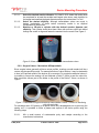
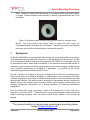
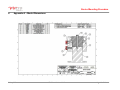
Standard moulding jig components for devices are shown coloured in Figure 4. Dimensions of
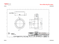
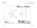
the standard moulding jig can be found in Appendix A. The jig components can be separated
and adjusted by loosening bolt A and thumb screws C & D.
The custom pedestal (Light GREY) is attached to the base (PURPLE) with a bolt (A). The
pedestal can be a Delrin™ insert or a replica of the outer dimensions of the device. See Section
5.2 for details on creating a device replica.
Figure 4. Components of the ViVitro Labs Standard Holder Moulding jig.
5.1. Holders With a Step
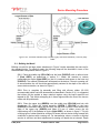
Insert E (Dark GREY), seen in Figure 4, is removable. This insert controls the height of the
ViVitro Labs Standard Holder, as seen in Figure 5. This height can be adjusted to accommodate
6 May 2015
© ViVitro Labs Inc. 2015
Page 6 of 19