1
Device Mounting Procedure
5.2.2.2.
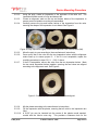
Using the putty, create an impression of the perimeter of the valve cuff. The
impression should consist of a top and bottom half.
Create an alignment mark on the top and bottom halves of the impression to
ensure correct orientation once they are assembled.
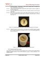
Carefully remove the top and bottom halves of the impression from the valve
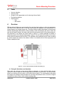
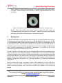
ensuring the shape of the impression is not altered. See Figure 8.
5.2.2.3.
5.2.2.4.
Figure 8. Putty impression (right) formed from Hancock II 505 CINCH valve (left).
5.2.2.5.
5.2.2.6.
5.2.2.7.
Allow the putty to cure according to the manufacturer’s instructions.
Once cured, test fit the valve into the two impression halves with the alignment
marks lined up to ensure proper fit. If the fit is not acceptable, repeat the
moulding procedure in steps 5.2.2.1. - 5.2.2.5. above.
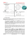
If the fit is acceptable, remove the valve from the two impression halves. Mate
the two cured impression halves together, ensuring the two halves are aligned
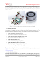
according to the alignment mark. See Figure 9.
Figure 9. Cured putty impression halves mated and aligned.
5.2.2.8.
5.2.2.9.
5.2.2.10.
6 May 2015
Mix the plaster according to the manufacturer’s instructions.
Fill the impression with the plaster, ensuring that all voids in the impression are
filled.
A 0.150” pin may be inserted into the centre of the plaster mould mandrel,
coaxial with the valve’s outer ring. This provides a clearance hole for the
© ViVitro Labs Inc. 2015
Page 9 of 19