1
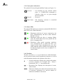
Frequency Converter
type Vacon NX for
Alimak’s Hoists and Lifts
User’s Manual
This manual is only applicable if the manufacturing number indicated below corresponds to the manufacturing number stamped on the identification
sign of the equipment. Where there is a conflict contact your ALIMAK representative.
Manufacturing No.:
Year:
If the bottom right corner of this book is cut, the book is only valid for illustrative use!
Part No. 9081536 - 1 01
2004 - 09 - 23
Photographs and drawings are illustrative only and do not necessarily show the design of the products on the market at any given point in time.
The products must be used in conformity with applicable practice and safety regulations. Specifications of the products and equipment
presented herein are subject to change without notice.
A0
ALIMAK NX FREQUENCY CONVERTER
1. SAFETY................................................... A1 – A2
1.1 WARNINGS ................................................................ A1
1.2 SAFETY INSTRUCTIONS......................................... A1
1.3 EARTHING AND EARTH FAULT PROTECTION.. A2
1.4 RUNNING THE MOTOR ........................................... A2
2. GENERAL............................................... A3 – A4
2.1 INSTRUCTIONS FOR INSTALLATION .....................
2.2 INSTRUCTIONS FOR INSULATION CHECKS .........
2.2.1 Motor cable insulation checks .................................
2.2.1 Mains cable insulation checks .................................
2.2.1 Motor insulation checks ...........................................
3
4
4
4
4
3. CONTROL KEYPAD........................... A4 – A18
3.1 INDICATIONS ON THE KEYPAD DISPLAY ............ 5
3.1.1 Drive status indication ............................................. 5
3.1.2 Control place indications ......................................... 6
3.1.3 Status LEDs.............................................................. 6
3.1.4 Text lines................................................................... 6
3.2 KEYPAD PUSH-BUTTONS ........................................ 7
3.2.1 Button descriptions................................................... 7
3.3 NAVIGATION ON THE CONTROL KEYPAD........... 8
3.3.1 Monitoring menu (M1)........................................... 10
3.3.2 Parameter menu (M2) ............................................ 11
3.3.3 Active faults menu (M4) ......................................... 13
3.3.4 Fault types.............................................................. 14
3.3.5 Fault codes ............................................................. 14
3.3.6 Fault time data record............................................ 15
3.3.7 Fault history menu (M5) ........................................ 15
3.3.8 System menu (M6) .................................................. 16
3.3.9 Copy parameters .................................................... 18
4. FAULT TRACING.............................. A19 – A23
4.1 VERIFYING THE PULSE ENCODER
FUNCTION /DIRECTION .......................................... 23
ALIMAK 34848 - 1/01
A1
SAFETY
ONLY A COMPETENT ELECTRICIAN MAY CARRY
OUT THE ELECTRICAL INSTALLATION / SERVICE
1.1 Attention
– The components of the power unit of the frequency
converter are live when Vacon NX is connected to mains
potential. Coming into contact with this voltage is
extremely dangerous and may cause death, or severe
injury. The control unit is isolated from the potential.
– The motor terminals U, V, W and the DC-link/brake resistor
terminals – / + are live when Vacon NX is connected to
mains, even if the motor is not running.
i4
– The control I/O-terminals are isolated from the mains
potential. However, the relay outputs and other I/Oterminals may have a dangerous control voltage present
even when Vacon NX is disconnected from mains.
– The frequency converter has a large capacitive leakage
current.
– Only spare parts delivered by Vacon must be used.
f4
1.2 Safety instructions
– The Vacon NX frequency converter is meant for fixed
installations only.
– Do not perform any measurements when the frequency
converter is connected to the mains.
– After disconnecting the frequency converter from the mains,
wait until the fan stops and the indicators on the keypad go
out (if no keypad is attached see the indicators on the cover).
Wait 5 more minutes before doing any work on Vacon NX
connections. Do not even open the cover before this time
has expired.
– Do not perform any voltage withstand tests on any part of
Vacon NX. There is a certain procedure according to which
the tests shall be performed. Ignoring this procedure may
result in damaged product.
– Prior to measurements on the motor or the motor cable,
disconnect the motor cable from the frequency converter.
– Do not touch the IC-circuits on the circuit boards. Static
voltage discharge may damage the components.
– Before connecting the frequency converter to mains make
sure that theVacon NX front and cable covers are closed.
ALIMAK 34849 - 1/01
A2
Earth = Ground
1.3 Earthing and earth fault protection
The Vacon NX frequency converter must always be earthed
with an earthing conductor connected to the earthing terminal.
The earth fault protection inside the frequency converter
protects only the converter itself against earth faults in the
motor, or the motor cable.
Due to the high capacitive currents present in the frequency
converter, fault current protective switches may not function
properly. If fault current protective switches are used they must
be tested with the drive with earth fault currents that are
possible to arise in fault situations.
1.4 Running the motor
Warning symbols
For your own safety, please pay special attention to the
instructions marked with the following
symbols:
ALIMAK 34850 - 1/01
A3
2. General
The VFC unit feeds a variable frequency to the motor(s) to give
a stepless speed control of the hoist/lift. In order to keep the
same motor torque the VFC also controls the output voltage to
the motor(s). The VFC unit is specially designed for Alimak
hoist/lift application, both hardware and software.
The VFC-unit has special software developed for use with
Alimak hoists and cannot be replaced with another VFC-unit.
2.1 Instructions for installation of VFC-hoist
Following procedure is valid for installation of Alimak VFChoists, which are erected for the first time or erected after being
moved from one site to another. This procedure must be
followed before the hoist can be used either in normal
or Inspection mode.
The hoists can handle all voltages in their range, but certain
measures must be taken.
Procedure:
1. Make sure that you have the relevant parameter list for the
actual lift/hoist. This is supplied within the electrical
documentation.
2. Put the main switch on the M- and B-panel in the off
position.
3. Connect the incoming power to the B-panel.
4. Measure the incoming voltage in the B-panel (after eventual
step-up or step–down trafo).
5. Check that the connections P1 – P8 on the primary side of
the control transformer in the M-panel, (also B-panel if
equipped with control transformer), correspond to the
incoming voltage. If not, adjust the connections according to
the chart on the transformer/electrical drawings.
6. Energize the M-panel by switching on the main switches on
the B- and M-panel.
7. If the VFC unit has been replaced with a spare unit, check
all parameters according to the relevant parameter list. See
section 3 for procedure.
ALIMAK 34851 - 1/01
A4
2.2 Instructions for insulation checks of VFC-hoist
2.2.1 Motor cable insulation checks
Disconnect the motor cable from terminals U, V and W of the
frequency converter and from the motor. Measure the insulation
resistance of the motor cable between each phase conductor, as
well as between each phase conductor and the protective ground
conductor. The insulation resistance must be >1MΩ.
2.2.2 Mains cable insulation checks
Disconnect the mains cable from terminals L1, L2 and L3 of the
frequency converter and from the mains. Measure the insulation
resistance of the mains cable between each phase conductor, as
well as between each phase conductor and the protective ground
conductor. The insulation resistance must be >1MΩ.
2.2.3 Motor insulation checks
Disconnect the motor cable from the motor and open the
bridging connections in the motor connection box. Measure the
insulation resistance of each motor winding. The measurement
voltage must be equal with at least the motor nominal voltage,
but not exceed 1000 V. The insulation resistance must be >1MΩ.
3. CONTROL KEYPAD
The control keypad is the link between the Vacon frequency
converter and the user. The Vacon NX control keypad features
an alphanumeric display with seven indicators for the Run
status (RUN,
, READY, STOP, ALARM, FAULT) and
three indicators for the control place (I/O term/ Keypad/BusComm).
There are also three Status Indicator LEDs (green - green - red),
see below.
The control information, i.e. the number of menu, description of
menu or the displayed value and the numeric information are
presented on three text lines.
The frequency converter is operable through the nine pushbuttons of the control keypad.
Furthermore, the buttons serve the purposes of parameter
setting and value monitoring.
The keypad is detachable and isolated from the input line
potential.
ALIMAK 34852 - 1/01
A5
3.1 Indications on the Keypad display
Figure 3 – 1. Vacon control keypad and drive status indications
3.1.1 Drive status indications
The drive status indications tell the user what the status of the
motor and the drive is and whether the motor control software
has detected irregularities in motor or frequency converter
functions.
RUN
= Motor is running; Blinks when the stop
command has been given but the frequency
is still ramping down.
= Indicates the direction of motor rotation.
STOP
= Indicates that the drive is not running.
READY = Lights when AC power is on. In case of a
trip, the symbol will not light up.
ALARM = Indicates that the drive is running outside a
certain limit and a warning is given.
FAULT = Indicates that unsafe operating conditions
were encountered due to which the drive was
stopped.
ALIMAK 34853 - 1/01
A6
3.1.2 Control place indications
The symbols I/O term, Keypad and Bus/Comm (see Figure 3–1)
I/O term
= I/O terminals are the selected control
place; i.e. START/STOP commands or
reference values etc. are given through
the I/O terminals.
Keypad
= Not used.
Bus/Comm = The frequency converter is controlled
through a fieldbus.
3.1.3 Status LEDs
The status LEDs light up in connection with the READY, RUN
and FAULT drive status indicators.
= Illuminates with the AC power connected to the
drive. Simultaneously, the drive status indicator
READY is lit up.
= Illuminates when the drive is running. Blinks
when the STOP button has been pushed and the
drive is ramping down.
= Illuminates when unsafe operating conditions
were encountered due to which the drive was
stopped (Fault Trip). Simultaneously, the drive
status indicator FAULT blinks on the display and
the fault description can be seen, see chapter 3.3.3,
Active Faults.
3.1.4 Text lines
The three text lines (•, ••, •••) provide the user with information
on his present location in the keypad menu structure, as well as
with information related to the operation of the drive.
= Location indication; displays the symbol and number
of menu, parameter etc. Example: M2 = Menu 2
(Parameters); P2.1.3 = Acceleration time
= Description line; Displays the description of menu,
value or fault.
= Value line; Displays the numerical and textual values
of references, parameters etc. and the number of
submenus available in each menu
ALIMAK 34854 - 1/01
A7
3.2 Keypad push-buttons
The Vacon alphanumeric control keypad features 9 pushbuttons that are used for the control of the frequency converter
(and motor), parameter setting and value monitoring.
Figure 3 – 2. Keypad push-buttons
3.2.1 Button descriptions
= This button is used to reset active faults (see
Chapter 3.3.3).
= This button is used to switch between two latest
displays. May be useful when you want to see
how the changed new value influences some
other value.
= The Enter button serves for:
1) confirmation of selections
2) fault history reset (2…3 seconds)
= Browser button up
Browse the main menu and the pages of
different submenus. Edit values.
= Browser button down
Browse the main menu and the pages of
different submenus. Edit values.
= Menu button left
Move backward in menu.
Move cursor left (in parameter menu).
Exit edit mode.
Hold down for 2…3 seconds to return to main
menu.
ALIMAK 34855 - 1/01
A8
= Menu button right
Move forward in menu. Move cursor right (in
parameter menu).
Enter edit mode.
= Start button. (Not normally used for Start in
Alimak application)
= Stop button. (Not normally used for Stop in
Alimak application)
3.3 Navigation on the control keypad
The data on the control keypad are arranged in menus and
submenus. The menus are used for example for the display and
editing of measurement and control signals, parameter settings
(chapter 3.3.2), reference values and fault displays (chapter
3.3.3).
The first menu level consists of menus M1 to M7 and is called
the Main menu. The user can navigate in the main menu using
the Browser buttons up and down. The desired submenu can be
entered from the main menu using the Menu buttons. When
there are still pages to enter under the currently displayed menu
or page, you can see an arrow in the lower right corner of the
display and by pressing the Menu button right, you can reach
the next menu level.
The control keypad navigation chart is shown on the next page.
Please note that the menu M1 is located in the lower left corner.
From there you will be able to navigate your way up to the
desired menu using the menu and browser buttons.
ALIMAK 34856 - 1/01
A9
Figure 3 - 3. Keypad navigation chart
ALIMAK 34857 - 1/01
A 10
3.3.1 Monitoring menu (M1)
You can enter the Monitoring menu from the Main menu by
pushing the Menu button right when the location indication M1
is visible on the first line of the display. How to browse through
the monitored values is presented in Figure 3-4.
The monitored signals carry the indication V#.# and they are
listed in Table 3-1. The values are updated once every 0.3
seconds.
This menu is meant only for signal checking. The values cannot
be altered here. For changing values of parameters see Chapter
3.3.2.
Figure 3 - 4. Monitoring menu
Code
Signal name
Unit
Description
V1.1
Output frequency
Hz
V1.2
Frequency reference
Hz
V1.3
Motor speed
rpm
Calculated motor speed
V1.4
Motor current
A
Measured motor current
V1.5
Motor torque
%
Calculated actual torque/nominal torque of the unit
V1.6
Motor power
%
Calculated actual power/nominal power of the unit
V1.7
Motor voltage
V
Calculated motor voltage
V1.8
DC-link voltage
V
Measured DC-link voltage
V1.9
Unit temperature
ºC
Heat sink temperature
V1.10
Voltage input
V
AI1
V1.11
Current input
mA
V1.12
DIN1, DIN2, DIN3
Digital input statuses
V1.13
DIN4, DIN5, DIN6
Digital input statuses
V1.14
DO1, RO1, RO2
Digital and relay output statuses
V1.15
Analogue output current
mA
AO1
V1.15
Encoder speed
rpm
Encoder speed in rpm
M1.17
Multimonitoring items
Frequency to the motor
AI2
Displays three selectable monitoring values.
Table 3-1. Monitored signals
ALIMAK 34858 - 1/01
3.3.2 Parameter menu (M2)
Parameters are the way of conveying the commands of the user
to the frequency converter. The parameter values can be edited
by entering the Parameter Menu from the Main Menu when the
location indication M2 is visible on the first line of the display.
The value editing procedure is presented in Figure 3-5.
Push the Menu button right once to move into the Parameter
Group Menu (G#). Locate the parameter group desired by using
the Browser buttons and push the Menu button right again to
enter the group and its parameters. Use again the Browser
buttons to find the parameter (P#) you want to edit. From here
you can proceed in two different ways: Pushing the Menu
button right takes you to the edit mode. As a sign of this, the
parameter value starts to blink. You can now change the value
in two different manners:
1 Just set the new desired value with the Browser buttons and
confirm the change with the Enter button. Consequently, the
blinking stops and the new value is visible in the value field.
2 Push the Menu button right once again. Now you will be
able to edit the value digit by digit.
This editing manner may come in handy, when a relatively
greater or smaller value than that on the display is desired.
Confirm the change with the Enter button.
ALIMAK 34859 - 1/01
A 11
A 12
The value will not change unless the Enter button is pushed.
Pressing the Menu button left takes you back to the previous
menu.
Several parameters are locked, i.e. uneditable, when the drive is
in RUN status. If you try to change the value of such a
parameter the text *Locked* will appear on the display. The
frequency converter must be stopped in order to edit these
parameters.
You can return to the Main menu anytime by pressing the Menu
button left for 1 – 2 seconds.
Once in the last parameter of a parameter group, you can move
directly to the first parameter of that group by pushing the
Browser button up.
Figure 3 – 5. Parameter value change procedure
ALIMAK 34860 - 1/01
A 13
3.3.3 Active faults menu (M4)
The Active faults menu can be entered from the Main menu by
pushing the Menu button right when the location indication M4
is visible on the first line of the keypad display.
When a fault brings the frequency converter to a stop, the
location indication F1, the fault code, a short description of the
fault and the fault type symbol (see Chapter 3.3.4) will appear
on the display. In addition, the indication FAULT or ALARM
(see Figure 3 – 1 or Chapter 0) is displayed and, in case of a
FAULT, the red led on the keypad starts to blink. If several
faults occur simultaneously, the list of active faults can be
browsed with the Browser buttons.
The memory of active faults can store the maximum of 10 faults
in the order of appearance. The display can be cleared with the
Reset button and the read-out will return to the same state it was
before the fault trip. The fault remains active until it is cleared
with the Reset button, or with a reset signal from the I/O
terminal.
Note ! Remove external Start signal before resetting the fault to
prevent unintentional restart of the drive.
3.3.4 Fault types
In the NX frequency converter, there are four different types of
faults. These types differ from each other on the basis of the
subsequent behaviour of the drive. See Table 3 – 2.
Figure 3 - 6. Fault display
ALIMAK 34861 - 1/01
A 14
Fault type
symbol
Meaning
A (Alarm)
This type of fault is a sign of an unusual operating
condition. It does not cause the drive to stop, nor
does it require any special actions. The 'A fault'
remains in the display for about 30 seconds.
F (Fault)
An 'F fault' is a kind of fault that makes the drive
stop. Actions need to be taken in order to restart the
drive.
AR (Fault
Autoreset)
If an 'AR fault' occurs the drive will also stop
immediately. The fault is reset automatically and the
drive tries to restart the motor. Finally, if the restart is
not successful, a fault trip (FT, see below) occurs.
FT (Fault Trip)
If the drive is unable to restart the motor after an AR
fault an FT fault occurs. The effect of the 'FT fault' is
basically the same as that of the F fault: the drive is
stopped.
Table 3 - 2. Fault types
3.3.5 Fault codes
The fault codes, their causes and correcting actions are
presented in the table last in this manual.
3.3.6 Fault time data record
When a fault occurs the information described above in 3.3.3 is
displayed. By pushing the Menu button right here you will enter
the Fault time data record menu indicated by T.1 T.13. In this
menu, some selected important data valid at the time of the fault
are recorded. This feature is intended to help the user or the
service person to determine the cause of fault.
The data available are:
T.1
Counted operation days
(Fault 43: Additional code)
T.2
Counted operation hours
(Fault 43: Counted operation days)
hh:mm:ss
(d)
T.3
Output frequency
(Fault 43: Counted operation hours)
Hz
(hh:mm:ss)
T.4
Motor current
A
T.5
Motor voltage
V
T.6
Motor power
%
T.7
Motor torque
%
T.8
DC voltage
V
T.9
Unit temperature
°C
T.10
Run status
T.11
Direction
T.12
Warnings
T.13
0-speed*
ALIMAK 34862 - 1/01
d
A 15
Real time record
If real time is set to run on the frequency converter the data
items T1 and T2 will appear as follows:
T.1
Counted operation days
yyyy-mm-dd
T.2
Counted operation hours
hh:mm:ss,sss
3.3.7 Fault history menu (M5)
The Fault history menu can be entered from the Main menu by
pushing the Menu button right when the location indication M5
is visible on the first line of the keypad display.
All faults are stored in the Fault history menu in which you can
browse through them using the Browser buttons. Additionally,
the Fault time data record pages (see Chapter 3.3.6) are
accessible at each fault. You can return to the previous menu
anytime by pushing the Menu button left.
The memory of the frequency converter can store a maximum
of 30 faults in the order of appearance. The number of faults
currently in the fault history is shown on the value line of the
main page (H1 H#). The order of the faults is indicated by the
location indication in the upper left corner of the display. The
latest fault carries the indication F5.1, the second latest F5.2 etc.
If there are 30 uncleared faults in the memory the next
occurring fault will erase the oldest from the memory.
Pressing the Enter button for about 2 to 3 seconds resets the
whole fault history. Then, the symbol H# will change to 0.
Figure 3-7. Fault history menu
ALIMAK 34863 - 1/01
A 16
3.3.8 System menu (M6)
The System menu can be entered from the main menu by
pushing the Menu button right when the location indication M6
is visible on the display.
The controls associated with the general use of the frequency
converter, such as parameter sets or information about the
hardware and software are located under the System menu. The
number of submenus and subpages is shown with the symbol S
(or P) on the value line.
Functions in the System menu
Code
Function
Min
Max
Unit
Default
Selections
S6.1
Language selection
English
English
S6.2
Application selection
S6.3
Copy parameters
S6.3.1
Parameter sets
Store set 1
Load set 1
Store set 2
Load set 2
Load factory defaults
S6.3.2
Load up to keypad
All parameters
S6.3.3
Load down
from keypad
All parameters
All but motor parameters
Application parameters
P6.3.4
Parameter backup
S6.4
Compare parameters
S6.5
Security
Alimak Lift
No
Alimak Lift
Yes
No
S6.5.1
Password
Not used
0=Not used
P6.5.2
Parameter lock
Change
Enabled
S6.5.3
Start-up wizard
Change Enabled
Change Disabled
No
Yes
S6.5.4
Multimonitoring items
S6.6
Keypad settings
P6.6.1
Default page
P6.6.2
Default page/
Operating menu
P6.6.3
Timeout time
0
65535
P6.6.4
Contrast
0
31
P6.6.5
Backlight time
S6.7
Hardware settings
P6.7.1
Internal brake resistor
P6.7.2
Fan control
P6.7.3
HMI acknowledg.timeout
P6.7.4
HMI number of retries
Change Enabled
Change Disabled
Always 65535 min
s
30
18
10
Not connected
Temperature
200
5000
1
10
ms
ALIMAK 34864 - 1/01
200
5
Not connected
Connected
Continuous
Temperature
A 17
Code
Function
S6.8
System information
S6.8.1
Total counters
C6.8.1.1
MWh counter kWh
C6.8.1.2
Power On day counter
C6.8.1.3
Power On hours counter hh:mm:ss
S6.8.2
Trip counters
T6.8.2.1
MWh counter kWh
T6.8.2.2
Clear MWh trip counter
T6.8.2.3
Operating days trip counter
T6.8.2.4
Operating hour trip counter
T6.8.2.5
Clear operating time counter
S6.8.3
Software info
S6.8.3.1
Software package
S6.8.3.2
System software version
S6.8.3.3
Firmware interface
S6.8.3.4
System load
S6.8.4
Applications
S6.8.4.1
Name of application
Min
Max
Unit
Default
hh:mm:ss
D6.8.4.#.1 Application ID
D6.8.4.#.2 Applications Version:
D6.8.4.#.3 Applications: Firmware interface
S6.8.5
Hardware
I6.8.5.1
Info: Unit power
kW
I6.8.5.2
Info: Unit voltage
V
I6.8.5.3
Info: Brake chopper
I6.8.5.4
Info: Brake resistor
S6.8.6
Expander boards
S6.8.7
Debug
S6.8.9
Debug Power
S6.8.11
Debug Power
ALIMAK 34865 - 1/01
Selections
A 18
3.3.9 Copy parameters
The parameter copy function is used when the operator wants to
copy one or all parameter groups from one drive to another. All
the parameter groups are first uploaded to the keypad, then the
keypad is connected to another drive and then the parameter
groups are downloaded to it (or possibly back to the same
drive).
Before any parameters can successfully be copied from one
drive to another the drive has to be stopped when the parameters are downloaded to it:
The parameter copy menu (S6.3) embodies four functions:
Parameter sets (S6.3.1)
The Vacon NX frequency converter features a possibility for the
user to load back the factory default parameter values and to
store and load two customized parameter sets (all parameters
included in the application). Alimak default parameter set is
stored as Set1.
On Parameter sets page (S6.3.1), push the Menu button right to
enter the Edit menu. The text LoadFactDef begins to blink and
you can confirm the loading of factory defaults by pushing the
Enter button. The drive resets automatically. Alternatively you
can choose any other of the storing or loading functions with
the Browser buttons.
Confirm with the Enter button. Wait until 'OK' appears on the
display.
ALIMAK 34866 - 1/01
A 19
4. FAULT TRACING
When a fault is detected by the frequency converter control
electronics, the drive is stopped and the symbol F together with
the ordinal number of the fault, the fault code and a short fault
description appear on the display. The fault can be reset with the
Reset button on the control keypad or via the I/O terminal. The
faults are stored in the Fault history menu (M5) which can be
browsed. The different fault codes you will find in the table
below.
The fault codes, their causes and correcting actions are
presented in the table below. The shadowed / yellow faults are
A faults only. The items written in white on black background
present faults for which you can program different responses in
the application. See parameter group Protections.
Note: When contacting distributor or factory because of a fault
condition, always write down all texts and codes on the keypad
display.
ALIMAK 34867 - 1/01
f1
A 20
Fault
code
Fault
Possible cause
Correcting measures
1
Overcurrent
Frequency converter has detected too high
a current (>4*IH) in the motor cable:
– sudden heavy load increase
– short circuit in motor cables
– unsuitable motor
Check loading.
Check motor.
Check cables.
2
Overvoltage
The DC-link voltage has exceeded the
limits defined.
– too short a deceleration time
– high overvoltage spikes in supply
Make the deceleration time longer.
Use brake chopper or brake resistor
(available as options)
3
Earth fault
Current measurement has detected that the Check motor cables and motor.
sum of motor phase current is not zero.
– insulation failure in cables or motor
5
Charging switch
The charging switch is open, when the
START command has been given.
– faulty operation
– component failure
6
Emergency stop
Stop signal has been given from the option
board.
7
Saturation trip
Various causes:
– defective component
– brake resistor short-circuit or overload
Cannot be reset from the keypad.
Switch off power.
DO NOT RE-CONNECT POWER !
Contact factory.
If this fault appears simultaneously
with Fault 1, check motor cables
and motor.
8
System fault
– component failure
– faulty operation
Note exceptional fault data record, see
3.3.6.
Reset the fault and restart.
Should the fault re-occur, contact the
distributor near to you.
9
Undervoltage
DC-link voltage is under the voltage limits
defined in.
– most probable cause: too low a supply
voltage
– frequency converter internal fault
In case of temporary supply voltage
break reset the fault and restart the
frequency converter. Check the
supply voltage. If it is adequate, an
internal failure has occurred.
Contact the distributor near to you.
10
Input line
supervision
Input line phase is missing.
Check supply voltage and cable.
11
Output phase
supervision
Current measurement has detected that
there is no current in one motor phase.
Check motor cable and motor.
12
Brake chopper
supervision
– no brake resistor installed
– brake resistor is broken
– brake chopper failure
Check brake resistor.
If the resistor is ok, the chopper is
faulty. Contact the distributor near
to you
13
Frequency converter Heatsink temperature is under –10°C
undertemperature
.
ALIMAK 34868 - 1/01
Reset the fault and restart.
Should the fault re-occur, contact the
distributor near to you.
Check Panel heater.
A 21
Fault
code
Fault
Possible cause
Correcting measures
14
Frequency converter Heatsink temperature is over 90°C (or
overtemperature
77ºC, NX_6, FR6).
Overtemperature warning is issued when
the heatsink temperature exceeds 85°C
(72ºC).
Check the correct amount and flow
of cooling air.
Check the heatsink for dust.
Check the ambient temperature.
Make sure that the switching
frequency is not too high in relation
to ambient temperature and motor load.
15
Motor stalled
Motor stall protection has tripped.
Check motor.
16
Motor overtemperature
Motor overheating has been detected by
frequency converter motor temperature
model. Motor is overloaded.
Decrease the motor load.
If no motor overload exists, check
the temperature model parameters.
17
Motor underload
Motor underload protection has tripped.
22
EEPROM
checksum fault
Parameter save fault
23
FAULT
– faulty operation
– component failure
24
Counter fault
Values displayed on counters are incorrect
25
Microprocessor
watchdog fault
– faulty operation
– component failure
Reset the fault and restart.
Should the fault re-occur, contact the
distributor near to you.
26
Start-up prevented
Start-up of the drive has been prevented.
Cancel prevention of start-up.
29
Thermistor fault
The thermistor input of option board has Check motor cooling and loading
detected increase of the motor
Check thermistor connection
temperature
(If thermistor input of the option
board is not in use it has to be short
circuited).
31
IGBT temperature
(hardware)
IGBT Inverter Bridge overtemperature
protection has detected too high a short
term overload current
32
Fan cooling
Cooling fan of the frequency converter
Contact the distributor near to you.
does not start, when ON command is given.
34
CAN bus
communication
Sent message not acknowledged.
Ensure that there is another device
on the bus with the same configuration.
36
Control unit
NXS Control Unit can not control NXP
Power Unit and vice versa
Change control unit
37
Device changed
(same type)
Option board or control unit changed.
Same type of board or same power rating
of drive.
Reset
Note: No fault time data record!
38
Device added
(same type)
Option board or drive added.
Drive of same power rating or same type
of board added.
Reset
Note: No fault time data record!
39
Device removed
Option board removed.
Drive removed.
Reset
Note: No fault time data record!
ALIMAK 34869 - 1/01
Check loading.
Check motor size.
A 22
Fault
code
Fault
Possible cause
Correcting measures
40
Device unknown
Unknown option board or drive.
Contact the distributor near to you.
41
IGBT temperature
IGBT Inverter Bridge over temperature
protection has detected too high a short
term overload current
Check loading.
Check motor size.
42
Brake resistor
over temperature
Brake resistor over temperature protection has detected too heavy braking
Set the deceleration time longer.
Use external brake resistor.
43
Encoder fault
Note the exceptional Fault data record.
See 3.3.6. Additional codes:
1 = Encoder 1 channel A is missing
2 = Encoder 1 channel B is missing
3 = Both encoder 1 channels are missing
4 = Encoder reversed
Check encoder channel connections.
Check the encoder board.
44
Device changed
(different type)
Option board or control unit changed.
Option board of different type or different
power rating of drive.
Reset
Note: No fault time data record!
Note: Application parameter
values restored to default.
45
Device added
(different type)
Option board or drive added.
Option board of different type or drive of
different power rating added.
Reset
Note: No fault time data record!
Note: Application parameter
values restored to default.
50
Analogue input
Iin < 4mA (sel.
signal range 4
to 20 mA)
Current at the analogue input is < 4mA.
– control cable is broken or loose
– signal source has failed
Check the current loop circuitry.
51
External fault
Digital input fault.
52
Keypad
The connection between the control keycommunication fault pad and the frequency converter is broken.
Check keypad connection and
possible keypad cable.
53
Fieldbus fault
The data connection between the fieldbus
Master and the fieldbus board is broken
Check installation.
If installation is correct contact the
nearest distributor.
54
Slot fault
Defective option board or slot
Check board and slot.
Contact the nearest distributor.
56
PT100 board
temp. fault
Temperature limit values set for the PT100
board parameters have been exceeded
Find the cause of temperature rise
80
Brake
supervision
External brake supervision signal has not
been activated after the brake open
signal is activated P2.7.24.
81
Brake logic
supervision
Brake open signal has not been activated after
defined time after run request P2.7.25
82
Under current
Motor current is less than set limit parameter
P2.7.29
83
Shaft speed
Shaft speed from encoder differs from the
calculated shaft speed P2.7.30.
ALIMAK 34870 - 1/01
A 23
Verifying the Pulse encoder function /direction
– Set the lift/hoist in Inspection mode
– Go to Parameter P 2.6.1. The setting should read "CL
SpeedCtrl", which means Closed Loop Speed Control
– Set the parameter P 2.6.1 to "OL Speed Cont", which means
Open Loop Speed Control.
– Go to Monitor V 1.16 Encoder Speed.
– When you run the lift/hoist in the Up direction you should
get a positive rpm value (for instance + 400). When you run
the lift/hoist in the Down direction, you should get a
negative rpm value (for instance -400). The actual rpm value
depends on the motor rpm (speed).
– Return the Parameter setting of P 2.6.1 to "CL SpeedCtrl".
In case you don't get a value other than 0 when you run the
lift/hoist, check the encoder connections. Try again. If you still
don't get a value other than 0, the pulse encoder probably is
broken. You have to replace it.
If you get a negative value when going upwards and a positive
value going downwards, check the encoder connections.
You probably have switched the A and B pulses.
ALIMAK 34871 - 1/01