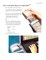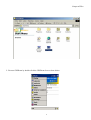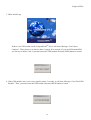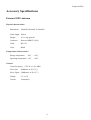
1
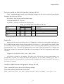
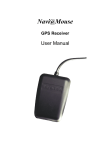
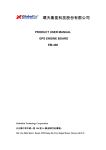
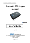
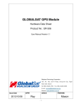
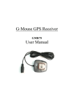
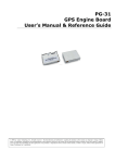
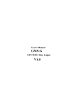
TM CompactGPS User Manual CompactGPSTM Contents CompactGPSTM at A Glance 2 About CompactFlashTM 3 What Is CompactGPSTM? 3 What Have Inside the Package? 4 What Is GPS? 4 Description of the interfaces 4 How to Install & Operate CompactGPSTM 5 How to Install & Operate CompactGPSTM 6 How to Test Your CompactGPSTM 7 Specifications 12 Accessory Specifications 13 Software Data 14 How to enable Push To Fix function 17 Troubleshooting 21 1 CompactGPSTM CompactGPSTM at A Glance External Antenna Connector Reset Button LED Internal GPS Antenna 2 CompactGPSTM About CompactFlashTM The CompactFlashTM Association (CFA) was established in October 1995 with the premise that CompactFlashTM (CF) technology would enable the introduction of a new class of advanced, small lightweight, low power mobile products that would significantly increase the productivity and enhance the lifestyles of millions of people. The concept behind CF technology was simple: to capture, retain and transport data, audio and images on CompactFlashTM Storage Cards. CF Storage Cards provided the capability to easily transfer all types of digital information and software between a large variety of digital systems. The CFA approved and published the CompactFlashTM standard. This vendor-independent specification enabled users to develop CF products that function correctly and are compatible with future CF designs, eliminating compatibility issues. Now the CFA has developed the CF+ specification to expand the CF concept beyond flash data storage and include I/O devices and magnetic disk data storage. The CF+ specification also includes the original Type I (3.3mm thick) card and newer Type II (5mm thick) cards. While CompactFlashTM and many I/O devices can fit into the Type I card, the Type II cards enable higher capacity CompactFlashTM cards, magnetic disk cards and many additional I/O cards. What Is CompactGPSTM? CompactGPSTM introduces a GPS module in CompactFlashTM interface. CompactGPSTM represents the latest ingenious GPS technology from the leading GPS receiver manufacturer. Inserting it and implementing a map or navigation software, CompactGPSTM will convert the compatible devices for GPS functions, such as locate one or multiple objects, conduct personal & vehicle navigation, and / or apply for geographical surveys. 3 CompactGPSTM What Have Inside the Package? Before you start up, make sure that your package includes the following items. If any items are missing or damaged, contact your dealer immediately. Please refer to the contact information on the last page of this manual. ◆ GPS Receiver ◆ User Manual CD ◆ External Antenna (Option) ◆ Warranty Card What Is GPS? In 1974 the USA Department of Defense set about developing a Global Positioning System (GPS), a constellation of 24 satellites that Orbits 12,000 miles above the Earth. Using triangulation of signals from four of the satellites, a receiving unit on earth can pinpoint its current location to within a few meters. A GPS device receives the GPS data from satellites and then converts the GPS data into longitude, latitude, and altitude (LLA) data, velocity, time and etc. Position and navigation information is vital to a wide range of professional and recreational activities covering surveying, search and rescue, tracking, hiking, navigating, and so forth. Description of the interfaces LED Function LED off LED on LED flashing GPS receiver switch off GPS receiver searching signal GPS signal is fixed. Reset Button When push the Reset button, it will initialize and restart the CompactGPSTM system. External Antenna Connector/External GPS antenna This connector is designed for external GPS antenna. Please refer the Accessory Specifications for detail descriptions and specification of external antenna. When to use the External Antenna When you are in a car, or any environments that GPS signal is blocked, the external GPS antenna will help to receive better GPS signal. Please place the external GPS antenna in an outdoor open-space to ensure a better GPS performance. 4 CompactGPSTM How to use the External Antenna Plug the reversed MMCX connector of the external antenna to the jack on CompactGPSTM. Place the external antenna on the roof of the car or an outdoor open-space, and make sure place it in correct direction. That is, the side with magnetic is the bottom side, and the upper side must face to sky in order to receive better signal reception. External Antenna Connector Reversed MMCX Connector Antenna (upper side) Magnet (bottom side) Cable Reversed MMCX Connector 5 CompactGPSTM How to Install & Operate CompactGPSTM The CompactGPSTM supports plug and play. 1.If your PDA or laptop have CompactFlashTM slot just plug your CompactGPSTM into the slot. 2.If you don’t have the CompactFlashTM slot but you got a PCMCIA slot, then you can apply a adapter to connect your CompactGPSTM to PCMCIA slot. Note: 1.In order to see NMEA0183 navigational data, use the Hyper Terminal program of Windows 95/98. Please setup the COM port connected with CompactGPSTM to: Baud rate: 4800 Data bit: 8 Parity: None Stop bit: 1 Flow control: None. 2.Refer to NMEA 0183 data format. 6 CompactGPSTM How to Test Your CompactGPSTM Install Guide: 1. Copy GPSDemo.exe from PC to your Pocket PC. (1) Install Microsoft ActiveSync to your PC. Refer to your Pocket PC manual for installation procedure. (2) Setup your Pocket PC cradle to Desktop PC UART port. The Microsoft ActiveSync will detect your Pocket PC automatically. (3) After finish the connection between PC and the Pocket PC. Copy GPSDemo.exe file to the target path: \Mobile Device\My Pocket PC\windows\Start Menu. ActiveSync will automatically transfer to Pocket PC 7 CompactGPSTM 8 CompactGPSTM 2. Execute GPSDemo by double click the GPSDemo Icon as show below. 9 CompactGPSTM 3. Show initial Logo If there is no GPS module on the CompactFlashTM slot, it will show Message “Can’t Open Comport”. Then, please try to choose other Comport, (For example :If you use HP Jornada PDA you can try to choose Com 2) you must insert the GPS module and enter OPEN button to restart. 4. If the GPS module can’t receive any signal in about 5 seconds, it will show Message “Can’t Find GPS Module”. Then, you must insert the GPS module and enter OPEN button to restart. 10 CompactGPSTM 5. If everything is ok, it will show the satellite diagram like below. Push the ok button on title bar will terminate the program. Enter the “Position” Button will change to Position diagram 6. Position Diagram will show the position. Enter ok button can return to the satellite diagram. Push Cold St. button can clear the GPS module data and initialize GPS data receiving. 11 CompactGPSTM Specifications Physical characteristics Dimension Weight 48mm(W) * 103.5mm(L) * 33mm(H) 65 grams Temperature characteristics Storage temperature: Operating temperature: -20℃ ~ + 65℃. 0℃ ~ + 55℃. General Sensitivity -135 dBm Channels 12 channels L1 1575.42 MHz. C A code 1.023MHz chip rate. Accuracy Position accuracy:10m, 95% Velocity accuracy:0.1 meters / second without SA Time accuracy:1 microsecond synchronized to GPS time. Datum WGS-84. Position update period Every 1 second Dynamic conditions Altitude:18000 meters (60000 feet) max. Velocity:515 meters / second max. Acceleration:4 G, max. Jerk:20 meters / second3, max. Power It shall use the following power Full/Max current Trickle/Min current Typical current :DC 3.3V ± 10 % :160mA :35mA :80mA 12 CompactGPSTM Accessory Specifications External GPS Antenna Physical characteristics Dimensions 45mm(W)*45mm(L)*15mm(H) Cable length 500cm Weight 110 ± 10g (typical) Connector Reversed MMCX (180°) Cable RG-174 Color Black Temperature characteristics Storage temperature: -40℃ ~ +85℃ Operating temperature: -30℃ ~ +80℃ General Center Frequency 1575.42 ± 1.023 MHz LNA Gain 26dB(min, at 25±15℃) Noise Figure 2.0dB(max, at 25±15℃) Voltage 3.3 ±0.3V Current 12mA(max) 13 CompactGPSTM Software Data NMEA V2.2 Protocol It is the compact flash interface NMEA Output Messages The CompactGPSTM outputs the following messages as shown in Table 1: NMEA Record GGA GSA GSV RMC Table 1 NMEA Output Messages Description Global positioning system fixed data GNSS DOP and active satellites GNSS satellites in view Recommended minimum specific GNSS data GGA-Global Positioning System Fixed Data Table 2 contains the values of the following example: $GPGGA, 161229.487, 3723.2475, N, 12158.3416, W, 1, 07, 1.0, 9.0, M, , , ,0000*18 Name Message ID UTC Position Latitude N/S Indicator Longitude E/W Indicator Position Fix Indicator Satellites Used HDOP MSL Altitude Units Geoid Separation Units Age of Diff. Corr. Diff. Ref. Station ID Checksum <CR><LF> Table 2 GGA Data Format Example Units Description $GPGGA GGA protocol header 161229.487 hhmmss.sss 3723.2475 ddmm.mmmm N N=north or S=south 12158.3416 dddmm.mmmm W E=east or W=west 1 See Table 2-1 07 Range 0 to 12 1.0 Horizontal Dilution of Precision 9.0 meters M meters meters M meters second Null fields when DGPS is not used 0000 *18 End of message termination 14 CompactGPSTM Table 2-1 Value 0 1 2 3 Position Fix Indicator Description Fix not available or invalid GPS SPS Mode, fix valid Differential GPS, SPS Mode, fix valid GPS PPS Mode, fix valid GSA-GNSS DOP and Active Satellites Table 3 contains the values of the following example: $GPGSA, A, 3, 07, 02, 26, 27, 09, 04, 15, , , , , , 1.8,1.0,1.5*33 Name Message ID Mode 1 Mode 2 Satellite Used1 Satellite Used1 …. Satellite Used1 PDOP HDOP VDOP Checksum <CR><LF> Table 3 GSA Data Format Example Units Description $GPGSA GSA protocol header A See Table 3-2 3 See Table 3-1 07 Sv on Channel 1 02 Sv on Channel 2 …. Sv on Channel 12 1.8 Position Dilution of Precision 1.0 Horizontal Dilution of Precision 1.5 Vertical Dilution of Precision *33 End of message termination Table 3-1 Value 1 2 3 Mode 1 Description Fix not available 2D 3D Table 3-2 Value M Mode 2 Description Manual-forced to operate in 2D or 3D mode Automatic-allowed to automatically switch 2D/3D A 15 CompactGPSTM GSV-GNSS Satellites in View Table 4 contains the values of the following example: $GPGSV, 2, 1, 07, 07, 79, 048, 42, 02, 51, 062, 43, 26, 36, 256, 42, 27, 27, 138, 42*71 Name Message ID Number of Messages1 Messages Number1 Satellites in View Satellite ID Elevation Azimuth SNR (C/No) …. Satellite ID Elevation Azimuth SNR (C/No) Checksum <CR><LF> Table 4 Example $GPGSV 2 1 07 07 79 048 42 27 27 138 42 *71 GSV Data Format Units Description GSV protocol header Range 1 to 3 Range 1 to 3 degrees degrees dBHz degrees degrees dBHz Channel 1(Range 1 to 32) Channel 1(Maximum 90) Channel 1(True, Range 0 to 359) Range 0 to 99, null when not tracking …. Channel 4(Range 1 to 32) Channel 4(Maximum 90) Channel 4(True, Range 0 to 359) Range 0 to 99, null when not tracking End of message termination RMC-Recommended Minimum Specific GNSS Data Table 5 contains the values of the following example: $GPRMC, 161229.487, A, 3723.2475, N, 12158.3416, W, 0.13, 309.62, 120598, ,*10 Name Message ID UTC Position Status Latitude N/S Indicator Longitude E/W Indicator Speed Over Ground Course Over Ground Date Magnetic Variation Checksum <CR><LF> Table 5 RMC Data Format Example Units Description $GPRMC RMC protocol header 161229.487 hhmmss.sss A A=data valid or V=data not valid 3723.2475 ddmm.mmmm N N=north or S=south 12158.3416 dddmm.mmmm W E=east or W=west 0.13 knots 309.62 degrees True 120598 ddmmyy degrees E=east or W=west *10 End of message termination 16 CompactGPSTM How to enable Push To Fix function 1. Switch the communication protocol from NMEA to SIRF binary 2. Enable PTF function 3. Switch back to NMEA protocol with the output rate as following: GPGGA 1/s GPGSA 1/s GPGSV 5/s GPRMC 1/s Set SIRF protocol at NMEA protocol This command message is used to set the protocol (SiRF Binary or NMEA) and/or the communication parameters (baud rate, data bits, stop bits, parity). Generally, this command is used to switch the module back to SiRF Binary protocol mode where a more extensive command message set is available. When a valid message is received, the parameters are stored in battery-backed SRAM and then the Evaluation Unit restarts using the saved parameters. Table 6 contains the input values for the following example: Switch to SIRF Binary protocol at 9600,8,N,1 $PSRF100,0,9600,8,1,0*0C Table 6 Set Serial Port Data Format Name Example Units Description Message ID $PSRF100 PSRF100 protocol header Protocol 0 0=SiRF Binary, 1=NMEA Baud 9600 4800,9600,19200,38400 Data Bits 8 8,71 Stop Bits 1 0,1 Parity 0 0=None ,1=Odd,2=Even Checksum *0C <CR><LF> End of message termination 1 SiRF protocol is only valid for 8data bits, 1 stop bit, and no parity. 17 CompactGPSTM Protocol to enable the Push To Fix function---Message I.D. 151 Table 7 contains the input values for the following example: Sets the receiver into low power Modes. Example: Set receiver to PTF off. A0A20009—Start Sequence and Payload Length 97000000C8000000C8—Payload 0227B0B3—Message Checksum and End Sequence Table 7 Set Trickle Power Parameters I.D. 151 Binary(Hex) Name Bytes Scale Example Units Description Message ID 1 97 ASCII 151 Push To Fix Mode 2 0000 ON=1, OFF=0 Duty Cycle 2 *10 00C8 % % Time on Milli Seconds On 4 000000C8 ms Range 200 ~ 500 ms Time Payload Length: 9bytes. Push-to-Fix In this mode the receiver will turn on every 30 minutes to perform a system update consisting of a RTC calibration and satellite ephemeris data collection if required (i.e., a new satellite has become visible) as well as all software tasks to support SnapStart in the event of an NMI. Ephemeris collection time in general this takes 18 to 30 seconds. If ephemeris data is not required then the system will re-calibrate and shut down. In either case, the amount of time the receiver remains off will be in proportion to how long it stayed on: Off period = (On Period*(1-Duty Cycle) / Duty Cycle) Off Period is limited to 30 minutes. The duty cycle will not be less than approximately On Period/1800, or about 1%. Push-to-Fix keeps the ephemeris for all visible satellites up to date so position/velocity fixes can generally be computed within SnapStart times (when requested by the user) on the order of 3 seconds. Switch To NMEA Protocol at Sirf protocol– Message I.D. 129 Table 8 contains the input values for the following example: Request the following NMEA data at 9600 baud: GGA – ON at 1 sec, GLL – 1sec, GSA – ON at 1 sec GSV – ON at 1 sec, RMC – 1 sec, VTG – 1 sec 18 CompactGPSTM Example: A0A20018 – Start Sequence and Payload Length 8102010100010501050100010001000100010001000112C0 – Payload 0164B0B3 – Message Checksum and End Sequence Name Bytes Message ID 1 Mode 1 GGA Message1 1 2 Checksum 1 GLL Message 1 Checksum 1 BSA Message 1 Checksum 1 GSV Message 1 Checksum 1 RMC Message 1 Checksum 1 VTG Message 1 Checksum 1 Unused Field 1 Unused Field 1 Unused Field 1 Unused Field 1 Unused Field 1 Unused Field 1 Unused Field 1 Unused Field 1 Baud Rate 1 Payload Length: 24bytes Table 8 Switch To NMEA Protocol Binary(Hex) Units Description Scale Example 81 ASCII 129 02 01 1/s 01 00 1/s 01 05 1/s 01 05 1/s 01 00 1/s 01 00 1/s 01 00 Recommended value 01 Recommended value 00 Recommended value 01 Recommended value 00 Recommended value 01 Recommended value 00 Recommended value 01 Recommended value 12C0 38400,19200,9600,4800,2400 A value of 0x00 implies NOT to send message, otherwise data is sent at 1 message every X seconds requested (i.e., to request a message to be sent every 5 seconds, request the message using a value of 0x05.)Maximum rate is 1/255s. A value of 0x00 implies the checksum is NOT calculated OR transmitted with the message (not recommended). A value of 0x01 will have a checksum calculated and transmitted as part of the message (recommended). After the CompactGPSTM enter the sleep mode, user can get a fast navigation solution by pressing the Wake Up Button (Reset button). 19 CompactGPSTM 20 CompactGPSTM Troubleshooting Problem No position output but timer is counting Execute Fail Can’t Open COM port Reason Weak or no GPS signal can be received at the place CompactGPSTM is. At outdoor space but GPS signal is blocked by buildings Solution Connect an external antenna which locate at a outdoors open space to your CompactGPSTM and then press Reset Button. Go outdoors and press Reset Button to try again, or connect an external antenna to improve the poor GPS signal. Wrong CPU Type Pocket PC support multiple types of CPU. Make sure you download the correct software. (You can use ‘setting’ function of start menu on your PDA to check the correct CPU type) TM Insert CompactFlashTM or Close all other The CompactFlash is not inserted or some other application applications that using the COM port. is using the COM port. Poor connection Check the CompactFlashTM is inserted correctly. Can’t Find GPS Module No signal No action for few minutes may cause Pocket PC enters power saving mode. It will close the COM port at the same time. Close the application and execute it again to reopen the COM port. Weak or no GPS signal when using Connect an external antenna to your CompactGPS indoors. CompactGPSTM and place it at an outdoors open space, then press Reset button. 21