1
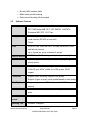
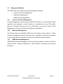
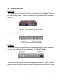
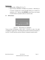
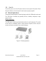
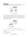
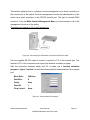
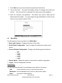
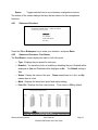
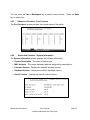
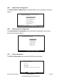
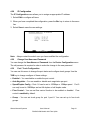
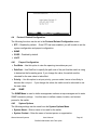
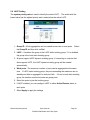
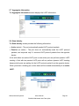
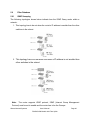
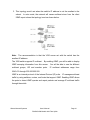
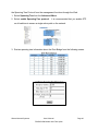
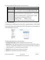
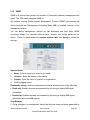
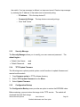
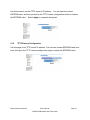
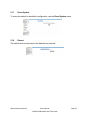
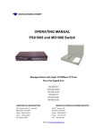
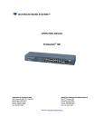
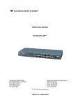
12 OPERATING MANUAL PSX1008 and MS1008 Switch Managed Switch with Eight 10/100Base-TX Ports Plus One Fiber Port PSX1008-MSC PSX1008-MST PSX1008-MTRJ PSX1008-SSC-30 MS1008-MSC MS1008-MST MS1008-MTRJ MS1008-SSC-30 CORPORATE HEADQUATERS MANUFACTURING/CUSTOMER SERVICE 5001 American Blvd. W., Suite 605 945 37 Avenue, NW Bloomington, MN 55437 Rochester, MN 55901 Phone: 800.441.5319 Phone: 800.328.2275 Phone: 952.831.5603 Phone: 507.252.1951 Fax: 952.831.5605 th Fax: 507.285.1952 Web site: http://www.watersnet.com Table of Contents 1.0 Specifications ...............................................................................................5 2.0 Package Contents ........................................................................................7 3.0 Introduction ..................................................................................................7 3.1 Hardware Features........................................................................................ 8 3.2 Software Features ......................................................................................... 9 3.3 Management Methods................................................................................. 10 3.31 Console and Telnet Management ............................................................... 10 3.32 Web-based Management ............................................................................ 10 3.33 SNMP Network Management ...................................................................... 10 3.4 Hardware Description .................................................................................. 11 3.5 LED Indicators............................................................................................. 12 3.6 Desktop Installation ..................................................................................... 13 3.61 Attaching Rubber Feet ................................................................................ 13 3.62 Power On .................................................................................................... 14 4.0 Network Applications.................................................................................14 4.1 Network Configuration ................................................................................. 15 4.2 Main Menu................................................................................................... 17 4.21 Status and Counters.................................................................................... 18 4.22 Status and Counters - Port Status............................................................... 18 4.23 Status and Counters - Port Counters .......................................................... 19 4.24 Status and Counters - System Information.................................................. 19 4.25 Switch Static Configuration.......................................................................... 19 4.25 Switch Static Configuration.......................................................................... 20 4.26 Administration Configuration ....................................................................... 20 4.27 Device Information ...................................................................................... 20 4.28 IP Configuration........................................................................................... 21 4.29 Change User Name and Password ............................................................. 21 4.30 Port / Trunk Configuration ........................................................................... 21 4.31 Port Mirroring Configuration ........................................................................ 22 4.32 VLAN Configuration..................................................................................... 23 Waters Network Systems User’s Manual PSX/MS1008 Models with Fiber Uplink Page 2 4.33 Creating a VLAN Group............................................................................... 23 4.34 Edit / Delete a VLAN Group......................................................................... 24 4.35 Priority Configuration ................................................................................... 24 4.36 MAC Address Configuration ........................................................................ 25 4.37 Filtering MAC Addresses............................................................................. 27 4.38 Misc. Configuration...................................................................................... 27 4.38.1 Port Security ............................................................................................ 28 4.38.2 MAC Age Interval..................................................................................... 28 4.38.3 Broadcast Storm Filtering ........................................................................ 29 4.38.4 Max Bridge Transmit Delay...................................................................... 29 4.4 Protocol Related Configuration.................................................................... 30 4.41 Perport Configuration .................................................................................. 30 4.42 SNMP .......................................................................................................... 30 4.43 System Options ........................................................................................... 30 4.44 Community Strings ...................................................................................... 31 4.45 Trap Managers ............................................................................................ 31 4.45 GVRP .......................................................................................................... 31 4.46 LACP ........................................................................................................... 31 4.46.1 Aggregator Setting................................................................................... 31 4.46.2 State Activity ............................................................................................ 32 4.46.3 LACP Status ............................................................................................ 32 4.5 Reboot Switch ............................................................................................. 32 4.6 Xmodem Upgrade ....................................................................................... 32 5.0 Web-Based Management ...........................................................................32 5.1 Accessing Management Functions through the Web .................................. 33 5.2 Web Management Home Overview............................................................. 33 5.3 Port Status................................................................................................... 33 5.4 Port Statistics .............................................................................................. 34 5.5 Administrator ............................................................................................... 34 5.6 LACP Setting............................................................................................... 38 5.7 Aggregator Information................................................................................ 39 Waters Network Systems User’s Manual PSX/MS1008 Models with Fiber Uplink Page 3 5.8 State Activity................................................................................................ 39 5.9 Filter Database ............................................................................................ 40 5.91 IGMP Snooping ........................................................................................... 40 5.92 Static MAC Address .................................................................................... 42 5.93 Port Security................................................................................................ 42 5.94 MAC Address Filtering................................................................................. 43 5.95 VLAN Configuration..................................................................................... 43 5.96 Basic VLAN Setting ..................................................................................... 44 5.10 Spanning Tree............................................................................................. 45 5.11 Port Mirroring............................................................................................... 48 5.12 SNMP .......................................................................................................... 49 5.13 Security Manager ........................................................................................ 50 5.14 TFTP Update Firmware ............................................................................... 50 5.15 Configuration Backup .................................................................................. 50 5.16 TFTP Backup Configuration ........................................................................ 51 5.17 Reset System .............................................................................................. 52 5.18 Reboot......................................................................................................... 52 6.0 Troubleshooting .........................................................................................53 6.1 Before Calling for Assistance ...................................................................... 53 6.2 Return Material Authorization (RMA) Procedure ......................................... 54 6.3 Shipping and Packaging Information........................................................... 55 7.0 Warranty......................................................................................................56 Waters Network Systems User’s Manual PSX/MS1008 Models with Fiber Uplink Page 4 1.0 Specifications OPERATIONAL CHARACTERISTICS: MAC Address Table: Switching Mode: Memory Buffer Size: Performance: 8k Store-and-forward 4Mb Non-blocking wire speed (up to 3.8Gbps) MANAGEMENT FEATURES: Web-based, Telnet and console SNMP Port setting for duplex and speed Port trunking (4 groups) Port based and tagged VLANs (up to 256) QoS IGMP GVRP Port mirroring Broadcast storm Spanning Tree NETWORK STANDARDS: IEEE 802.3 IEEE 802.3u IEEE 802.3x IEEE 802.1q IEEE 802.1p IEEE 802.1d IEEE 802.3ad EMI/SAFETY COMPLIANCE: FCC Class A, CE, UL cUL NETWORK CABLE CONNECTORS RJ45 shielded female ports 10/100Mbps: CAT5 UTP or better Multimode: SC Singlemode: SC connectors (up to 10km) POWER SUPPLY: Waters Network Systems User’s Manual PSX/MS1008 Models with Fiber Uplink Page 5 Input Voltage 110 to 240 VAC, 50 to 60Hz Power Consumption 17 watts maximum OPERATING ENVIRONMENT: Ambient Temperature: 32° to 113°F (0° to 45°C) Storage: -40° to 158°F (-40°to 70°C) Ambient relative humidity: 10% to 90% (non-condensing) MECHANICAL: Enclosure: Rugged high-strength sheet metal suitable for stand-alone, wall or tabletop mounting Cooling Method: Fan cooled PHYSICAL CHARACTERISTICS: PSX Models: Dimensions: 10 x 5.25 x 1.75 in (250 x 132 x 37.5mm) Weight: 2.4lbs MS Models: Dimensions: 16 x 11 x 1.75 in (406x 279 x 37.5mm) Weight: 3.7lbs (1.68kg) Waters Network Systems User’s Manual PSX/MS1008 Models with Fiber Uplink Page 6 2.0 Package Contents Examine the shipping container for obvious damage prior to installing this product. Notify the carrier of any damage that you believe occurred during shipment. Ensure that the items listed below are included. If an item is missing, please contact your supplier. The 1008 switch package contains the following: 1008 Switch Power Cord Four Rubber Feet RS-232 cable User’s Guide 3.0 Introduction In our modern society, communication and sharing information is essential to our lives. Computer networks have proven to be one of the fastest methods of communication. The 1008 series of switches are compact desktop size switches that are the ideal solution for any network user. The 1008 switches provide high-performance managed switching functions with low-cost connectivity. The 1008 switches feature store-and-forward switching and will auto-learn and store source addresses with an 8K-entry MAC address table. Figure 3-1. PSX-1008-MSC The switch provides eight switched auto-sensing 10/100Base-TX RJ45 ports plus one 100Base-FX fiber port. The switch will automatically detect the speed of connected devices to accommodate both 10 and 100Mbps. The 10Mbps bandwidth will accommodate 10Mbps workgroup switches while simultaneously providing the 100Mbps bandwidth required for multimedia applications. All RJ45 ports support the Auto MDI/MDIX function. Waters Network Systems User’s Manual PSX/MS1008 Models with Fiber Uplink Page 7 With the built-in Web-based management functionality, managing and configuring the switch is easy. From cabinet management to port-level control and monitoring, you can visually configure and manage your network via your Web Browser. Just click your mouse instead of typing command strings. The 1008 switch can be managed via Telnet, Console, or SNMP Management. Ethernet switching technology dramatically boosted the total bandwidth of a network, eliminating congestion problems inherent with the carrier sense multiple access with the collision detection (CSMA/CD) protocol and greatly reduced unnecessary transmissions. This revolutionized networking. First, by allowing two-way, simultaneous transmissions over the same port (full-duplex), bandwidth was essentially doubled. Second, by reducing the collision domain to a single switch-port, the need for carrier sensing was eliminated. Third, by using the store-and-forward technology’s approach of inspecting each packet to intercept corrupt or redundant data, switching eliminated unnecessary transmissions that slow down network traffic. Auto-negotiation regulates the speed and duplex of each port, based on the capability of both devices. Flow-control allows transmission from a 100Mbps node to a 10Mbps node without loss of data. Auto-negotiation and flow-control may have to be disabled for some networking operations that involve legacy equipment. Disabling the auto-negotiation is accomplished by hard setting the speed or duplex mode of a port. 3.1 Hardware Features Conforms to IEEE 802.3, 802.3u, and 802.3x Ethernet Standards Auto-sensing 10/100Base-TX RJ45 port ports Automatic MDI/MDIX crossover for each 10/100Base-TX port 1 Fixed 100Base-FX port (SC, ST or MTRJ connector) Console port on rear side for system configuration Half-duplex mode for backpressure Full-duplex for flow control Store-and-forward switching architecture Automatic address learning, address migration Waters Network Systems User’s Manual PSX/MS1008 Models with Fiber Uplink Page 8 8K-entry MAC address table 2Mbit memory buffer sharing Performs non-blocking full wire speed 3.2 Software Features RFC Standard RFC 1157 SNMP, RFC 1213 MIB II, RFC 1643 Ethernet Like, RFC 1493 Bridge MIB, RFC 1757 RMON1, LANTECH Enterprise MIB, RFC 1215 Trap Management Web management (IE) Local console (RS-232 on rear side) Telnet Trunk IEEE 802.3ad Trunk with LACP for load distribution control and fail over recover Up to 4 ports per group, maximum 4 groups Class of Service IEEE802.1p, Each port supports 2 priority queues (high/low) QoS System support 8 levels of priority and mapping to high/low priority queue VLAN Port-based VLAN, 802.1Q Tag VLAN, Protocol type VLAN VLAN ID up to 4094, VLANs up to 256 groups. GVRP support. IP Multicast Support IGMP snooping, supports 256 groups. Support 2 types of query mode (enable/disable or auto query) Filter Database Support per port static MAC address lock, MAC filter, port security Port Mirror Use this feature to analyze port traffic. Supports maximum 8 ports. Broadcast None, 5%, 10%, 15%, 20%, 25% Control Spanning Tree Waters Network Systems IEEE802.1d support User’s Manual PSX/MS1008 Models with Fiber Uplink Page 9 3.3 Management Methods The 1008 switch series supports following management methods: Console and Telnet Management Web-based Management SNMP Network Management 3.31 Console and Telnet Management Console Management is done through the RS-232 Console Port. Use the RS-232 cable supplied in your package to connect directly to a workstation from your 1008 switch. Once an IP address has been set on the 1008 switch, you can use Telnet or Web Management to login to the switch and modify the configuration. 3.32 Web-based Management The 1008 provides an embedded HTML web site residing in flash memory. It offers advanced management features and allow users to manage the switch from anywhere on the network through a standard browser such as Microsoft Internet Explorer. 3.33 SNMP Network Management SNMP (Simple Network Management Protocol) provides a means to monitor and control network devices, manage configurations, collect statistics, performance and security information. Waters Network Systems User’s Manual PSX/MS1008 Models with Fiber Uplink Page 10 3.4 Hardware Description Front Panel The front panel of the 1008 switch consists of 8 auto-sensing 10/100Mbps RJ45 ports and one 100Base-FX port. The LED indicators are also located on the front panel of the switch. Figure 3-2. The Front Panel of the 1008-MSC Switch The front panel is displayed as below. Figure 3-3. Front Panel of the 1008-MSC Switch Rear Panel The console port and a three-pronged AC power plug are located on the rear panel of the switch. The 1008 switches work in the range 100-240V AC, 50-60Hz. Figure 3-4. The Rear Panel of the 1008 Switch The console port can be used to perform management functions. Console connection requires a direct connection between the switch and an workstation with a RS-232 cable. Waters Network Systems User’s Manual PSX/MS1008 Models with Fiber Uplink Page 11 Hardware Ports One port either 1000Base-SX, LX or TX Eight 10/100 auto MDI/MDIX 10/100Base-TX connections. MDI allows you to connect to another hub or switch and MDIX allows you to connect to a workstation or PC. Therefore, Auto MDI/MDIX means that you can connect to another switch or workstation without a crossover cable. 3.5 LED Indicators Figure 3-5. LED Indicators for 1008 Switch There are three LED-Indicators (100M, LK/ACT, FDX/COL) for each of the eight 10/100Base-TX copper ports. The following table provides the status and description of the LEDs. The LEDs provide a real-time indication of systematic operation status. Waters Network Systems User’s Manual PSX/MS1008 Models with Fiber Uplink Page 12 Ethernet Port LED Status Color Description Power On Green Power On On Green The port is operating at 100Mbps. 100M LNK/ ACT FDX/ COL Off Port is operating at 10Mbps or no device attached On Green The port is connecting with the device. Blinks Green The port is receiving or transmitting data. Off No device attached. On Orange The port is operating in full-duplex mode. Blinks Orange Collision of packets occurs in the port. Off No device attached or in half-duplex mode. Table 3-1. LED Description 3.6 Desktop Installation Choose a surface for your switch that is clean, smooth, level, sturdy and with a power outlet nearby. Make sure there is enough clearance around the switch to allow attachment of cables, power cord and air circulation. 3.61 Attaching Rubber Feet 1. Make sure mounting surface on the bottom of the switch is free of grease and dust. 2. Remove adhesive backing from the rubber feet. 3. Apply the rubber feet to each corner on the bottom of the switch. Figure 3-6. Attaching Rubber Feet to each corner on the bottom of the switch Waters Network Systems User’s Manual PSX/MS1008 Models with Fiber Uplink Page 13 3.62 Power On Connect the power cord to the AC power socket on the rear panel of the switch. Check the power indicator on the front panel to see if power is properly supplied. 4.0 Network Applications This section provides samples of network topology in which the 1008 switch can be used. The 1008 series of switches are generally used as a desktop, workgroup or edge segment switch. Desktop Application The 1008 series of switches provide the ideal solution for small workgroups. The switch can be used as a standalone switch to which personal computers, servers, and print servers are directly connected to form a small workgroup. Figure 4-1. Desktop Application Waters Network Systems User’s Manual PSX/MS1008 Models with Fiber Uplink Page 14 Segment Application For enterprise networks where large data packets are constantly processed, this switch is suitable for department users to connect to the corporate backbone. Figure 4-2 Segment Application The 1008 switch can be directly connected to PCs, workstations, and servers. The switch automatically learns node addresses, which are subsequently used to filter and forward all traffic based on the destination address. You can use any of the copper ports to connect with another switch to interconnect each of your small-switched workgroups to form a larger switched network. Figure 4-3 Use fiber port to extend the distance between workgroups In the above illustration, two 1008 switches are used to interconnect two small workgroups. 4.1 Network Configuration Waters Network Systems User’s Manual PSX/MS1008 Models with Fiber Uplink Page 15 This section explains how to configure console management via a direct connection to the console port of the switch. Console management involves the administration of the switch via a direct connection to the RS-232 console port. This port is a female DB-9 connector. From the Main Console Management Menu, you have access to all of the management functions of the switch. Connecting a Terminal or PC to the Console Port Figure 4-4. Connecting the 1008 switch to a terminal via RS-232 cable Use the supplied RS-232 cable to connect a terminal or PC to the console port. The terminal or PC to be connected must support the terminal emulation program. After the connection between switch and PC is made, run a terminal emulation program or Hyper Terminal to match the following default characteristics of the console port: Baud Rate: 9600 bps Data Bits: 8 Parity: None Stop Bit: 1 Flow Control: None Figure 4-5. Communication Parameters Waters Network Systems User’s Manual PSX/MS1008 Models with Fiber Uplink Page 16 1. Press Enter once you have entered the parameters listed above. 2. Turn on the switch. The switch will display a series of messages as it performs a self test. Once the self test is completed, the login screen will be displayed. 3. Enter the username and password. The default user name is root, and the default password is root. You may change the login identification to make it more secure for your network (Section 4.29). 4.2 Main Menu The following five choices are listed on the Main Menu: Status and Counters – Displays the status of the switch. Switch Static Configuration - Use to configure the switch from another set of menus. Protocol Related Configuration - Configure the following protocol functions. o STP o SNMP o GVRP o LACP Reboot Switch - Restart the system or reset switch to default configuration. Logout - Exit the management functions. Control Keys The following keys are used to move between menu options in all menus: Tab: Use the tab key to move to the next menu option. Backspace: Use the backspace key to move to the previous option. Enter: Use enter to make selection Waters Network Systems User’s Manual PSX/MS1008 Models with Fiber Uplink Page 17 Space: Toggles selected item to move between configuration choices. The bottom of the screen displays the keys that are used to for the management functions. 4.21 Status and Counters Press the Tab or Backspace key to make your selection, and press Enter. 4.22 Status and Counters - Port Status The Port Status’ screen displays the status of all of the ports. Type - Displays the port speed for each port. Enabled – You have the choice of enabling or disabling the port. Enabled will be displayed as Yes and Disabled will be displayed as No. The Default setting is Yes. Status - Display the status of the port. Down means there is no link, and Up means there is a link. Mode - Displays the actual port speed and duplex setting. Flow Ctrl - Displays the flow control status. Flow control is ON by default. Waters Network Systems User’s Manual PSX/MS1008 Models with Fiber Uplink Page 18 You can press the Tab or Backspace key to select a menu choice. Press the Enter key to select item. 4.23 Status and Counters - Port Counters The Port Counters’ screen provides the current status of the switch 4.24 Status and Counters - System Information The System Information screen displays the following information: System Description - The name of device type. MAC Address - The unique hardware address assigned by manufacturer. Firmware Version - Displays the switch’s firmware version. Hardware Version - Displays the switch’s hardware version. Kernel Version – Displays the switch’s kernel version. Waters Network Systems User’s Manual PSX/MS1008 Models with Fiber Uplink Page 19 4.25 Switch Static Configuration The Switch Static Configuration (on the Main Menu) menu provides the following options: 4.26 Administration Configuration The Administration Configuration (from the Switch Configuration menu) menu provides the following options: 4.27 Device Information The Device Information menu provides the following information: Waters Network Systems User’s Manual PSX/MS1008 Models with Fiber Uplink Page 20 4.28 IP Configuration The IP Configuration menu allows you to assign an appropriate IP address. 1. Select Edit to configure all items. 2. When you have completed the configuration, press the Esc key to return to the menu line. 3. Select Save to save the new settings. Note: 4.29 Always restart the switch once you have modified the configuration. Change User Name and Password You can change the User Name and Password from the Device Configuration menu. The old password is required in order to make the change to the new password. 4.30 Port / Trunk Configuration You can use this menu to change the port status and configure trunk groups. Use the TAB key to change configure of these settings: Enabled – You can disable or enable the port control. Auto Negotiate – You can enable or disable auto negotiation per port. Speed/Duplex Config – Ports 1-8 can be set to 100Mbps or 10Mbps speed. Port 9 can only be set to 1000Mbps and set full-duplex or half-duplex mode. Flow Control – You can set flow control function to be enabled or disabled. Flow control is enabled by default. Group – You can set trunk group for port 1~port 8. You can set up to four trunk groups. Waters Network Systems User’s Manual PSX/MS1008 Models with Fiber Uplink Page 21 4.31 Port Mirroring Configuration Port mirroring is a method used for monitoring traffic in switched networks. Traffic can be monitored through ports by one specific port. The traffic that goes in or out monitored ports will be duplicated into the monitoring port. Port mirroring is disabled by default. Port Mirroring can be accessed from the Switch Static Configuration Menu. Port Mirroring State - Use the space bar to toggle from Disable to Enable for port-mirroring function. Mirroring Port - The mirror port can be used to see all monitored port traffic. Source Port - The source port is the port you want to monitor. All monitored port traffic will be copied to sniffed port. You can select a maximum of nine ports to monitor in the switch. User can choose to monitor RX frames only or TX frames only or both RX and TX frames from the port. Waters Network Systems User’s Manual PSX/MS1008 Models with Fiber Uplink Page 22 4.32 VLAN Configuration The VLAN Configuration Menu can be accessed from the Switch Static Configuration Menu. VLANs are disabled by default. Once you have enabled VLANs, you may choose between the following: 802.1q 802.1q with GVRP Port-based PVID (Port VID): Set the port VLAN ID that will be assigned to untagged traffic on a given port. This feature is useful for accommodating devices that you want to participate in the VLAN but that don’t support tagging. Only one untagged VLAN is allowed per port. Ingress Filter 1: Forward only packets with VIDs matching this port’s configured VID. Use the Space bar to choose to forward or drop the frame that the VID does not match this port’s configured VID. Ingress Filter 2: Drop untagged frame. Use the Space bar to choose drop or forward the untagged frame. Once you have set VLANs to enabled, you are ready to create a VLAN group. 4.33 Creating a VLAN Group 1. Select Create a VLAN Group from the VLAN Configuration Menu. 2. Provide the following information for the VLAN: VLAN Name: Type a name for the new VLAN. VLAN ID: Type a VID (between 2~4094). The default is 1. Protocol VLAN: Press the Space bar to choose the type of protocol. Waters Network Systems User’s Manual PSX/MS1008 Models with Fiber Uplink Page 23 4.34 Un-Tagged: Assign untagged to the port. Tagged: Assign tagged to the port. No: The port is not a member of this VLAN group. Edit / Delete a VLAN Group To edit or delete a VLAN group, use the following instructions. 1. Select Edit/Delete a VLAN Group from the VLAN Configuration Menu. 2. Choose the VLAN group that you want to edit or delete and then press Enter. 3. You can modify the configuration for the VLAN. 4. Remember to choose Save once you have completed your modifications or VLAN deletions so all configuration values are saved. Note: You cannot modify the default VLAN Name and VLAN ID, and you cannot delete the default VLAN. 4.35 Priority Configuration Levels 0~7 can be set to high or low queue service High/Low Queue Service Ratio H: L: User can select the ratio of high priority packets and low priority packets. o First In First Out: The sequence of packets sent depends on the order of arrival. o High to Low: The high priority packets are sent before low priority packets. o Ratio H: L: Select the preference given to packets in the switch's high-priority queue. These options represent the number of high priority packets sent before one low priority Waters Network Systems User’s Manual PSX/MS1008 Models with Fiber Uplink Page 24 packet is sent. For example, 2 High: 1 Low means that the switch sends two high priority packets before sending one low priority packet. Note: Remember to save settings.. 4.36 MAC Address Configuration When you add a static MAC address, it remains in the switch's address table, regardless of whether the device is physically connected to the switch. This saves the switch from having to re-learn a device's MAC address when the device is active again on the network. User can add / modify / delete a static MAC address. Add static MAC address 1. Select Add to add a static MAC address. 2. Enter the MAC address of the desired port. This port will be set to permanently forward traffic, regardless of the device’s network activity. 3. Enter the port number under Port num. Waters Network Systems User’s Manual PSX/MS1008 Models with Fiber Uplink Page 25 4. If tag-based VLANs are set up on the switch, static addresses are associated with individual VLANs. Type the VID to associate with the MAC address. 5. Press ESC to return to the action menu line. 6. Select Save to save all configure values. Edit Static MAC address 1. Select Edit to modify a static MAC address. 2. Choose the MAC address that you want to modify and then press Enter. 3. Select Edit to modify all the items. 4. Press ESC to return to the action menu line. 5. Select Save to save all configure values. Delete static MAC address 1. Select Delete to delete a static MAC address. 2. Select the MAC address that you want to delete and then press Enter. 3. After deleting a static MAC address, select Save to complete the deleting operation. Waters Network Systems User’s Manual PSX/MS1008 Models with Fiber Uplink Page 26 4.37 Filtering MAC Addresses Edit Filtering MAC Addresses 1. Select Edit to modify a static filtering address. 2. Choose the MAC address that you want to modify and then press Enter. 3. Press Edit to modify all the items. 4. Press ESC to return to the action menu line. 5. Select Save to save all configure values. Delete Filtering MAC Addresses 1. Press Delete to delete a Filtering MAC address. 2. Choose the MAC address that you want to delete and then press Enter. 3. After deleting the filtering MAC address, select Save to complete the deleting operation. 4.38 Misc. Configuration The following settings can be made through the Misc Configuration Menu: Port Security Waters Network Systems User’s Manual PSX/MS1008 Models with Fiber Uplink Page 27 MAC Age Interval Broadcast Storm Filtering Bridge Transmit Delay Bound 4.38.1 Port Security A port in security mode will be “locked” which means no new addresses can be learned. Only the incoming packets with SMAC already existing in the address table can be forwarded normally. User can disable the port from learning any new MAC addresses, and then use the static MAC addresses screen to define a list of MAC addresses that can communicate with the secure port. 1. Select Edit to enable or disable the port security. 2. Press the Space bar to choose enable / disable item. 3. Press ESC to return to the action menu line. 4. Select Save to save the configure values. 4.38.2 MAC Age Interval Use this option to enter the number of seconds that an inactive MAC address remains in the switch’s address table. The valid range is 300~765 seconds. Default is 300 seconds. Waters Network Systems User’s Manual PSX/MS1008 Models with Fiber Uplink Page 28 4.38.3 Broadcast Storm Filtering This option is used to configure the broadcast storm control. The valid threshold value is 5%, 10%, 15%, 20%, 25% and NO. 4.38.4 Max Bridge Transmit Delay Bridge transit delay bound must be enabled before you can configure this function. Max bridge transmit delay bound - Limit the packets’ queuing time in the switch. If enabled, packets that exceed the queue will be dropped. Valid values are 1 sec, 2 sec, 4 sec and Off. The default is 1 second. Enable Delay Bound - Limit the low priority packets queuing time in switch. If enabled, the low priority packet will be sent once it exceeds the Max Delay Time. Max Delay Time - Used to set the time that low priority packets are queued in switch. The valid range is 1~255 ms. Waters Network Systems User’s Manual PSX/MS1008 Models with Fiber Uplink Page 29 4.4 Protocol Related Configuration The following functions can be set in the Protocol Related Configuration menu: STP – Disabled by default. Once STP has been enabled, you will be able to set the system configuration and perport configuration. SNMP GVRP – Disabled by default. LACP 4.41 Perport Configuration PortState – Use this option to view the spanning tree status per port. PathCost – Use PathCost to specify the path cost of the port that the switch is using to determine the forwarding ports. If you change the value, the switch must be rebooted for the new value to take effect. Priority – Use this option to set port priority; you can make it more or less likely to become the root port. If you change the value, the switch must be rebooted to use the new value. 4.42 SNMP The SNMP Menu is used to define management stations as trap managers and to enter SNMP community strings. Use this menu to define a name, location, and contact person for the switch. 4.43 System Options The following settings can be made from the System Options Menu. System Name – Enter a name to be used for the switch. System Contact – Enter the name of contact person or organization. Waters Network Systems User’s Manual PSX/MS1008 Models with Fiber Uplink Page 30 System Location – Enter the location of the switch. 4.44 Community Strings Use the Community Strings Menu to enter the following information: Community Name - Enter the name of current strings. Write Access – Determine the rights. Choose between: o Read only - Read only enables requests accompanied by this string to display MIB-object information. o Read/Write – Read/write enables requests accompanied by this string to display MIB-object information and to set MIB objects. 4.45 Trap Managers A trap manager is a management station that receives traps or system alerts generated by the switch. If no trap manager is defined, no traps are received. To create a trap manager, enter the IP address of the station and a community string. 4.45 GVRP The GVRP Menu allows you to enable and disable the GVRP (VLAN Registration Protocol). 4.46 GVRP is disabled by default. LACP The LACP Configuration Menu provides the following options: Aggregator Setting State Activity LACP Status 4.46.1 Aggregator Setting Group: Display the trunk group ID. LACP: Use the Space bar to enable or disable LACP (Link Aggregation Control Protocol) support. If it is enabled, the group is LACP static trunking group. If it is disabled, the group is local static trunking group. LACP Work Port Num: This setting is the maximum number of ports that can be aggregated at the same time. If LACP is set to static trunking group, the additional ports are on standby and able to aggregate if a work port fails. If it is set to local static trunking group, the number must be the same as group ports. NOTE: Before setting LACP support, you have to set the trunk group. Waters Network Systems User’s Manual PSX/MS1008 Models with Fiber Uplink Page 31 4.46.2 State Activity Active: The port automatically sends LACP protocol packets. Passive: The port does not automatically send LACP protocol packets, and responds only when it receives LACP protocol packets from the opposite device. 4.46.3 LACP Status This screen provides the status of the LACP configuration. 4.5 Reboot Switch Rebooting the switch provides two choices. Default: Reset switch to recover default configuration. Restart: Reboot the switch with new configuration settings. 4.6 Xmodem Upgrade To perform the Xmodem upgrade, press the X key to start upgrading for Xmodem. Disconnect the terminal and modify baud rate to 57600bps. Then, reconnect. Once attached, follow these instructions: 1. Select send file under the transfer menu on the menu bar. 2. Select the browse button to select the path. 3. Select 1K Xmodem from protocol. 4. Select Send. 5. After successfully upgrading the new firmware, please modify baud rate to 9600bps. 5.0 Web-Based Management This section introduces the configuration and functions of the Web-based management of 1008 switch. The 1008 series of switches provides an embedded HTML website residing in flash memory. Management functions can be performed from anywhere on the network through a standard Web Browser. NOTE: If you are using Win2000 with the Service Pack 2 function, the web management function will be not be displayed correctly if the IE is below Version 5.5. Waters Network Systems User’s Manual PSX/MS1008 Models with Fiber Uplink Page 32 5.1 Accessing Management Functions through the Web In order to use the management functions via your Web Browser, the following defaults must be set. Use the Console connection to modify the IP for use with your web browser. IP Address: 192.168.16.1 Subnet Mask: 255.255.255.0 Default Gateway: 192.168.16.254 User Name: root Password: root Once these settings have been made, access your Web Browser and type in: http://192.168.16.1. 5.2 Enter the user name and password. Web Management Home Overview The opening screen will provide a picture of the switch at the top of the screen and menu options to the left of your screen. 5.3 Port Status The Port Status menu provides the following information: State: Displays the port status (ON or OFF depending on the user’s setting). Unlink will be treated as off. Link Status: Down is No Link. UP is Link. Auto Negotiation: Displays the auto negotiation mode. Is it set to auto negotiate or is it hard set to a speed. Speed Status: Current status of port Duplex Status: Display full-duplex or half-duplex mode. Flow Control: Waters Network Systems Displays the Flow Control current setting. User’s Manual PSX/MS1008 Models with Fiber Uplink Page 33 Config: Displays the state of user setting. Actual: Displays the negotiation result. 5.4 Port Statistics The following information provides a view of the current status of the unit. The following displays a single port counter: 5.5 Administrator The Administrator functions: IP address – You can modify the IP address from this option. You must reset the switch and use the new IP address to connect via your browser. Basic Switch settings – The following switch settings are displayed through this option: o Description – Displays the name of the device. o MAC Address – Displays the unique hardware address assigned by the manufacturer. This cannot be changed. o Firmware Version – Displays the switches firmware version. Waters Network Systems User’s Manual PSX/MS1008 Models with Fiber Uplink Page 34 o Hardware Version – Displays the switches firmware version. o Kernel Version – Displays the default EEPROM value. Advanced Switch Settings – The following switch settings are displayed through this option: o Miscellaneous Settings MAC Address Age-Out Time – Enter the number of seconds that an inactive MAC address remains in the switch’s address table. The valid range is 300 ~ 765 seconds. The default is 300 seconds. Max Bridge Transit Delay Bound Control – Limit the packets queuing time in the switch. If enabled, the packets exceeding the queue will be dropped. Valid values are 1, 2 or 4 seconds and Off. The default is 1 second. Broadcast Storm Filter - This option is used to configure the broadcast storm control. It must be enabled and then the upper threshold must be set for the individual ports. The threshold is the percentage of the port’s total bandwidth used by broadcast traffic. When the broadcast traffic for a port rises above the threshold that has been set, broadcast storm control becomes active. The valid threshold value is 5%, 10%, 15%, 20%, 25% and Off. o Priority Queue Service Settings First Come First Service - The sequence of packets sent depends on the arrival order. Waters Network Systems User’s Manual PSX/MS1008 Models with Fiber Uplink Page 35 All High before Low - The high priority packets are sent before the low priority packets. Weighted Round Ratio - Select the preference given to packets in the switch's high-priority queue. These options represent the number of high priority packets sent before one low priority packet is sent. For example, 2 High: 1 Low means that the switch sends 2 high priority packets before sending 1 low priority packet. Enable Delay Bound – This setting limits the low priority packets queuing time in switch. The Default Max Delay Time is 255ms. If the low priority packet that stays in switch exceeds the Max Delay Time, it will be sent. The valid range is 1~255 ms. QoS Policy: High Priority Levels – There are 0~7 priority levels that can be mapped to high or low queue. When sending packets, different priority Levels in VLAN Tag can be selected. NOTE: Make sure Max bridge transit delay bound control is enabled before enabling Delay Bound. o Protocol Enable Setting Enable Spanning Tree Protocol – The default is Disabled. The recommendation is to enable STP. Enable Internet Group Multicast Protocol – This option allows you to enable IGMP protocol VLAN Operation Mode – You can make the selection between 802.1Q (Port Based) without GVRP VLAN mode, 802.1Q (Port Based) with GVRP VLAN mode or Port Based. IGMP Query Mode - Recognize different Query from client or server to decide which Queryer will be the first priority. There are three modes to choose from: Auto Mode: Choose the indicated Switch, which has the smallest IP address to be the Queryer. Enable Mode: Enable one of Switches to be the Queryer. Disable Mode: Disable the other Switches from being the Waters Network Systems User’s Manual PSX/MS1008 Models with Fiber Uplink Page 36 Queryer. Console port information – The console connection is a standard interface used to communicate with the switch via the serial port on the workstation. Section 4.1 describes the console connection. Port controls - The following settings can be changed: o State - You can disable or enable this port control. o Auto Negotiation - Auto negotiation can be enabled or disabled per port o Speed Setting - You can set 100Mbps or 10Mbps speed (Port 1 ~ Port 8). o Duplex setting - Set full-duplex or half-duplex mode. o Flow control setting – Flow control function is set to enable or disable. Link aggregation – Trunking provides a standardized means for exchanging information between partner systems on a link. This allows their Link Aggregation Control instances to reach agreement on the identity of the Link Aggregation Group to which the link belongs, move the link to that Link Aggregation Group, and ensure that its transmission and reception functions in an orderly manner. Link aggregation allows you to group up to eight consecutive ports into a single dedicated connection. This feature can expand bandwidth to a device on the network. LACP operation requires full-duplex mode. For detailed information, refer to the IEEE 802.3ad standard. Filter database VLAN configuration Spanning Tree Port Mirror SNMP Security Manager TFTP Update Firmware Configuration Backup Reset System and Reboot. Waters Network Systems User’s Manual PSX/MS1008 Models with Fiber Uplink Page 37 5.6 LACP Setting The system priority value is used to identify the active LACP. The switch with the lowest value has the highest priority and is selected as the active LACP. 1. Group ID - A link aggregation can be created across two or more ports. Select the Group ID and then click on Get. 2. LACP – If enabled, the group is the LACP static trunking group. If it is disabled, the group is the local static trunking group. 3. All ports support LACP dynamic trunking group. If connecting to a device that also supports LACP, the LACP dynamic trunking group will be created automatically. 4. Work ports - The maximum number of ports can be aggregated at the same time. If LACP static trunking group, the ports exceeding the maximum are on standby and able to aggregate if a work port fails. If it set to local static trunking group, the number must be the same as group ports. 5. Select the ports to join the trunking group 6. If LACP enabled, you can configure LACP to either Active/Passive status in each ports. 7. Select Apply to apply the settings. Waters Network Systems User’s Manual PSX/MS1008 Models with Fiber Uplink Page 38 5.7 Aggregator Information The Aggregator Information screen displays the LACP information. 5.8 State Activity The State Activity screen provides the following information: Active (select) - The port automatically sends LACP protocol packets. Passive (no select) - The port does not automatically send the LACP protocol packets, and responds only if it receives LACP protocol packets from the opposite device. A link with either two active LACP ports or one active port can perform dynamic LACP trunking. A link with two passive LACP ports will not perform dynamic LACP trunking because both ports are waiting for the LACP protocol packet from the opposite device. When you select a trunking port, active status will be created automatically for an active LACP. Waters Network Systems User’s Manual PSX/MS1008 Models with Fiber Uplink Page 39 5.9 Filter Database 5.91 IGMP Snooping The following topologies shown below indicate how the IGMP Query works within a network: 1. This topology has to be set when the router’s IP address is smaller than the other switches in the subnet. 2. This topology has to be set when the router’s IP address is not smaller than other switches in the subnet. Note: The router supports IGMP protocol, IGMP (Internet Group Management Protocol) must be set to enable and the router has to be the Queryer. Waters Network Systems User’s Manual PSX/MS1008 Models with Fiber Uplink Page 40 3. This topology must b set when the switch’s IP address is not the smallest in the subnet. In auto mode, the network will cause multicast storm from the client IGMP report unless the topology is set as shown below: Note: The recommendation is that the VOD server set with the switch has the smallest IP address. The 1008 switch supports IP multicast. By enabling IGMP, you will be able to display IGMP snooping information from this screen. You will be able to see the different multicast groups, VID and member ports. IP multicast addresses range from 224.0.0.0 through 239.255.255.255. IGMP is an internal protocol of the Internet Protocol (IP) suite. IP manages multicast traffic by using switches, routers, and hosts that support IGMP. Enabling IGMP allows the ports to detect IGMP queries and report packets and manage IP multicast traffic through the switch. Waters Network Systems User’s Manual PSX/MS1008 Models with Fiber Uplink Page 41 IGMP uses the following three fundamental types of messages: Message Description Query A message sent from the query (IGMP router or switch) asking for a response from each host belonging to the multicast group. Report A message sent by a host to the query to indicate that the host wants to be or is a member of a given group indicated in the report message. Leave Group A message sent by a host to the query to indicate that the host is no longer a member of a specific multicast group. 5.92 Static MAC Address When you add a static MAC address, it remains in the switch's address table, regardless of whether the device is physically connected to the switch. This saves the switch from having to re-learn a device's MAC address when the disconnected or powered-off device is active on the network again. To add a static MAC address: 1. From the Main Menu, select Administrator. 2. Select Filter Database. 3. Click Static MAC Addresses. In the MAC address box, enter the MAC address to and from which the port should permanently forward traffic, regardless of the device's network activity. 4. In the Port Number box, select a port number. 5. If tag-based (IEEE 802.1Q) VLANs are set up on the switch, static addresses are associated with individual VLANs. Type the VID (tag-based VLANs) to associate with the MAC address. 6. Click the Add button. 5.93 Port Security A port in security mode will be “locked” without permission of address learning. Only the incoming packets with static MAC already existing in the address table can be forwarded Waters Network Systems User’s Manual PSX/MS1008 Models with Fiber Uplink Page 42 normally. You can disable the port from learning any new MAC addresses, and then use the static MAC addresses screen to define a list of MAC addresses that can use the secure port. Once you have entered the settings, click the Apply button to apply the changes for port security. 5.94 MAC Address Filtering MAC address filtering allows the switch to drop unwanted traffic. Traffic is filtered based on the destination addresses. 1. In the MAC Address field, enter the MAC address that you want to filter. 2. VLAN ID - If tag-based (802.1Q) VLAN are set up on the switch, in the VLAN ID field type the VID to associate with the MAC address. 3. Click the Add button. 4. Use the Delete button to delete unwanted MAC address. 5.95 VLAN Configuration A Virtual LAN (VLAN) is a logical network grouping that limits the broadcast domain. It Waters Network Systems User’s Manual PSX/MS1008 Models with Fiber Uplink Page 43 allows you to isolate network traffic so only members of the VLAN receive traffic from the same VLAN members. Basically, creating a VLAN from a switch is logically equivalent of reconnecting a group of network devices to another Layer 2 switch. However, all the network devices are still plugged into the same switch physically. The 1008 switch supports both port-based and protocol-based VLANs from the web. By default, VLAN support is enabled and all ports on the switch belong to the default VLAN. The default VID is 1. NOTE: The default VLAN can’t be deleted or modified. Port-based VLANs (IEEE 802.1Q VLAN) The port-based tagging rule is an IEEE 802.1Q specification standard. Therefore, it is possible to create a VLAN across devices from different switch vendors. IEEE 802.1Q VLAN uses a technique to insert a tag into the Ethernet frames. The tag contains a VLAN Identifier (VID) that indicates the VLAN numbers. Protocol-based VLAN In order for an end station to send packets to different VLANs, it has to be either capable of tagging packets with VLAN tags or attached to a VLAN-aware device that is capable of classifying and tagging the packet with different VLAN IDs. 5.96 Basic VLAN Setting To create a VLAN and add tagged member ports: 1. From the Main Menu, select Administrator. 2. Select VLAN Configuration. 3. Click the Add button. 4. Type a name for the new VLAN. Waters Network Systems User’s Manual PSX/MS1008 Models with Fiber Uplink Page 44 5. Type a VID (between 2-4094). (The default is 1.) 6. From the Available Ports field, select the ports to include in the VLAN. 7. Select Add. 8. Click Apply. To configure port VID settings: 1. From the Main Menu, select Tag-based (IEEE 802.1Q) VLAN page. 2. Select Port VID Settings. Port VID (PVID) - Sets the Port VLAN ID that will be assigned to untagged traffic on a given port. For example, if port 9's Default PVID is 100, all untagged packets on port 9 will belong to VLAN 100. The default setting for all ports is VID 1. This feature is useful for accommodating devices that you want to participate in the VLAN but that don't support tagging. Only one untagged VLAN is allowed per port. Ingress Filtering Ingress filtering allows frames belonging to a specific VLAN to be forwarded if the port belongs to that VLAN. The 1008 switch has two ingress filtering rules: Ingress Filtering Rule 1: Forward only packets with VID matching this port's configured VID Ingress Filtering. Rule 2: 5.10 Drop Untagged Frame. Spanning Tree The Spanning-Tree Protocol (STP) is a standardized method (IEEE 802.1D) for avoiding loops in switched networks. When STP is enabled, only one path at a time is active between any two nodes on the network. STP is disabled by default. Waters Network Systems User’s Manual PSX/MS1008 Models with Fiber Uplink You can enable Page 45 the Spanning-Tree Protocol from the management functions through the Web. 1. Select Spanning Tree from the Advanced Menu. 2. Select enable Spanning-Tree protocol. It is recommended that you enable STP on all switches to ensure a single active path on the network. 3. Review spanning tree information about the Root Bridge from the following screen. Waters Network Systems User’s Manual PSX/MS1008 Models with Fiber Uplink Page 46 The following table describes the Spanning Tree parameters. Parameter Description Priority You can change the priority value which is a value used to identify the root bridge. The bridge with the lowest value has the highest priority and is selected as the root. Enter a number 1 through 65535. Max Age You can change Max Age value, which is the number of seconds a bridge waits without receiving Spanning-Tree Protocol configuration messages before attempting a reconfiguration. Hello Time Enter a number 6 through 40. You can change Hello time value which is the number of seconds between the transmissions of Spanning-Tree Protocol configuration messages. Enter a number 1 through 10. Forward Delay You can change forward delay time, which is the number of time seconds a port waits before changing from its Spanning-Tree Protocol learning and listening states to the forwarding state. Enter a number 4 through 30. The following parameters can be configured on each port. Click the Apply button to modify. Waters Network Systems User’s Manual PSX/MS1008 Models with Fiber Uplink Page 47 The following table describes the path cost and port priority. Parameter Description Port Priority You can make a port more or less likely to become the root port. Path Cost The range is 0-255, and the default setting is 128. Specifies the path cost of the port that switch uses to determine which ports are the forwarding ports. The lowest number of forwarding ports is 1, and the range is 1-65535. The default value is base don IEEE802.1D. 10Mbps = 50-600 100Mbps = 10-60 If you change the value, you must reboot the switch. 5.11 Port Mirroring Port Mirroring is a method used to monitor traffic in switched networks. Traffic through ports can be monitored by one specific port. That is, traffic goes in or out monitored ports will be duplicated into mirror port. The following explains the port mirroring settings. Roving Analysis State - Enable or disable the port mirror function. Mirror Ports – Lists the ports you want to mirror. All mirror port traffic will be copied to mirror port. You can select a maximum of 9 monitor ports in the switch. If you want to disable the function, you must set monitor port to none. Monitor Rx - Monitored receives frames from the port. Monitor Tx - Monitored sends frames from the port. Waters Network Systems User’s Manual PSX/MS1008 Models with Fiber Uplink Page 48 5.12 SNMP SNMP is a protocol that governs the transfer of information between management and agent. The 1008 switch supports SNMP V1. Any network running Simple Network Management Protocol (SNMP) can manage the switch, provided the Management Information Base (MIB) is installed correctly on the management station. You can define management stations as trap managers and then enter SNMP community strings. You can also define a name, location, and contact person for the switch. Once you have entered the system options data, click Apply to update the settings. System Option 1. Name - Enter a name to be used for the switch. 2. Location - Enter the location of the switch. 3. Contact - Enter the name of a person or organization. 4. Click the Apply button. Community strings: serve as passwords and can be entered as one of the following. Read only: Enables requests accompanied by this string to display MIB-object information. Read write: Enables requests accompanied by this string to display MIB-object information and to set MIB objects. Trap Manager A trap manager is a management station that receives traps and alerts generated by Waters Network Systems User’s Manual PSX/MS1008 Models with Fiber Uplink Page 49 the switch. If no trap manager is defined, no traps are issued. Create a trap manager by entering the IP address of the station and a community string. o IP Address: Fill in the trap device IP. o Community Strings: The trap device community strings. o Click “Add” button. 5.13 Security Manager The Security Manager allows you to modify your user name and password. The default login is: Default User Name: root Default Password: root 5.14 TFTP Update Firmware The following menu options provide system control functions to update firmware and remote boot the switch. 1. Copy firmware update to TFTP software directory. 2. Select TFTP Update Firmware from the Menu. 3. Select Update Firmware. 5.15 Configuration Backup The Configuration Backup menu provides an option to restore the EEPROM value. Before restoring, you must return the image in the TFTP service. The switch will download the back flash image. Waters Network Systems User’s Manual PSX/MS1008 Models with Fiber Uplink Page 50 Use this screen to set the TFTP server’s IP address. You can save the current EEPROM value, and then proceed to the TFTP restore configuration screen to restore the EEPROM value. Select Apply to complete the upload. 5.16 TFTP Backup Configuration Use this page to set TFTP server IP address. You can save current EEPROM value from here, then go to the TFTP restore configuration page to restore the EEPROM value. Waters Network Systems User’s Manual PSX/MS1008 Models with Fiber Uplink Page 51 5.17 Reset System To return the switch to the default configuration, use the Reset System menu. 5.18 Reboot The switch must be rebooted so the defaults are restored. Waters Network Systems User’s Manual PSX/MS1008 Models with Fiber Uplink Page 52 6.0 Troubleshooting All Waters’ switching products are designed to provide reliability and consistently high performance in all network environments. The installation of Waters’ ProSwitch 1008 switch is a straightforward procedure (See Sections 3-5). Should problems develop during installation or operation, this section is intended to help locate, identify and correct these types of problems. Please follow the suggestions listed below prior to contacting your supplier. However, if you are unsure of the procedures described in this section or if the Waters’ ProSwitch 1008 switch is not performing as expected, do not attempt to repair the unit; instead contact your supplier for assistance or contact Waters Network Systems’ Customer Support Center at 800.328.2275 or email [email protected]. 6.1 Before Calling for Assistance 1. If difficulty is encountered when installing or operating the unit, refer back to the Installation Section of this manual. Also check to make sure that the various components of the network are operational and compatible. 2. Check the cables and connectors to ensure that they have been properly connected and the cables/wires have not been crimped or in some way impaired during installation. (About 90% of network downtime can be attributed to wiring and connector problems.) 3. Make sure that an AC power cord is properly attached to the 1008. 4. Be certain that each AC power cord is plugged into a functioning electrical outlet. Use the PWR LEDs to verify each unit is receiving power. 5. If the problem is isolated to a network device other than the Waters’ 1008 switch, it is recommended that the problem device be replaced with a known good device. Verify whether or not the problem is corrected. If not, go to next step. If the problem is corrected, the Waters’ 1008 switch and its associated cables are functioning properly. 6. If the problem continues, contact Waters Network Systems Customer Service at 800.328.2275 or email [email protected] for assistance. When Calling for Assistance Please be prepared to provide the following information. Waters Network Systems User’s Manual PSX/MS1008 Models with Fiber Uplink Page 53 1. A complete description of the problem, including the following: a. The nature and duration of the problem b. Situations when the problem occurs c. The components involved in the problem d. Any particular application that, when used, appears to create the problem 2. An accurate list of Waters Network Systems product model(s) involved. Include the date(s) that you purchased the products from your supplier. 3. It is useful to include other network equipment models and related hardware, including personal computers, workstations, terminals and printers; plus, the various network media types being used. 4. A record of changes that have been made to your network configuration prior to the occurrence of the problem. Any changes to system administration procedures should all be noted in this record. 6.2 Return Material Authorization (RMA) Procedure All returns for repair must be accompanied by a Return Material Authorization (RMA) number. To obtain an RMA number, call Waters Network Systems Customer Service at 800.328.2275 during business hours of 8:00 am to 5:00 pm (CT) or email [email protected]. When calling, please have the following information readily available: Name and phone number of your contact person Name of your company/institution Your shipping address Product name Failure symptoms, including a full description of the problem Waters Network Systems will carefully test and evaluate all returned products, will repair products that are under warranty at no charge, and will return the warranty-repaired units to the sender with shipping charges prepaid (see Warranty Information at the end of this manual for complete details). However, if Waters cannot duplicate the problem or condition causing the return, the unit will be returned as: No Problem Found. Waters Network Systems User’s Manual PSX/MS1008 Models with Fiber Uplink Page 54 Waters Network Systems reserves the right to charge for the testing of non-defective units under warranty. Testing and repair of product that is not under warranty will result in a customer (user) charge. 6.3 Shipping and Packaging Information Should you need to ship the unit back to Waters Network Systems, please follow these instructions: Package the unit carefully. It is recommended that you use the original container if available. Units should be wrapped in a "bubble-wrap" plastic sheet or bag for shipping protection. (You may retain all connectors and this Installation Guide.) CAUTION: Do not pack the unit in Styrofoam "popcorn" type packing material. This material may cause electro-static shock damage to the unit. Clearly mark the Return Material Authorization (RMA) number on the outside of the shipping container. Waters Network Systems is not responsible for your return shipping charges. Ship the package to: Waters Network Systems Attention: Customer Service 945 37th Avenue, NW Rochester, MN Waters Network Systems 55901 User’s Manual PSX/MS1008 Models with Fiber Uplink Page 55 7.0 Warranty Waters Network Systems’ Warranty Statement Waters Network Systems’ products are warranted against defects in materials and workmanship. The warranty period for each product will be provided upon request at the time of purchase. Unless otherwise stated, the warranty period is for the useable life of the product. In the event of a malfunction or other indication of product failure attributable directly to faulty materials and/or workmanship, Waters Network Systems will, at its option, repair or replace the defective products or components at no additional charge as set for herein. This limited warranty does not include service to repair damage resulting from accident, disaster, misuse, neglect, lightning, acts of God, tampering or product modification. Service under the warranty may be obtained by contacting Waters Network Systems and receiving a Return Material Authorization (RMA) number from Waters Network Systems. Returned product accompanied with the issued RMA number and prepaid shipping will be repaired or replaced by Waters Network Systems. Repaired or replaced products will be returned at no cost to the original Buyer and shipped via the carrier and method of delivery chosen by Waters Network Systems. Specific warranty by product family is as follows: ProSwitch-Secure: Limited Lifetime (see note) ProSwitch-SecureAir+: Limited Lifetime ProSwitch-Lite: 3 Years from date of manufacture (see note) ProSwitch-Xpress: Limited Lifetime ProSwitch-PSX Limited Lifetime ProSwitch-Xtreme: Limited Lifetime (see note) ProSwitch-FlexPort: Limited Lifetime ProSwitch-FixPort: Limited Lifetime ProSwitch-CS and CSX: 3 Years from date of manufacture (see note) ProMedia Converters 3 Years from date of manufacture (see note) Waters Network Systems User’s Manual PSX/MS1008 Models with Fiber Uplink Page 56 Note: Warranty period for any and all external power supplies is one (1) year from date of purchase. EXCEPT FOR THE EXPRESS WARRANTY SET FORTH ABOVE, WATERS NETWORK SYSTEMS GRANTS NO OTHER WARRANTIES, EXPRESSED OR IMPLIED, BY STATUTE OR OTHERWISE, REGARDING THE PRODUCTS, THEIR FITNESS FOR ANY PURPOSE, THEIR QUALITY, THEIR MERCHANTABILITY, OR OTHERWISE. WATERS NETWORK SYSTEMS’ LIABILITY UNDER THE WARRANTY SHALL BE LIMITED TO PRODUCT REPAIR, OR REPLACEMENT OF THE BUYER’S PURCHASE PRICE. IN NO EVENT SHALL WATERS NETWORK SYSTEMS BE LIABLE FOR THE COST OF PROCUREMENT OF SUBSTITUTE GOODS BY THE CUSTOMER OR FOR ANY CONSEQENTIAL OR INCIDENTAL DAMAGES FOR BREACH OR WARRANTY. Waters Network Systems User’s Manual PSX/MS1008 Models with Fiber Uplink Page 57