1
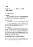
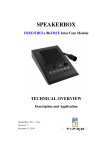
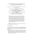
Introduction
1.1
1
OVERVIEW
This book is the second volume of digital signal processing applications
based on the ADSP-2100 DSP microprocessor family. It contains a
compilation of routines for a variety of common digital signal processing
applications. As in the first volume, you may use these routines without
modification or you can use them as a starting point for the development
of routines tailored to your particular needs.
Besides showing the specific applications, these routines demonstrate a
variety of programming techniques for getting the most performance out
of the ADSP-2100 family processors. For example, several routines show
you how to use address pointers efficiently to address circular buffers. We
believe that you will benefit from reading every chapter, even if your
present application uses only a single topic.
Some material in this book was originally published in an applications
handbook that featured modem routines. The information in that volume
was updated and integrated into this book, which supersedes the earlier
publication.
1.2
ADSP-2100 FAMILY PROCESSORS
This section briefly describes the ADSP-2100 family of processors. For
complete information, refer to the ADSP-2100 Family User’s Manual, (ISBN
0-13-006958-2) available from Prentice Hall and Analog Devices. For the
applications in this book, “ADSP-2100” refers to any processor in the
ADSP-2100 family unless otherwise noted. At the time of publication, the
ADSP-2100 Family consisted of the following members:
• ADSP-2100A—DSP microprocessor with off-chip Harvard architecture
• ADSP-2101—DSP microcomputer with on-chip program and data
memory
• ADSP-2103—Low-voltage microcomputer, 3.3-volt version of ADSP2101
1
1
Introduction
• ADSP-2105—Low-cost DSP microcomputer
• ADSP-2111—DSP microcomputer with Host Interface Port
• ADSP-2115—High-performance, Low-cost DSP microcomputer
• ADSP-2161/62/63/64—Custom ROM-programmed DSP
microcomputers
• ADSP-2165/66—Custom ROM-programmed DSP microcomputers
with larger on-chip memories and powerdown
• ADSP-21msp5x—Mixed-Signal DSP microcomputers with integrated,
on-chip analog interface and powerdown
• ADSP-2171—Enhanced ADSP-2100 Family processor offering 33 MIPS
performance, host interface port, powerdown, and instruction set
extensions for bit manipulation, multiplication, biased rounding, and
global interrupt masking
Since Analog Devices strives to provide products that exploit the latest
technology, new family members will be added to this list periodically.
Please contact your local Analog Devices sales office or distributor for a
complete list of available products.
The ADSP-2100A is a programmable single-chip microprocessor optimized
for digital signal processing and other high-speed numeric processing
applications. The ADSP-2100A contains an ALU, a multiplier/
accumulator (MAC), a barrel shifter, two data address generators and a
program sequencer. It features an off-chip Harvard architecture, where
data and program buses are available to external memories and devices.
The ADSP-2101 is a programmable single-chip microcomputer based on the
ADSP-2100A. Like the ADSP-2100A, the ADSP-2101 contains
computational units, as well as a program sequencer and dual address
generators; these elements, combined with internal data and address
busses, comprise the base architecture of the ADSP-2100 Family
microcomputers. Additionally, all family members have the following
core features:
•
•
•
•
2
on-chip data memory, program memory, and boot memory
one or two serial ports
a programmable timer
and enhanced interrupt capabilities.
Introduction 1
To expand the usefulness of the ADSP-2100 Family, the base architecture
has been enhanced with a variety of memory configurations, peripheral
devices, and features for improved performance. Table 1.1 is a matrix that
identifies the functional differences between members of the ADSP-2100
Family.
Model
Instruction Internal
Cycle Time Program
ns
Memory
Internal
Data
Memory
Program
Host
Interface Memory Serial Programmab On-chip
External Low Powe Pin
A/D & D/A Interrupts Modes
Boot
Ports Timer
Port
Coun
ADSP-2100A
80
CACHE
ADSP-210
50
2k x 24
1K X 16
√
2
√
3
1
80/68
ADSP-2102
50
2k x 24
RAM/ROM
1K X 16
√
2
√
3
1
80/68
ADSP-2103(3 V 77
2k x 24
1K X 16
√
2
√
3
1
80/68
ADSP-2105
100
1k x 24
0.5K X 16
√
1
√
3
1
68
ADSP-211
50
2k x 24
1K X 16
√
2
√
3
1
100
ADSP-2115
50
1k x 24
0.5K X 16
√
2
√
3
1
80/68
ADSP-21msp50 77
2k x 24
1K X 16
√
√
2
√
√
3
2
144
ADSP-21msp55 77
2k x 24
1K X 16
√
√
2
√
√
3
2
100
ADSP-21msp56 77
2k x 24 &
2k x 24 ROM
1K X 16
√
√
2
√
√
3
2
100
60
8k x 24 ROM
0.5K X 16
√
2
√
3
1
80/68
ADSP-2162(3 V 100
8k x 24 ROM
0.5K X 16
√
2
√
3
1
80/68
ADSP-2163
60
2k x 24 ROM
0.5K X 16
√
2
√
3
1
80/68
ADSP-2164(3 V 100
2k x 24 ROM
0.5K X 16
√
2
√
3
1
80/68
1K X 24 RAM 4K X 16
12k x 24 ROM
√
2
√
3
1
80
ADSP-2166(3 V 100
2k x 24 ROM
0.5K X 16
√
2
√
3
1
80
30
2k x 24 RAM
8k x 24 ROM
2K X 16
√
2
√
3
1
128
ADSP-216
ADSP-2165
ADSP-217
60
100
4
√
√
Table 1.1 ADSP-2100 Family Functional Differences
3
1 Introduction
This chapter includes overviews of the ADSP-2100 family base
architecture and the three family members that exhibit the most distinct
features. These overviews include the following ADSP-2100 Family
members:
• ADSP-2100 Family Base Architecture–contains the computational units,
address generators, and program sequencer
• ADSP-2101–contains the base architecture, plus on-chip memory
(program, data, and boot memory), a programmable timer, and
enhanced interrupts
• ADSP-2111–contains the features of the ADSP-2101, plus a host
interface port (HIP)
• ADSP-21msp50–contains the features of the ADSP-2101, plus a host
interface port (HIP) and a voice-band analog front end
Other family members are variations on these DSPs. For example, the
ADSP-2105 is based on the ADSP-2101, but it has less on-chip memory
and only one serial port; the ADSP-2171 is similar to the ADSP-2111,
except it has functional enhancements (low-power operation and
expanded instruction set).
Because all the microcomputers of the ADSP-2100 family are codecompatible, the programs in this book can be executed on any DSP in the
family, although some modifications for interrupt vectors, peripherals,
and control registers may be necessary. All the programs in this book,
however, are not designed to use the extra features and functions of some
family members.
1.2.1
ADSP-2100 Family Base Architecture
This section gives a broad overview of the ADSP-2100 family base
architecture (shown in Figure 1.1). Refer to the ADSP-2100 Family User’s
Manual for additional details.
The base architecture contains three full-function and independent
computational units: an arithmetic/logic unit, a multiplier/accumulator
and a barrel shifter. The computational units process 16-bit data directly
and provide for multiprecision computation.
4
Introduction 1
INSTRUCTION
REGISTER
DATA
ADDRESS
GENERATOR
#1
DATA
ADDRESS
GENERATOR
#2
24
PROGRAM
SEQUENCER
14
PMA Bus
14
DMA Bus
PMD Bus
BUS
EXCHANGE
16
DMD Bus
INPUT REGS
INPUT REGS
INPUT REGS
ALU
MAC
SHIFTER
OUTPUT REGS
OUTPUT REGS
OUTPUT REGS
16
Figure 1.1 ADSP-2100 Family Base Architecture
R Bus
A program sequencer and two dedicated data address generators (used to
simultaneously access data in two locations) supply addresses to memory.
The sequencer supports single-cycle conditional branching and executes
program loops with zero overhead. Dual address generators allow the
processor to output simultaneous addresses for dual operand fetches.
Together the sequencer and data address generators allow computational
operations to execute with maximum efficiency. The ADSP-2100 family
uses an enhanced Harvard architecture in which data memory stores data,
and program memory stores instructions and data. This feature lets
ADSP-2100 family processors fetch two operands on the same instruction
cycle.
5
1 Introduction
Five internal buses support the internal components.
•
•
•
•
•
Program Memory Address (PMA) bus
Program Memory Data (PMD) bus
Data Memory Address (DMA) bus
Data Memory Data (DMD) bus
Result (R) bus (which interconnects the computational units)
The program memory data (PMD) bus serves primarily to transfer
instructions from program memory to the instruction register. Instructions
are fetched and loaded into the instruction register during one processor
cycle; they execute during the following cycle while the next instruction is
being fetched. The instruction register introduces a single level of
pipelining in the program flow.
The next instruction address is generated by the program sequencer
depending on the current instruction and internal processor status. This
address is placed on the program memory address (PMA) bus. The
program sequencer uses features such as conditional branching, loop
counters and zero-overhead looping to minimize program flow overhead.
The program memory address (PMA) bus is 14 bits wide, allowing direct
access to up to 16K words of instruction code and data.
The data memory address (DMA) bus is 14 bits wide allowing direct
access of up to 16K words of data. The data memory data (DMD) bus is 16
bits wide. The data memory data (DMD) bus provides a path for the
contents of any register in the processor to be transferred to any other
register, or to any data memory location, in a single cycle. The data memory
address can come from two sources: an absolute value specified in the
instruction code (direct addressing) or the output of a data address
generator (indirect addressing). Only indirect addressing is supported for
data fetches through the program memory bus.
The program memory data (PMD) bus can also be used to transfer data to
and from the computational units through direct paths or through the
PMD-DMD bus exchange unit. The PMD-DMD bus exchange unit permits
data to be passed from one bus to the other. It contains hardware to
overcome the 8-bit width discrepancy between the two buses when
necessary.
Each computational unit contains a set of dedicated input and output
registers. Computational operations generally take their operands from
input registers and load the result into an output register. The
6
Introduction 1
computational units are arranged in parallel rather than cascaded. To
avoid excessive delays when a series of different operations is performed,
the internal result (R) bus allows any of the output registers to be used
directly (without delay) as the input to another computation.
There are two independent data address generators (DAGs). As a pair,
they allow the simultaneous fetch of data stored in program and in data
memory for executing dual-operand instructions in a single cycle. One
data address generator (DAG1) can supply addresses to the data memory
only; the other (DAG2) can supply addresses to either the data memory or
the program memory. Each DAG can handle linear addressing as well as
modulo addressing for circular buffers.
With its multiple bus structure, the ADSP-2100 family architecture
supports a high degree of operational parallelism. In a single cycle, a
family processor can fetch an instruction, compute the next instruction
address, perform one or two data transfers, update one or two data
address pointers and perform a computation. Every instruction can be
executed in a single cycle.
1.2.2
ADSP-2101 Architecture
Figure 1.2 shows the architecture of the ADSP-2101 processor. In addition
to the base architecture, the ADSP-2101 has two serial ports, a
programmable timer, enhance interrupts, and internal program, data and
boot memory.
The ADSP-2101 has 1K words of 16-bit data memory on-chip and 2K
words of 24-bit program memory on-chip. The processor can fetch an
operand from on-chip data memory, an operand from on-chip program
memory and the next instruction from on-chip program memory in a
single cycle.
This scheme is extended off-chip through a single external memory
address bus and data bus that may be used for either program or data
memory access and for booting. Consequently, the processor can access
external memory once in any cycle.
Boot circuitry provides for loading on-chip program memory
automatically after reset. Wait states are generated automatically for
interfacing to a single low-cost EPROM. Multiple programs can be
selected and loaded from the EPROM with no additional hardware.
7
1 Introduction
INSTRUCTION
REGISTER
DATA
ADDRESS
GENERATOR
#1
DATA
ADDRESS
GENERATOR
#2
PROGRAM
MEMORY
DATA
MEMORY
SRAM
SRAM
BOOT
ADDRESS
GENERATOR
PROGRAM
SEQUENCER
24
TIMER
16
14
PMA Bus
PMA Bus
14
DMA Bus
DMA Bus
14
MUX
24
PMD Bus
PMD Bus
24
BUS
EXCHANGE
16
MUX
DMD Bus
EXTERNAL
DATA
BUS
DMD Bus
INPUT REGS
INPUT REGS
ALU
MAC
SHIFTER
OUTPUT REGS
OUTPUT REGS
OUTPUT REGS
INPUT REGS
EXTERNAL
ADDRESS
BUS
COMPANDING
CIRCUITRY
16
R Bus
TRANSMIT REG
TRANSMIT REG
RECEIVE REG
RECEIVE REG
SERIAL
PORT 0
SERIAL
PORT 1
5
5
Figure 1.2 ADSP-2101 Architecture
The memory interface supports memory-mapped peripherals with
programmable wait-state generation. External devices can gain control of
buses with bus request and grant signals (BR and BG). An optional
execution mode allows the ADSP-2101 to continue running from internal
memory while the buses are granted to another master as long as an
external memory operation is not required.
The ADSP-2101 can respond to six user interrupts. There can be up to
three external interrupts, configured as edge- or level-sensitive. Internal
interrupts can be generated from the timer and the serial ports. There is
also a master RESET signal.
The two serial ports (“SPORTs”) provide a synchronous serial interface;
they interface easily and directly to a wide variety of popular serial
devices. They have hardware companding (data compression and
expansion) with both µ-law and A-law available. Each port can generate
an internal programmable clock or accept an external clock.
The SPORTs are synchronous and use framing signals to control data
flow. Each SPORT can generate its serial clock internally or use an external
clock. The framing synchronization signals may be generated internally or
8
Introduction 1
by an external device. Word lengths may vary from three to sixteen bits.
One SPORT (SPORT0) has a multichannel capability that allows the
receiving or transmitting of arbitrary data words from a 24-word or 32word bitstream. The SPORT1 pins have alternate functions and can be
configured as two additional external interrupt pins and Flag Out (FO)
and Flag In (FI).
The programmable interval timer provides periodic interrupt generation.
An 8-bit prescaler register allows the timer to decrement a 16-bit count
register over a range from each cycle to every 256 cycles. An interrupt is
generated when this count register reaches zero. The count register is
automatically reloaded from a 16-bit period register, and the count
resumes immediately.
1.2.3
ADSP-2111 Architecture
Figure 1.3 shows the architecture of the ADSP-2111 processor. The ADSP2111 contains the same architecture of the ADSP-2101—plus a host
interface port (HIP). This section only contains a brief overview; for
detailed descriptions of the HIP and its operation, refer to the ADSP-2111
data sheet and ADSP-2100 Family User’s Manual.
The host interface port is a parallel I/O port that lets the DSP act as a
memory mapped peripheral (slave DSP) to a host computer or processor.
You can think of the host interface port as a collection of dual-ported
memory, or mailbox registers, that let the host processor communicate
with the DSP’s processor core. The host computer addresses the HIP as a
section of 8-bit or 16-bit words of memory. To the processor core, the HIP
is a group of eight data mapped registers.
The host interface port is completely asynchronous. This means that the
host computer can write data into the HIP while the ADSP-2111 is
operating at full speed.
The ADSP-2111 supports two types of booting operations. One method
boots the DSP from external memory (usually an EPROM) through the
boot memory interface. The ADSP-2100 Family User’s Manual describes the
boot memory interface in detail. In the second method, a boot program is
loaded from the host computer through the HIP. Chapter 12, Hardware
Interface includes a sample of code to load a program through the HIP.
9
1
Introduction
INSTRUCTION
REGISTER
DATA
ADDRESS
GENERATOR
#1
DATA
ADDRESS
GENERATOR
#2
PROGRAM
MEMORY
DATA
MEMORY
SRAM
SRAM
BOOT
ADDRESS
GENERATOR
PROGRAM
SEQUENCER
24
TIMER
16
14
PMA Bus
PMA Bus
14
DMA Bus
DMA Bus
EXTERNAL
ADDRESS
BUS
14
MUX
24
PMD Bus
PMD Bus
16
EXTERNAL
DATA
BUS
24
BUS
EXCHANGE
MUX
DMD Bus
DMD Bus
INPUT REGS
INPUT REGS
INPUT REGS
ALU
MAC
SHIFTER
OUTPUT REGS
OUTPUT REGS
OUTPUT REGS
COMPANDING
CIRCUITRY
16
R Bus
HOST
PORT
CONTROL
TRANSMIT REG
TRANSMIT REG
RECEIVE REG
RECEIVE REG
SERIAL
PORT 0
SERIAL
PORT 1
5
EXTERNAL
HOST PORT
BUS
HOST
PORT
DATA
16
5
HOST INTERFACE PORT
Figure 1.3 ADSP-2111 Architecture
1.2.4
11
ADSP-21msp50 Architecture
Figure 1.4 shows the architecture of the ADSP-21msp50 processor The
ADSP-21msp50 contains the same core architecture of the ADSP-2101—
plus a host interface port (described in the previous section) and an analog
interface. This section only contains a brief overview; for detailed
descriptions of the analog interface and its operation, refer to the ADSP21msp50 data sheet and ADSP-2100 Family User’s Manual.
The ADSP-21msp50 has an analog interface that provides the following
features:
•
•
•
•
•
•
•
10
linear-coded 16-bit sigma-delta ADC
linear-coded 16-bit sigma-delta DAC
on-chip anti-aliasing and anti-imaging filters
individual interrupts for the ADC and DAC
8 kHz sampling frequency
programmable gain for DAC and ADC
on-chip voltage reference
Introduction 1
The analog interface is configured and operated through several memory
mapped control and data registers. The ADC and DAC I/O can be
transmitted and received through individual memory mapped registers,
or the data can be autobuffered directly into the processor’s data memory.
3
DATA
ADDRESS
GENERATOR
#1
FLAGS
PROGRAM
SRAM
2K X 24
INSTRUCTION
REGISTER
DATA
SRAM
1K X 16
PROGRAM
ROM
2K X 24
DATA
ADDRESS
GENERATOR
#2
BOOT
ADDRESS
GENERATOR
7
ADC, DAC
AND FILTERS
PROGRAM
SEQUENCER
14
PMA BUS
14
DMA BUS
24
PMD BUS
16
DMD BUS
EXTERNAL
ADDRESS
BUS
14
MUX
EXTERNAL
DATA
BUS
MUX
INPUT REGS
INPUT REGS
INPUT REGS
ALU
MAC
SHIFTER
OUTPUT REGS
OUTPUT REGS
OUTPUT REGS
16
R BUS
COMPANDING
CIRCUITRY
CONTROL
LOGIC
HIP
Control
Transmit Reg
Transmit Reg
Receive Reg
Receive Reg
SERIAL
PORT 0
SERIAL
PORT 1
11
TIMER
HIP
Registers
5
24
HIP Data
BUS
16
5
Figure 1.4 ADSP-21msp50 Architecture
1.3
POWER
DOWN
CONTROL
LOGIC
ASSEMBLY LANGUAGE OVERVIEW
2
The ADSP-2100 family’s assembly language uses an algebraic syntax for
ease of coding and readability. The sources and destinations of
computations and data movements are written explicitly in each assembly
statement, eliminating cryptic assembler mnemonics. Each assembly
statement, however, corresponds to a single 24-bit instruction, executable
in one cycle. Register mnemonics, listed below, are concise and easy to
remember.
11
1 Introduction
Mnemonic
AX0, AX1, AY0, AY1
AR
AF
MX0, MX1, MY0, MY1
MR0, MR1, MR2
MF
SI
SE
SR0, SR1
SB
PX
I0 - I7
M0 - M7
L0 - L7
PC
CNTR
ASTAT
MSTAT
SSTAT
IMASK
ICNTL
RX0, RX1
TX0, TX1
Definition
ALU inputs
ALU result
ALU feedback
Multiplier inputs
Multiplier result (3 parts)
Multiplier feedback
Shifter input
Shifter exponent
Shifter result (2 parts)
Shifter block (for block floating-point format)
PMD-DMD bus exchange
DAG index registers
DAG modify registers
DAG length registers (for circular buffers)
Program counter
Counter for loops
Arithmetic status
Mode status
Stack status
Interrupt mask
Interrupt control modes
Receive data registers (not on ADSP-2100A)
Transmit data registers (not on ADSP-2100A)
Instruction sets for other family members are upward-compatible
supersets of the ADSP-2100A instruction set; thus, programs written for
the ADSP-2100A can be executed on any family member with minimal
changes.
Here are some examples of the ADSP-2100 family assembly language. The
statement
MR = MR + MX1*MY1;
performs a multiply/accumulate operation. It multiplies the input values
in registers MX1 and MY1, adds that product to the current value of the
MR register (the result of the previous multiplication) and then writes the
new result to MR.
12
Introduction 1
The statement
DM(buffer1) = AX0;
writes the value of register AX0 to data memory at the location that is the
value of the variable buffer1.
1.4
DEVELOPMENT SYSTEM
The ADSP-2100 family is supported with a complete set of software and
hardware development tools. The ADSP-2100 Family Development
System consists of Development Software, to aid in software design, and
in-circuit emulators, like the EZ-ICE®, to facilitate the debug cycle.
Development tools, like the EZ-LAB® Development Board, are also
available to provide a hardware platform for experiments and to evaluate
processor functions. Additional development tool capabilities continue to
be added as new members of the processor family are introduced.
The Development Software includes:
• System Builder
This module allows the designer to specify the amount of RAM and ROM
available, the allocation of program and data memory and any memorymapped I/O ports for the target hardware environment. It uses high-level
constructs to simplify this task. This specification is used by the linker,
simulators, and emulators.
• Assembler
This module assembles a user’s source code and data modules. It supports
the high-level syntax of the instruction set. To support modular code
development, the Assembler provides flexible macro processing and
“include” files. It provides a full range of diagnostics.
• Linker
The Linker links separately assembled modules. It maps the linked code
and data output to the target system hardware, as specified by the System
Builder output.
13
1 Introduction
• Simulator
This module performs an instruction-level simulated execution of ADSP2100 family assembly code. The interactive user interface supports full
symbolic assembly and disassembly of simulated instructions. The
Simulator fully simulates the hardware configuration described by the
System Builder module. It flags illegal operations and provides several
displays of the internal operations of the processor.
• PROM Splitter
This module reads the Linker output and generates PROM-programmercompatible files.
• C Compiler
The C Compiler reads ANSI C source and outputs source code ready to be
assembled. It also supports inline assembler code.
In-circuit emulators provide stand-alone, real-time, in-circuit emulation.
The emulators provide program execution with little or no degradation in
processor performance. The emulators duplicate the simulators’
interactive and symbolic user interface.
Complete information on development tools is available from your local
authorized distributor or Analog Devices sales office.
1.5
CONVENTIONS OF NOTATION
The following conventions are used throughout this book:
• Many listings begin with a comment block that summarizes the calling
parameters, the return values, the registers that are altered, and the
computation time of the routine (in terms of the routine’s parameters,
in some cases).
• In listings, all keywords are uppercase; user-defined names (such as
labels, variables, and data buffers) are lowercase. In text, keywords are
uppercase and user-defined names are lowercase italics. Note that this
convention is for readability only.
14
Introduction 1
• In comments, register values are indicated by “=” if the register
contains the value or by “—>” if the register points to the value in
memory.
• All numbers are decimal unless otherwise specified. In listings,
constant values are specified in binary, octal, decimal, or hexadecimal
by the prefixes B#, O#, D#, and H#, respectively.
1.6
PROGRAMS ON DISK
1.7
FOR FURTHER SUPPORT
This book includes an IBM PC 31⁄2 inch high-density diskette containing
the routines that appear in this book. As with the printed routines, we
cannot guarantee suitability for your application.
If you need applications engineering assistance with the applications in
this book, please contact:
Applications Engineering from your local Analog Devices distributor
Analog Devices, Inc.
DSP Applications Engineering
One Technology Way
Norwood, MA 02062-9106
Tel: (617) 461-3672
Fax: (617) 461-3010
e_mail: [email protected]
Or log into the DSP Bulletin Board System:
Tel: (617) 461-4258
300, 1200, 2400, 9600, 14400 baud, no parity, 8 bits data, 1 stop bit
15