1
eZ80F91 Development Kit
User Manual
24
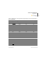
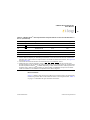
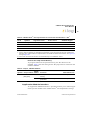
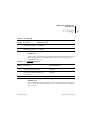
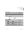
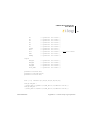
Table 10. GPIO Data Register
Function/Bit #
7
6
5
4
3
2
1
GPIO D0
X
GPIO D1
X
GPIO D2
X
GPIO D3
X
GPIO D4
X
GPIO D5
X
GPIO D6
GPIO D7
0
X
X
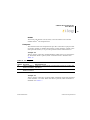
Modem Reset
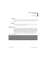
The Modem Reset signal, MRESET, is used to reset an optional socket
modem. This signal is controlled by bit 5 in the register shown in Table 15.
The MRESET signal is available at the embedded modem socket interface (J9, Pin 1). Setting this bit Low places the optional socket modem into
a reset state. You must pull this bit High again to enable the socket modem.
Reference the appropriate documentation for the socket modem to reset
timing requirements.
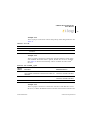
User Triggers
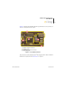
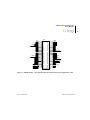
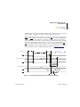
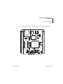
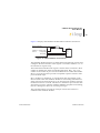
Two trigger output pins are provided on the eZ80Acclaim!® Development
Kit. Labeled J21 (Trig2) and J22 (Trig1), these pins allow you to trigger
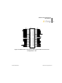
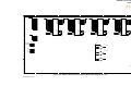
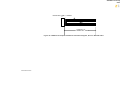
external equipment to aid in the debug of the system. See Figure 8 for
trigger pin details.
UM014220-0508
eZ80 Development Kit