1
GE
Measurement & Control
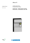
Druck ADTS 505 Air Data Test Set
User Manual K0260
© 2013 General Electric Company. All Rights Reserved. Specifications are subject to change without notice. GE is a
registered trademark of General Electric Company. Other company or product names mentioned in this document may
be trademarks or registered trademarks of their respective companies, which are not affiliated with GE.
i
Introduction
This technical manual provides operating instructions for the Air Data Test System compatible
with the requirements of first line operation for the technician and supervisor.
Scope
This technical manual contains a brief description, operation and testing procedures for the
user of this equipment with software version V1.08.
Safety
The manufacturer has designed this equipment to be safe when operated using the
procedures detailed in this manual. Do not use this equipment for any other purpose than that
stated, the protection provided by the equipment may be impaired.
This publication contains operating and safety instructions that must be followed to make sure
of safe operation and to maintain the equipment in a safe condition. The safety instructions are
either warnings or cautions issued to protect the user and the equipment from injury or
damage.
Use qualified* technicians and good engineering practice for all procedures in this publication.
PIN Protection
The ADTS 505 contains two protected menus, the operating limits (described in this manual)
and the maintain calibration menu (described in the calibration manual).
The factory set PIN codes are contained in an envelope addressed to the Supervisor.
IMPORTANT NOTE
Change these codes for authorised access. Unauthorised access to these two menus can make
this system inaccurate and could, in control mode, cause excessive rates of pressure change.
Pressure
Do not apply pressure greater than the maximum safe working pressure to the equipment.
Toxic Materials
There are no known toxic materials used in this equipment.
Maintenance
The equipment must be maintained using the manufacturer’s procedures and should be
carried out by authorized service agents or the manufacturer’s service departments
Technical Advice
For technical advice contact the manufacturer or subsidiary.
*
A qualified technician must have the necessary technical knowledge, documentation, special test
equipment and tools to carry out the required work on this equipment.
K0260 Issue No. 8
ii
Druck ADTS 505 User Manual
Associated Publications
This lists the manuals and publications referenced in this manual.
Calibration Manual
Air Data Test Set ADTS 505
K272
Quick Reference Guide
Air Data Test Set ADTS 505
K274
Approved Service Agents
Internet www.ge-mcs.com
Markings and Symbols
This equipment meets the requirements of all relevant European safety directives. The
equipment carries the CE mark.
This symbol, on the instrument, indicates that the user should refer to the user manual. This
symbol, in this manual, indicates a hazardous operation.
Do not dispose of this product as household waste. Use an approved organisation that
collects and/or recycles waste electrical and electronic equipment. For more information,
contact one of these:
•
our customer service department (contact us at www.ge-mcs.com)
•
your local government office
Approved Service Agents
For a list of approved service agents, visit our website: www.ge-mcs.com
K0260 Issue No. 8
CONTENTS
iii
Table of Contents
Preliminary pages
Introduction .................................................................................................................................................................................. ............... i
Scope
.................................................................................................................................................................................. ............... i
Associated Publication................................................................................................................................................................... ............... ii
Approved Service Agents.............................................................................................................................................................. ............... ii
Table of contents (this table)....................................................................................................................................................... ............... iii
Abbreviations .................................................................................................................................................................................. ............... vii
Glossary
.................................................................................................................................................................................. ............... ix
Pressure units and conversion factors................................................................................................................................. ............... xi
Section
1
Title
1.1
1.2
2
Introduction......................................................................................................................................................... ............... 1-1
Operating Limits............................................................................................................................................... ............... 1-3
INSTALLATION
2.1
2.2
2.3
2.4
2.5
2.6
3
page
DESCRIPTION
Packaging........................................................................................................................................................... ............... 2-1
Packaging for Storage and Transportation....................................................................................... ............... 2-1
Return Goods Procedure............................................................................................................................. ............... 2-3
Electrical Connection..................................................................................................................................... ............... 2-6
Pneumatic Pressure Connection............................................................................................................. ............... 2-7
Positioning of the ADTS 505....................................................................................................................... ............... 2-8
OPERATION
3.1
3.2
3.3
3.4
3.5
3.6
3.7
Preparation.......................................................................................................................................................... ............... 3-1
Display Functions and Units of Measure............................................................................................. ............... 3-2
Quick Reference............................................................................................................................................... ............... 3-3
First Time Operators....................................................................................................................................... ............... 3-4
3.4.1..... Operating Modes............................................................................................................................ ............... 3-6
Operation and Example Procedures..................................................................................................... ............... 3-10
3.5.1..... Operating Procedures.................................................................................................................. ............... 3-10
3.5.2..... Power-up............................................................................................................................................. ............... 3-10
3.5.3..... Control or Measure Parameter................................................................................................ ............... 3-11
3.5.4..... Leak Testing the ADTS 505......................................................................................................... ............... 3-11
3.5.5..... Changing the Units of Measurement.................................................................................... ............... 3-13
3.5.6..... Setting Limits..................................................................................................................................... ............... 3-13
Tests Before Use.............................................................................................................................................. ............... 3-15
3.6.1..... Aircraft System Protection......................................................................................................... ............... 3-15
Testing Aircraft Systems or UUT.............................................................................................................. ............... 3-15
3.7.1..... Testing the Aircraft Static System........................................................................................... ............... 3-16
3.7.2..... Testing the Aircraft Pitot System............................................................................................. ............... 3-17
3.7.3..... Combined Testing of the Aircraft Pitot and Static Systems........................................ ............... 3-18
3.7.4..... Mach Test and Constant Mach................................................................................................ ............... 3-19
3.7.5..... Leak Testing....................................................................................................................................... ............... 3-20
3.7.6..... Airspeed Switch Test..................................................................................................................... ............... 3-21
3.7.7..... Engine Pressure Ratio (EPR)....................................................................................................... ............... 3-22
3.7.8..... Go To Ground.................................................................................................................................... ............... 3-23
K0260 Issue No. 8
iv
Druck ADTS 505 User Manual
Table of Contents (contd)
Section
Title
3.8
3.9
3.10
4
MAINTENANCE
4.1
4.2
4.3
4.4
5
Introduction......................................................................................................................................................... ............... 4-1
Materials and Tools......................................................................................................................................... ............... 4-2
Maintenance Tasks......................................................................................................................................... ............... 4-3
Routine Maintenance..................................................................................................................................... ............... 4-4
TESTING AND FAULT FINDING
5.1
5.2
5.3
5.4
5.5
5.6
6
page
Manual Venting of the Aircraft Pitot and Static Systems............................................................. ............... 3-24
ADTS 505 Options............................................................................................................................................ ............... 3-24
Set-up Reference............................................................................................................................................. ............... 3-25
Introduction......................................................................................................................................................... ............... 5-1
Standard Serviceability Test...................................................................................................................... ............... 5-2
Fault Diagnosis................................................................................................................................................. ............... 5-3
Warnings and Self-test Errors.................................................................................................................. ............... 5-3
Further Testing.................................................................................................................................................. ............... 5-6
Fault Finding....................................................................................................................................................... ............... 5-14
REFERENCE and SPECIFICATION
6.1
6.2
6.3
Introduction......................................................................................................................................................... ............... 6-1
Key-pad Selections and Functions......................................................................................................... ............... 6-1
F1 - F6................................................................................................................................................................... ............... 6-1
ALT/Ps................................................................................................................................................................... ............... 6-2
SPEED Qc.............................................................................................................................................................. ............... 6-2
MACH..................................................................................................................................................................... ............... 6-3
ROC Ps RATE........................................................................................................................................................ ............... 6-3
RATE ....................................................................................................................................................................... ............... 6-4
LEAK MEASURE/CONTROL.......................................................................................................................... ............... 6-5
GROUND................................................................................................................................................................ ............... 6-5
0 to 9...................................................................................................................................................................... ............... 6-6
-000........................................................................................................................................................................ ............... 6-6
CLEAR/QUIT......................................................................................................................................................... ............... 6-6
DELETE................................................................................................................................................................... ............... 6-6
HELP....................................................................................................................................................................... ............... 6-7
ENTER ................................................................................................................................................................... ............... 6-7
CLEAR/QUIT + ENTER (ABORT)................................................................................................................... ............... 6-7
Main Menu........................................................................................................................................................... ............... 6-8
[Rate Timer]......................................................................................................................................................... ............... 6-8
[Units] ................................................................................................................................................................... ............... 6-9
[EPR]....................................................................................................................................................................... ............... 6-10
[Hold] ..................................................................................................................................................................... ............... 6-10
Nudge [ or .].............................................................................................................................................. ............... 6-10
SETUP ................................................................................................................................................................... ............... 6-11
6.3.1..... Set-up 1 of 2....................................................................................................................................... ............... 6-11
............... [Display],[Single, Dual, Quad, Hand Term]........................................................................... ............... 6-11
K0260 Issue No. 8
CONTENTS
v
Table of Contents (contd)
Section
Title
6.4
6.5
page
[Units] ................................................................................................................................................................... ............... 6-12
[Limits]................................................................................................................................................................... ............... 6-13
[Alt. Corr.].............................................................................................................................................................. ............... 6-15
[Date Format]..................................................................................................................................................... ............... 6-16
6.3.2..... Set-up 2 of 2....................................................................................................................................... ............... 6-17
............... [Operational Hours]....................................................................................................................... ............... 6-17
............... [Software Versions]........................................................................................................................ ............... 6-17
............... [Security].............................................................................................................................................. ............... 6-17
............... [Maintain Calibration]................................................................................................................... ............... 6-17
............... [Auto Leak].......................................................................................................................................... ............... 6-18
Other Features.................................................................................................................................................. ............... 6-19
Elapsed Time Counter.................................................................................................................................... ............... 6-19
............... Auto Zero............................................................................................................................................. ............... 6-19
............... Hand Terminal Option A.............................................................................................................. ............... 6-19
............... Hand Terminal Option B.............................................................................................................. ............... 6-19
............... ............... Template Format for Creating Test Sequence Files....................................... ............... 6-32
............... ............... Option B Advanced Hand Terminal Specification........................................... ............... 6-41
Specification........................................................................................................................................................ ............... 6-42
K0260 Issue No. 8
vi
Druck ADTS 505 User Manual
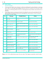
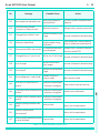
Table of Illustrations
Figure
Title
page
1-1
2-1
2-2
2-3
2-4
3-1
4-1
5-1
5-2
5-3
5-4
6-1
6-2
6-3
6-4
6-5
6-6
6-7
6-8
6-9
6-10
6-11
6-12
6-13
ADTS 505 General View............................................................................................................................... ............... 1-2
ADTS 505 Accessories................................................................................................................................... ............... 2-4
ADTS 505 Altitude Correction On-aircraft........................................................................................... ............... 2-9
ADTS 505 Altitude Correction Off-aircraft........................................................................................... ............... 2-9
ADTS 505 General View............................................................................................................................... ............... 2-10
Key-pad and Display...................................................................................................................................... ............... 3-3
Fuse Replacement........................................................................................................................................... ............... 4-5
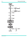
Fault Finding Chart......................................................................................................................................... ............... 5-4
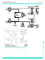
System Screen for Diagnosis.................................................................................................................... ............... 5-7
System Screen.................................................................................................................................................. ............... 5-9
Key-pad Test Display..................................................................................................................................... ............... 5-10
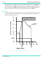
ARINC 565 Limits Graph.............................................................................................................................. ............... 6-14
Altitude Correction On-aircraft................................................................................................................ ............... 6-15
Altitude Correction Off-aircraft................................................................................................................ ............... 6-16
Interconnection................................................................................................................................................ ............... 6-20
Power-up Displays.......................................................................................................................................... ............... 6-21
Main Menu Screen.......................................................................................................................................... ............... 6-22
Main Menu Structure..................................................................................................................................... ............... 6-23
Manual Control Selections......................................................................................................................... ............... 6-24
Set-up Menu Selections............................................................................................................................... ............... 6-27
Test Sequence Selections........................................................................................................................... ............... 6-30
Customer Test Sequence File Selections............................................................................................. ............... 6-31
System Status..................................................................................................................................................... ............... 6-38
Example Error Screen.................................................................................................................................... ............... 6-39
Table
Title
2-1
4-1
4-2
4-3
5-1
5-2
5-3
5-4
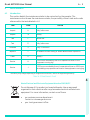
Parts List............................................................................................................................................................... ............... 2-5
Maintenance Chart......................................................................................................................................... ............... 4-1
Materials List....................................................................................................................................................... ............... 4-2
Tool and Test Equipment Requirements.............................................................................................. ............... 4-2
Fault Finding...................................................................................................................................................... ............... 5-5
System Screen Information....................................................................................................................... ............... 5-8
Error Messages................................................................................................................................................. ............... 5-14
Warning Messages......................................................................................................................................... ............... 5-15
List of Tables
page
K0260 Issue No. 8
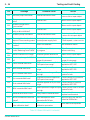
Abbreviations
vii
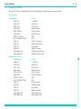
Abbreviations
The following abbreviations are used in this manual; the abbreviations are the same in the singular and plural.
A
Ampere
abs
Absolute
a.c.
Alternating current
ADTS
Air Data Test Set
ALT
Altitude
ARINC
Air Radio Incorporated
ASI
Airspeed indicator
CAS
Calibrated airspeed
COSHH
Control of Substances Hazardous to Health Regulations
cm
Centimetre
d.c.
Direct current
Def
Define
e.g.
For example
EPR
Engine pressure ratio
etc.
And so on
°F
Degrees Fahrenheit
Fig.
Figure
ft
Foot
g
Gauge
h
Hour
HBC
High breaking capacity
Hg
Mercury
hm
Hecto metre
Hz
Hertz
IAS
Indicated airspeed
i.e.
That is
in
Inch
kg
Kilogram
km
Kilometre
kts
Knots
LCD
Liquid crystal display
m
Metre
mA
Milliampere
max
Maximum
mbar
Millibar
min
Minute or minimum
mm
Millimetre
mph
Miles per hour
MSDS
Material safety data sheet
mV
Millivolts
No.
Number
PIN
Personal identification number
Ps
Static pressure
psi
Pounds per square inch
Pt
Total pressure (Pitot)
Qc
Differential pressure Ps-Pt
QFE
Local atmospheric pressure
QNH
Barometric pressure at sea level
K0260 Issue No. 8
Druck ADTS 505 User Manual
viii
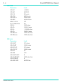
Abbreviations (contd)
RGA
RH
RMS
ROC
Rt
SST
V
+ve
-ve
°C
°F
Return Goods Authorization (Druck procedure)
Relative humidity
Root mean square
Rate of climb
Rate
Standard serviceability test
Volts
Positive
Negative
Degrees Celsius
Degrees Fahrenheit
K0260 Issue No. 8
Glossary
ix
Glossary
Terminology
The terminology used in this manual is specific and individual interpretation must not be
introduced. The terms are defined as follows:
Adjust
To bring to a more satisfactory state; to manipulate controls, levers, linkages, etc. to return equipment
from an out-of-tolerance condition to an in-tolerance condition.
Align
To bring into line; to line up; to bring into precise adjustment, correct relative position or coincidence.
Assemble:To fit and secure together the several parts of; to make or form by combining parts.
Calibrate: To determine accuracy, deviation or variation by special measurement or by comparison with a
standard.
Check:
Make a comparison of a measure of time, pressure, temperature, resistance, dimension or other
quality with a known figure for that measurement.
Disconnect:To detach the connection between; to separate keyed or matched equipment parts.
Dismantle:To take apart to the level of the next smaller unit or down to all removable parts.
Examine: To perform a critical visual observation or check for specific conditions; to test the condition of.
Fit:
Correctly attach one item to another.
Inspect: Review the work carried out by Specialists to ensure it has been performed satisfactorily.
Install:
To perform operations necessary to properly fit an equipment unit into the next larger assembly or
system.
Maintain: To hold or keep in any particular state or condition especially in a state of efficiency or validity.
Operate: Make sure that an item or system functions correctly as far as possible without the use of test
equipment or reference to measurement.
Readjust: To adjust again; to move back to a specified condition; to bring back to an in-tolerance condition.
Reconnect:To rejoin or refasten that which has been separated.
Refit:
Fit an item which has previously been removed.
K0260 Issue No. 8
x
Druck ADTS 505 User Manual
Remove: To perform operations necessary to take an equipment unit out of the next larger assembly or
system. To take off or eliminate. To take or move away.
Repair:
To restore damaged, worn out or malfunctioning equipment to a serviceable, usable or operable
condition.
Replace: Remove an item and fit a new or a serviced item.
Reset:
To put back into a desired position, adjustment or condition.
Service:
To perform such operations as cleaning, lubricating and replenishing to prepare for use.
Test:
Ascertain by using the appropriate test equipment that a component or system functions correctly.
K0260 Issue No. 8
xi
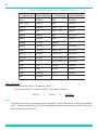
Table of pressure units and conversion factors
Pressure unit
Factor (Pascals)
Pressure unit
Factor (Pascals)
bar
100000
lbf/ft2
47.8803
lbf/in2 (psi)
6894.76
inHg
3386.39
mH2O
9806.65
inH2O
[1]
249.089
mbar
100
ftH2O
[1]
2989.07
kgf/cm2
98066.5
atm
101325.0
kgf/m2
9.80665
pdl/ft2
1.48816
mmHg
133.322
dyn/cm2
0.1
cmHg
1333.22
hbar
10000000
mHg
133322.0
tonf/ft2 (UK)
107252.0
mm/H2O
[1]
9.80665
tonf/in2 (UK)
15444300
cm/H2O
[1]
98.0665
inH2O (USA) [2]
248.64135
N/m2
1
ftH2O (USA) [2]
2983.6983
hPa
100
kP/mm2
9806650
kP a
1000
kP/cm2
98066.5
MPa
1000000
torr
133.322
2
kP/m
9.80665
Unit Conversion
To convert FROM pressure VALUE 1 in pressure UNITS 1
TO pressure VALUE 2 in pressure UNITS 2, calculate as follows:
VALUE 2
=
VALUE 1
x
FACTOR 1
FACTOR 2
Note:
The conversion factor for pressure units referenced [1] are calculated for a water temperature
of 4°C. Pressure units referenced [2] are calculated for a water temperature of 68°F these units
are normally used in the USA.
K0260 Issue No. 8
Druck ADTS 505 User Manual
xii
K0260 Issue No. 8
Description
1- 1
1
INTRODUCTION
1.1
Introduction
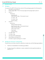
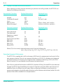
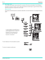
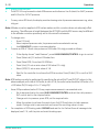
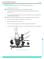
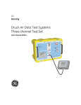
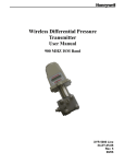
The ADTS 505 is a self-contained flight-line air data test system, enclosed in an ABS case. The
unit provides complete pressure and vacuum measuring and control for on-aircraft sense and
leak testing, functional tests of air data instruments, components and systems.
The ADTS 505 displays and operates in either units of pressure measurement or aeronautical
units. In the control mode, the rate that the pressures change towards new set-points can be
controlled in true aeronautical rate units.
There are two independent pneumatic channels connect to the aircraft or instrument systems,
one for static and one for pitot. They can be operated as measure only channels with leak
testing facilities or each can be control channels producing true pressure conditions for altitude
and airspeed. Two pneumatic outlet ports, on the front panel and identified as Ps (static) and
Pt (pitot) provide connection to the aircraft system or unit under test.
To protect sensitive instruments and equipment a `ground' facility automatically and safely
controls both channels to atmospheric pressure at the previously entered rates of change and
then informs the user when both channels are safely at `ground'.
Pre-defined sets of limits, stored in the system, prevent excessive pressures and rates
damaging aircraft systems and components. A further five sets of operating limits can be
defined by the supervisor or quality assurance engineer. The user can select sets of limits but
cannot change the values.
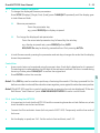
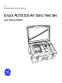
The user interface is either the key-pad and display on the front panel or one of two types of
optional hand terminal connected to the front panel. The two types of hand terminal are
identified as option A and option B.
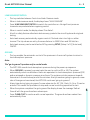
The option A hand terminal contains all the facilities of the front panel key-pad and display.
The key-pad contains fixed function keys used to select various parameters, modes and enter
numeric values. The display shows various menus, each menu provides selections using six
menu-defined function keys.
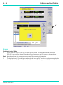
The option B advanced hand terminal is a computer-based device that contains all the facilities
of option A on a touch-sensitive, Windows® display, colour screen. It also up-loads and downloads user-defined test programs and displays the resulting test data.
The integral pumps of the ADTS 505, produce pressure and vacuum supplies for the unit's
controlling requirements. The power supply connection for the unit is located on the front panel.
K0260 Issue No. 8
1
1-2
Druck ADTS 505 User Manual
Air Data Test
Mach
Set - Hand Termin
Leak Measure
0.001
al
Mach
E MODE
LEAK MEASUR
T5.0A
250V
HBC
Option A Hand Terminal
DO
TH NO
ES T O
E B
W V ST
D AT EN R
RE T U
AR S C
IN
T
g
Advanced Hand Terminal
Option B Hand Terminal
FIGURE 1-1 ADTS 505 GENERAL VIEW
K0260 Issue No. 8
Description
1.2
1- 3
Operating Limits
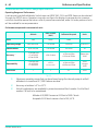
The ADTS 505 is supplied with the following pre-defined operating limits.
Civil Limits
Parameter
Limit
MIN ALT
MAX ALT
MIN CAS
MAX CAS
MAX MACH
MAX ROC
ARINC LIMITS
ALT CORRECTION
MIN Ps
MAX Ps
MIN Qc
MAX Qc
MAX Rate Ps
MAX Rate Qc
Standard Limits
-1,000 ft
50,000 ft
0.0 knots
450.0 knots
1.000 Mach
6,000 ft/min
OFF
0 ft
115.972 mbar
1050.406 mbar
0.0 mbar
368.01 mbar
109.85 mbar/min
109.85 mbar/min
Parameter
Limit
MIN ALT
MAX ALT
MIN CAS
MAX CAS
MAX MACH
MAX ROC
ARINC LIMITS
ALT CORRECTION
MIN Ps
MAX Ps
MIN Qc
MAX Qc
MAX Rate Ps
MAX Rate Qc
-2,000 ft
60,000 ft
0.0 knots
650.0 knots
1.732 Mach
10,000 ft/min
OFF
0 ft
65.00 mbar
1088.6 mbar
0.0 mbar
866.00 mbar
200 mbar/min
200 mbar/min
1
K0260 Issue No. 8
1-4
Druck ADTS 505 User Manual
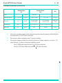
Max Limits
Parameter
Limit
MIN ALT
MAX ALT
MIN CAS
MAX CAS
MAX MACH
MAX ROC
ARINC LIMITS
ALT CORRECTION
MIN Ps
MAX Ps
MIN Qc
MAX Qc
MAX Rate Ps
MAX Rate Qc
-2,000 ft
60,000 ft
0.0 knots
650.0 knots
2.800 Mach
40,000 ft/min
OFF
0 ft
10.90 mbar
1355.00 mbar
-1355.00 mbar
2490.00 mbar
1000 mbar/min
1000 mbar/min
EPR Limits
Parameter
Limit
MIN INLET
MAX INLET
MIN OUTLET
MAX OUTLET
MIN EPR
MAX EPR
MIN INLET RATE
MAX INLET RATE
MIN EPR RATE
MAX EPR RATE
27.0 mbar
1355.0 mbar
27.0 mbar
2500.0 mbar
0.1
10.0
0
1000 mbar/min
0
60 EPR/min
K0260 Issue No. 8
Druck ADTS 505 User Manual
2
INSTALLATION
2.1
Packaging
2- 1
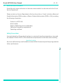
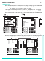
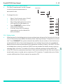
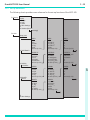
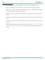
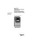
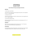
On receipt of the ADTS 505 check the contents of the packaging against the following lists:
i)
ADTS 505 Air Data Test Set
ii)
Power supply cable - 5 m, no line plug (regional line plugs require option C)
iii)
Option A
comprising:
Hand terminal
Hand terminal cable - 18 m (option A only)
5 m hose - red
5 m hose - blue
Accessory Bag
iv)
Option B
comprising:
Advanced hand terminal
Hand terminal cable - 18 m (option B only)
Cable, communications
Cable, power supply
Power pack
Accessory Bag
v)
3 m hose - red
vi)
3 m hose - blue
vii)
User Manual (this publication)
viii)
Quick Reference Guide K0274
ix)
Kit, fuse/o-ring (also see Figure 2-1, item1)
2.2
Packaging for Storage or Transportation
To store the unit or to return the unit for calibration or repair carry out the following procedures:
1.
Pack the unit as detailed in the following procedure.
2.
To return the unit for calibration or repair complete the return goods procedure as
detailed in 2.3.
K0260 Issue No. 8
2
2-2
Installation
Procedure
The unit should be at zero/ambient pressure. Disconnect the hose assemblies and stow in the
lid.
•
Switch OFF and disconnect from the electrical power supply. Disconnect the power
supply cable and the hand terminal cable. Disconnect the hand terminal cable from the
hand terminal.
•
Fit the lid to the unit.
•
The power supply cable, hand terminal cable and the hand terminal should be placed
in the original packing material.
If available, use the original packing material. When using packing materials other than the
original, proceed as follows.
•
Wrap unit in polyethylene sheeting.
•
Select a double-wall cardboard container. Inside dimensions must be at least 15 cm
greater than the equipment. The carton must meet test strength requirements of >125 kg.
•
Protect all sides with shock-absorbing material to prevent equipment movement within
the container.
Seal carton with approved sealing tape.
Mark carton “FRAGILE” on all sides, top, and bottom of shipping container.
To return the unit for calibration or repair complete the return goods procedure as detailed in 2.3.
Environment
The following conditions apply for both shipping and storage:
•
Temperature Range........... ............-20 to +70°C (-4 to +158°F)
•
Altitude......... ............Up to 15,000 feet (4,570 metres)
K0260 Issue No. 8
Druck ADTS 505 User Manual
2.3
2- 3
Returned Goods Procedure
Should the unit require calibration or become unserviceable it can be returned to the Druck
Service Department.
Please contact our Service Department, either by 'phone, fax or E-mail, to obtain a Returned
Goods Authorization (RGA) number or (Return Material Authorization [RMA] in USA), providing
the following information:
Product (i.e. ADTS 505)
Serial number
Details of defect/work to be undertaken
Calibration traceability requirements
Operating conditions
Safety Precautions
You must also tell us if the product has been in contact with anything hazardous or toxic and,
the relevant COSHH (MSDS in USA) references and precautions to be taken when handling.
IMPORTANT NOTICE
Service or calibration by unauthorized sources will affect the warranty and may not guarantee
further performance
2
K0260 Issue No. 8
2-4
Installation
4
1
Air Data Test
al
Set - Hand Termin
Leak Measure
0.001
RE MODE
Mach
5
Mach
LEAK MEASU
18m
2
3A
6
9
11
g
Advanced Hand Terminal
13
12
191-19
10
18m
8
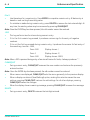
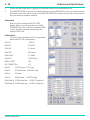
Note:
Item 13 supplied for the country of use
FIGURE 2-1 ADTS 505 ACCESSORIES
K0260 Issue No. 8
Druck ADTS 505 User Manual
No
1
2
2- 5
Part Number
AS505-18-3124M0
AS505-53-3124M0
Qty per
assy
Description
Kit, fuse/o-ring comprising:
o-ring AN4
fuse, T5.0A/250V HBC
comprising:
Hose, red, ST/OPN, AN4, 3m
1
1
Hose, blue, ST/OPN, AN4, 3m
1
3A
AS505-40-3124M0
Cable, AC Power, 5M (open end)
1
3B#
AS505-40-3124M0
† Cable, AC Power, 5M (250V UK plug)
1
3C#
AS505-41-3124M0
† AC Power, 5M (115V US plug)
1
3D#
AS505-42-3124M0
† AC Power, 5M (250V European plug)
1
4
AS505-56-3124M0
4.1#
-
Option A
Hand terminal Assembly
Option A and B
Hose, red, 5M
Hose, blue, 5M
Option A
Cable, Hand terminal 18M (option)
1
1
5
AS505-54-3124M0
6
AS505-57-3124M0
Option A and B
Bag, Accessory, Hand Terminal
1
7#
AS505-60-3124M0
Handbook, User Manual, K0260
1
8#
AS505-61-3124M0
Handbook, Calibration Manual, K0272
1
9
AS505-56-3124M1
Option B
Hand terminal, Advanced
1
10
AS505-54-3124M1
Option B
Cable, Hand terminal 18M, Safety marking (option)
1
11
AS204-06-3435M0
Cable, Communications PC
1
12
AS204-07-3435M0
Power pack
1
13
-
part of item 12 -Adaptor, power pack (comprising: 4)
1
14
AS204-10-3435M0
Stylus, pack (comprising: 3)
1
1
# not illustrated † alternative
TABLE 2-1 PARTS LIST
K0260 Issue No. 8
2
2-6
2.4
Installation
Electrical Connection
WARNING: VOLTAGES IN EXCESS OF 30 VOLTS (RMS) AC OR 50 VOLTS DC, IN CERTAIN
CIRCUMSTANCES, CAN BE LETHAL. CARE MUST BE TAKEN WHEN WORKING ON LIVE,
EXPOSED CONDUCTORS.
Power Supply Connection
The unit must be connected to the correct electrical power supply as stated, adjacent to the
power connector.
Open end cables
Only a qualified technician (see page i) must fit a connector to a cable supplied by GE (see Table 2-1,
item 3).
CAUTIONS:
1
THE SUPPLY MUST PROVIDE CONNECTION TO A PROTECTIVE GROUND TERMINAL. THE UNIT MUST, AT
ALL TIMES, BE CONNECTED TO THE SUPPLY EARTH (GROUND).
2
THE POWER SUPPLY CABLE AND CONNECTOR MUST BE CORRECTLY RATED FOR THE POWER SUPPLY.
Note: The ADTS 505 is normally supplied with an approved power supply cable for use in the country
of delivery. This can limit the maximum supply voltage that can be safely used.
e.g. a NEMA 5-15P terminated cable, for use in the U.S.A., is approved for a maximum of 125 V
ac; it must be replaced for a higher supply voltage.
Pin
(ADTS)
1
4
Centre
European
Colour
Brown
Blue
Green/Yellow
U.S.
Color
Black
White
Green
Function
Live
Neutral
Protective Earth (Ground)
Make sure that the power supply is off before connecting the power cable.
If required, connect the hand terminal to the connector on the front panel.
Note: Connecting the hand terminal to the unit disables the front panel key-pad.
Fuses
The two fuses, located in the holders and mounted on the front panel, protect the unit. The
fuses are connected in the live and neutral supply circuit and are T5.0A/250V HBC type.
Note: Only replace the fuses with the correct type, see Figure 2-1 item1, to replace see section 4-5.
External earth/ground connection
An external earth (ground) cable may be connected to the stud on the front panel of the unit
providing integrity of the earth (ground) connection.
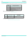
100 / 120 / 230V ~ 50 / 60Hz 200VA
115V ~ 400Hz 200VA
FIGURE 2-2 POWER SUPPLY LABEL
K0260 Issue No. 8
Druck ADTS 505 User Manual
2- 7
Connection
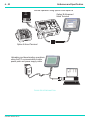
•
The ADTS 505 provides a power supply to the advanced hand terminal when connected to the
hand terminal connector on the front panel.
•
The power supplies must be isolated when connecting the advanced hand terminal in the
hazardous area.
Using the advanced hand terminal when not connected to the ADTS 505
Using the advanced hand terminal with a pc to create test scripts.
•
•
The unit must be connected to the correct electrical power supply, see paragraph 2.4.
Before use, make sure the SELV power adaptor supplied with the instrument is correct for the
power supply voltage. The Safety Extra Low Voltage (SELV) power adaptor complies with
EN61010 (including safety requirements for laboratory instruments).
Note: The instrument can be powered from other DC power supplies of the correct voltage range. It
is the user’s responsibility to make sure the power supply is safe.
Make sure that the power supply is off before connecting the power cable.
Communications Connection
Communications cable - parts list item 11
Pin No.
ADTS
2.5
Function
Connector
Cable
Colour
1
0V
Jack plug outer
BLK
2
+ VIN
Jack plug inner
BLK-W
3
RS232 Tx
PIN 2
RED
4
RS232 Rx
PIN 3
GRN
5
RS232 0V
PIN 5
BLK
Pneumatic Pressure Connections
Ps (static)- AN4 (MS33656-4)
Pt (pitot)- AN4 (MS33656-4)
When not in use, a blanking cap must be fitted.
Note: When carrying out a leak test, a leak of this blanking cap affects the performance of the ADTS 505.
K0260 Issue No. 8
2
2-8
2.6
Installation
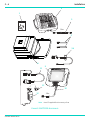
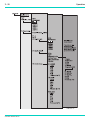
Positioning of the ADTS 505
WARNING: IN AN ENCLOSED AREA WITH FUEL VAPOUR PRESENT THIS EQUIPMENT MUST BE
PLACED AT LEAST 0.5 METRES ABOVE FLOOR LEVEL. THIS EQUIPMENT CONTAINS A
D.C. MOTOR WITH BRUSHES THAT COULD CAUSE A SPARK.
CAUTION:
TO OPERATE, PLACE THE UNIT ON A HORIZONTAL SURFACE (FRONT PANEL UPPERMOST) OR VERTICALLY
(POWER SUPPLY CONNECTOR UPPERMOST) THIS ALLOWS THE WATER IN THE WATER FILTER TO VENT.
WATER COULD CONTAMINATE THE CONTROLLER MANIFOLD AND AFFECT CONTROLLER PERFORMANCE.
Note: In control mode, the water drain, located at one end of the unit near the carrying handle, produces
a flow of air and some water. The amount of water depends on the humidity and the operating
time in control mode.
CAUTION:
BEFORE USE, CHECK THE WATER DRAIN PIPE, IT MUST BE FREE OF OBSTRUCTION. WHEN IN CONTROL
MODE CHECK THAT A SMALL FLOW OF AIR COMES OUT OF THE DRAIN PIPE.
Notes:
1
When checking for a small flow of air do not block the drain pipe completely this causes a backpressure in the pipe and controller instability.
2
If no air flows from the drain pipe, when in control mode, switch off and start again. If no air
flows after a re-start, switch off and do not use the ADTS 505, return the unit to the repair depot.
CAUTION: THE SIDE VENTS MUST NOT BE OBSTRUCTED, THIS UNIT REQUIRES AN AIRFLOW FOR THE INTERNAL COOLING FANS.
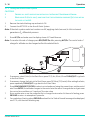
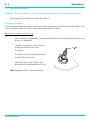
It is important that the position of the ADTS 505 in relation to the aircraft altitude sensors is
known. An altitude correction must be made to allow for the difference in height between the
reference level and the aircraft's altitude sensors (Figures 2-2 and 2-3). The Reference section
contains details of altitude correction.
WARNING: OBSERVE THE APPROPRIATE SAFETY INSTRUCTIONS AND TESTING PROCEDURES
DETAILED IN THE AIRCRAFT MAINTENANCE MANUALS AND COMPONENT
MAINTENANCE MANUALS.
K0260 Issue No. 8
Druck ADTS 505 User Manual
2- 9
FIGURE 2-2 ADTS 505 ALTITUDE CORRECTION ON-AIRCRAFT
2
FIGURE 2-3 ALTITUDE CORRECTION OFF-AIRCRAFT
K0260 Issue No. 8
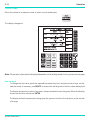
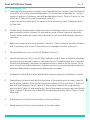
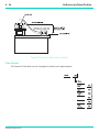
K0260 Issue No. 8
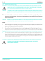
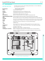
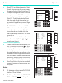
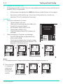
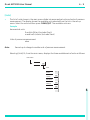
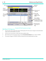
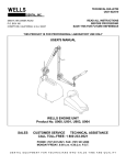
Key-pad
and display
Water
drain
Air
vent
Ground
(Earth)
stud
Power supply
connector
DO
TH NO
ES T O
E B
W V ST
D AT EN R
RE T U
AR S C
IN
T
T5.0A
250V
HBC
Power supply
switch
FIGURE 2-4 ADTS 505 GENERAL VIEW
Power supply
fuses
Hand terminal
connector (option)
Ps (static)
connector
Pt (pitot)
connector
2 - 10
Installation
Druck ADTS 505 User Manual
3
OPERATION
3.1
Preparation
3-1
WARNING:
OBSERVE SAFETY PRECAUTIONS STATED IN LOCAL ORDERS AND THE AIRCRAFT OR
EQUIPMENT SERVICING PROCEDURES.
Make sure the electrical and pneumatic connectors, electrical cables and pipes and positioning of
the ADTS 505 comply with the instructions and requirements in Section 2 Installation.
Carry out the following before use:
If necessary, carry out the maintenance task detailed in Section 4.
Make sure the air data test system power supply switch on the front panel is set to
OFF. Connect the air data test system to the electrical supply, make sure the supply
includes a connection to a protective earth.
Inspect the pneumatic hoses for damage, ingress of dirt and moisture. Make sure the
aircraft adaptors are serviceable and the pipe connections are air-tight.
Note: Do not connect the air data test system to a contaminated aircraft system. Inspect the static
vents and pitot probes for dirt and debris before connecting. If necessary, check the pitot-static
system water drain traps.
Note:
Connect, to the air data test system, the hoses necessary for the test procedures to be carried out:
STATIC output (Ps), PITOT output (Pt). Temporarily seal the free ends of the hoses.
When connected, take care not to kink or stand on the hoses.
Before use, the ADTS 505 should be tested, for first time users see section 3.4, for users requiring
more operating detail see section 3.5.
This section contains a quick reference chart detailing all the functions of the key-pad. Further
quick reference charts, at the end of this section, detail the set-up menu.
Review and become familiar with the whole procedure before starting the test process on an
aircraft or component.
K0260 Issue No. 8
3
3-2
3.2
Operation
Display Functions and Units of Measure
When operating in either pressure measuring or pressure controlling modes, the ADTS 505 can
display the following information:
Aeronautical Functions
Display Abbreviation
Displayed Units
(if applicable)
Altitude
Calibrated Airspeed
Mach
Rate of Climb
Rate of Airspeed
Pressure Functions
ALT
CAS
MACH
ROC
Rt CAS
Display Abbreviation
ft, m
kts, km/h, mph
ft/min, m/min, m/s, hm/min
kts/min, km/h/min, mph/min
Displayed Units
(if applicable)
Static (Absolute)
Pitot (Absolute)
Dynamic or Impact
(Differential)
Engine Pressure Ratio
Rate of Ps
Rate of Pt
Rate of Qc
Rate of EPR
Ps
Pt
[P]
[P]
Qc
EPR
Rt Ps
Rt Pt
Rt Qc
Rt EPR
[P]
[P] /min
[P] /min
[P] /min
EPR/min
Where [P] is the currently selected pressure units from the following list:
mbar, inHg, mmHg, inH2O (4°C), inH2O (20°C), inH2O (60°F), psi, hPa, kPa.
Operating Range and Performance
The ADTS 505 is supplied with a full-scale range of 650 knots for measurement and control of the
pitot pressure channel. The unit can measure altitude up to 105,000 ft; altitude control depends
on the performance of the pump, the integral pump is capable of achieving -2000 to 60,000 ft.
Refer to section 6 for more details of performance and specification.
Sets of factory-defined limits known as ARINC565, Standard, Military, Max and EPR can be selected
through the SETUP menu (see Reference section 6). Operators may also define up to five sets of
additional limits for different aircraft types. When configuring the display to aeronautical or
pressure units operators should be aware that when units of pressure are selected, wider full-scale
pressure limits will be enabled for some parameters.
K0260 Issue No. 8
Druck ADTS 505 User Manual
3.3
3-3
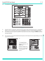
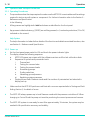
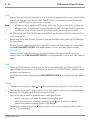
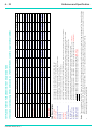
Quick Reference
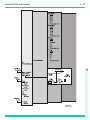
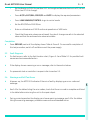
KEY-PAD FUNCTION
Key/selection
F1-F6
ALT/Ps
SPEED Qc
EPR
ROC/RATE Ps
LEAK MEASURE/CONTROL
RATE
GROUND
SETUP
HELP
0-9
-/000
CLEAR/QUIT
ENTER
DELETE
CLEAR/QUIT + DELETE =
the display shows the main pressure display (Leak Measure or Control mode) with
normal operation key functions.
Function and comments
Function keys for menus
Altitude (Aeronautical units) or Ps (pressure units)
Airspeed (Aeronautical units) or Qc (pressure units)
Engine Pressure Ratio (pressure units only)
Rate of Climb (Aeronautical units) or Rate of Ps (pressure units)
Switches between measure mode (for leak testing) and control mode
Rate of change of Pitot or Mach parameter, press parameter then RATE (read only)
Controls Ps to atmospheric pressure and Qc to zero both at current rates of change
Changes functions, limits and units, if [save/lock] pressed changes are permanent
Press HELP for further information on current selection/display
Number entry
Minus sign for first number entry 000 (thousand) if not first number of entry
Clear number entry - quit from menu, HELP screen or clear warning message
Complete number entry
Removes the last number or character entered
ABORT, all operations stop, the ADTS 505 restarts from a normal power-up
sequence, including safe equalising of pressures between the test set and the
connected system
3
100 / 120 / 230V ~ 50 / 60Hz 200VA
115V ~ 400Hz 200VA
T5.0A
250V
HBC
FIGURE 3-1 KEY-PAD AND DISPLAY
K0260 Issue No. 8
3-4
Operation
3.4
First Time Operators
The following sequences of operation should be used by first time operators and by operators that
use the equipment occasionally. For regular users, familiar with the equipment, go to section 3.5.
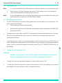
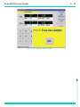
Set the power supply switch to ON and the power-on routine starts.
(1)
The display first shows:
(2)
After approximately five seconds the display shows
the start of the power-on sequence, the system
carries out a self test. If the test finds a fault, the
display shows an error message, refer to Section 5,
Fault Finding and Testing.
(3)
F1
SYSTEM STARTING
F4
F5
F6
ALT
Ps
SPEED
Qc
MACH
Pt
ROC
RATE Ps
GROUND
RATE
LEAK
MEASURE
HELP
SETUP
F1
F1
F1
F2
F2
F2
ALT
Ps
SPEED
Qc
ROC
RATE Ps
GROUND
RATE
HELP
SETUP
LEAK
MEASURE
CONTROL
MACH
Pt
Software Version 1.06
LAST CALIBRATED [DD/MM/YYYY]
F6
CHECKING FOR VACUUM LEAKS
CLEAR
QUIT
8
9
4
5
6
ABORT
1
_
2
3
DELETE
0
.
ENTER
ALT
Ps
SPEED
Qc
ROC
RATE Ps
GROUND
RATE
HELP
SETUP
LEAK
MEASURE
MACH
Pt
ADTS 505
(4)
5
6
ABORT
1
_
2
3
DELETE
0
.
ENTER
ALT
Ps
SPEED
Qc
ROC
RATE Ps
GROUND
RATE
HELP
SETUP
LEAK
MEASURE
MACH
Pt
4
5
6
ABORT
1
_
2
3
DELETE
0
.
ENTER
F1
F2
F3
F3
ADTS 505
F4
CLEAR
QUIT
9
000
CONTROL
F6
PRESSURIZING PUMPS
8
F2
ALT
Ps
SPEED
Qc
ROC
RATE Ps
GROUND
RATE
HELP
SETUP
LEAK
MEASURE
MACH
Pt
5
6
ABORT
2
3
DELETE
0
.
ENTER
F1
F2
F3
ADTS 505
F4
F4
FINDING VALVE BIAS 1 OF 4 . . .
RATE
HELP
SETUP
4
5
6
ABORT
1
_
2
3
DELETE
0
.
ENTER
000
SPEED
Qc
ROC
RATE Ps
GROUND
RATE
HELP
SETUP
LEAK
MEASURE
CONTROL
MACH
Pt
CLEAR
QUIT
7
8
9
4
5
6
ABORT
1
_
2
3
DELETE
0
.
ENTER
000
CLEAR
QUIT
1
_
F6
ALT
Ps
F5
4
000
CONTROL
GROUND SENSORS
GROUND
ENTER
F6
F6
ROC
RATE Ps
.
9
OPEN VALVES
CLEAR
QUIT
0
8
KEEP SIDE AIR VENTS CLEAR
9
DELETE
7
F5
8
ABORT
3
F4
Software Version 1.06
LAST CALIBRATED [DD/MM/YYYY]
7
F1
7
6
2
F3
F5
KEEP SIDE AIR VENTS CLEAR
MACH
Pt
5
1
_
F2
F5
SPEED
Qc
CONTROL
CLEAR
QUIT
4
4
ADTS 505
KEEP SIDE AIR VENTS CLEAR
ALT
Ps
LEAK
MEASURE
F6
CHECKING FOR PRESSURE LEAKS
9
000
CONTROL
Software Version 1.06
LAST CALIBRATED [DD/MM/YYYY]
8
9
F1
F4
F5
7
8
F3
ADTS 505
F4
F5
7
000
F3
ADTS 505
F4
CLEAR
QUIT
7
000
CONTROL
F3
F3
PLEASE WAIT
The display messages show a sequence of
pneumatic and internal system checks:
ADTS 505
Software Version 1.06
LAST CALIBRATED [DD/MM/YYYY]
THERMAL TEST PLEASE WAIT
F2
ALT
Ps
SPEED
Qc
ROC
RATE Ps
GROUND
RATE
HELP
SETUP
LEAK
MEASURE
CONTROL
MACH
Pt
F5
F6
CLEAR
QUIT
7
8
9
4
5
6
ABORT
1
_
2
3
DELETE
0
.
ENTER
000
After a successful self-test sequence the system changes to measure mode. The display changes
to the Leak Measure mode display showing the parameters selected in set-up.
K0260 Issue No. 8
Druck ADTS 505 User Manual
(5)
1
2
(6)
3-5
The system is now ready for use.
NOTES
The ADTS 505 is a continuous, self-monitoring system. If the system detects an error, the display
shows an error message. Lists of errors are detailed in Section 5, Fault Finding and Testing.
The display at power-up will be [QUAD] format (see above) unless changed in SETUP and [Save
Settings] selected.
The connection of an optional hand terminal (option A or B) causes the front panel display to show
one of two messages:
or
F1
REMOTE
HAND
TERMINAL
OPERATING
F2
F3
F4
F5
F6
ALT
Ps
SPEED
Qc
MACH
Pt
ROC
RATE Ps
GROUND
RATE
LEAK
MEASURE
CONTROL
HELP
SETUP
CLEAR
QUIT
7
8
9
4
5
6
ABORT
1
_
2
3
DELETE
0
.
ENTER
000
To change between
these two displays, see
SETUP and
[Display], [Hand Term],
[Monitor] or [Message].
See paragraphs 3.4.1
and 3.9.
K0260 Issue No. 8
3
3-6
Operation
3.4.1 Operating Modes
The air data test system can now be set for a variety of functions and modes. In the following,
examples of measure mode, control mode, leak measure mode and go-to-ground show the key
presses and selections required for each mode.
Measure Mode
The system automatically enters measure mode after a successful self-test. To change the display
press:
To set the display to show [Monitor]
or [Message] press F6. This switches
between the two settings and
operates only when the hand
terminal is connected.
To store display for the next power-up press:
To return to measure mode press:
K0260 Issue No. 8
Druck ADTS 505 User Manual
3-7
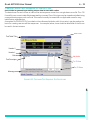
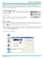
Checking the Limits
Before use on aircraft systems or components check that the limits are within the values stated
in the appropriate maintenance manual. There are sets of factory-defined limits:
Civil, Standard, Max or EPR (refer to Section 1 for details)
At each power-up sequence the default set of limits "CIVIL" become active. The "CIVIL" limit set
contains the lowest ranges and values. To see the name of the set of limits in use, press SETUP the
display shows the [name] in the F3 limits field. To see the value of limits in use proceed as follows:
User
Limits
Active Limit Set: CIVIL
STANDARD
CIVIL
Available User Limits
USER 1
USER 2
USER 3
USER 4
USER 5
ROC
RATE Ps
GROUND
LEAK
MEASURE
HELP
F1
t
MAX
SPEED
Qc
Limits
s
Available Preset Limits
ALT
Ps
Supervisor
MACH
Pt
s
F2
t
Select
Limits
F3
Select
Limit
View
Details
F4
Modify
Details
Enter
PIN
F5
Modify
Name
F6
Save
Settings
CLEAR
QUIT
7
8
9
4
5
6
ABORT
1
_
2
3
DELETE
0
.
ENTER
RATE
SETUP
000
CONTROL
The current selected limits can be viewed by pressing F3. To select and use one of the factorydefined limit sets or define one of five sets of user-defined limits, see 3.5.6. The selected set of limits
remain active until the selection of another set of limits or until power supply switch-off.
User
User
Supervisor
Details
Detail
F1
Next
Page
m km/h
m/min
F2
s
mbar
mbar/min
F3
t
F4
Modify
Units
Details
Min ALT
Max ALT
Min CAS
Max CAS
Max Mach
Max ROC
Alt Cor.
ARINC Limits
-1000 ft
50,000 ft
0.0 knots
450 knots
1.0 Mach
6,000 ft/min
0 ft
OFF
Next
Page
Page #1
ALT
Ps
SPEED
Qc
MACH
Pt
ROC
RATE Ps
GROUND
RATE
HELP
SETUP
LEAK
MEASURE
CONTROL
F5
ft kts
ft/min
F6
more
(1 of 2)
7
8
9
CLEAR
QUIT
4
5
6
ABORT
1
_
000
2
3
DELETE
0
.
ENTER
Details
Min Ps
Max Ps
Min Qc
Max Qc
Rt Ps
Rt Qc
115.97 mbar
1050.41 mbar
0.0 mbar
368.01 mbar
100.00 mbar/min
100.0 mbar/min
Next
Page
F1
F2
F3
F4
Page #2
F5
F6
more
(2 of 2)
ALT
Ps
SPEED
Qc
MACH
Pt
ROC
RATE Ps
GROUND
RATE
LEAK
MEASURE
CONTROL
HELP
SETUP
CLEAR
QUIT
7
8
9
4
5
6
ABORT
1
_
2
3
DELETE
0
.
ENTER
000
K0260 Issue No. 8
3
3-8
Operation
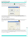
Control Mode
When the system is in measure mode, to enter control mode press:
The display changes to:
Note: The number of parameters displayed depends on the settings made in set-up, see previous page.
New set-point
To change the Aim value, press the required parameter key and, using the numeric keys, set the
new Aim value. If necessary, use DELETE to remove the last digit set in the Aim value display field.
The display shows each numeric key press, a beep sounds with each key press. When the display
shows the new Aim value press ENTER.
The display shows the parameter changing as the system controls to the set-point, at the set rate
of change.
K0260 Issue No. 8
Druck ADTS 505 User Manual
3-9
Go to GROUND
When the system is in control mode press:
Note: Go to ground does not operate in measure mode.
The ALT Aim value immediately changes to the current
ground pressure (local airfield altitude) and the system
safely controls to the GROUND value stored from
power-up. The CAS Aim value immediately changes to
zero and the system safely controls to zero:
The altitude and airspeed decreases at the rate set in
ROC and RtCAS.
When the altitude and airspeed are at ground and zero
the display changes to:
F1
SAFE
AT
GROUND
F2
F3
F4
F5
F6
ALT
Ps
SPEED
Qc
MACH
Pt
ROC
RATE Ps
GROUND
RATE
LEAK
MEASURE
CONTROL
HELP
SETUP
CLEAR
QUIT
7
8
9
4
5
6
ABORT
1
_
2
3
DELETE
0
.
ENTER
000
At ground and zero the display shows safe at ground for 5
seconds then the ADTS 505 system closes the output valves
to isolate the aircraft system and goes into a system datum
check routine (includes operation of the pump and control
valves) go to 3.7.8 for more details.
After completion of the system datum check routine the
display shows safe at ground and the message "Press Clear/
Quit to continue".
It is now safe to continue testing or to switch off and
disconnect the aircraft system.
When familiar with these procedures go to 3.5.4 to leak test
the ADTS 505.
K0260 Issue No. 8
3
3 - 10
3.5
Operation
Operation and Example Procedures
3.5.1 Operating Procedures
The procedures show the steps required to make sure the ADTS 505 is serviceable and the settings
required to test an aircraft system or component. For further information refer to the Section 6 Reference and Specification.
In the following:
All key presses are highlighted in bold and shown as identified on the front panel.
Key presses inside brackets e.g., [MORE], are soft key presses (i.e., function key selections {F1 to F6}
indicated on the screen).
Help System
The help information includes further details of the function and details associated functions, also
see Section 6 - Reference and Specification.
3.5.2 Power-up
Set the front panel power switch to ON and check the power indicator lights.
The display shows the following sequence:
a.
ADTS 505 power-up screen with the software version and the last calibration date.
b.
Sequence of system and pneumatic tests:
i.
Thermal test.
ii.
Testing for vacuum leaks.
iii.
Testing for pressure leaks.
iv.
Pressurizing pumps.
v.
Finding valve bias.
vi.
Measuring ground pressure.
vii.
Equalising system pressures.
c.
Display shows Leak Measure mode and the number of parameters last selected in
display set-up.
Make sure that the ADTS 505 performs a self-test with no errors reported refer to Testing and Fault
finding Section 5, for details of errors.
The ADTS 505 always powers up in Leak Measure mode with the pressure controllers off. When
changing to Control Mode the pump unit must be producing the correct pressure and vacuum.
The ADTS 505 system is now ready for use. After approximately 15 minutes, the system may be
used with full specification accuracy and stability.
K0260 Issue No. 8
Druck ADTS 505 User Manual
3 - 11
3.5.3 Control or Measure Parameter
To change the displayed Measure parameters:
Press SETUP [Displays], [Single, Dual, Quad], press CLEAR/QUIT repeatedly until the display goes
to Leak Measure Mode.
Measure parameters:
Press the parameter key
e.g., press SPEED/Qc to display airspeed.
To change the displayed rate parameter:
Press the associated parameter key followed by the rate key.
e.g., display airspeed rate, press SPEED/Qc then RATE.
ROC/RATE Ps may be directly pressed without first pressing ALT/Ps.
In Leak Measure mode, pressing the parameter and rate keys changes the order that the display
shows the parameters.
Control Aim
A new control aim can be entered using the numeric keys. Each digit is displayed as it is pressed.
The existing aim is replaced when the first digit of the new aim is pressed. If an error is made during
the entry of data, press CLEAR/QUIT to restore the original aim.
Press ENTER to action the new aim.
Note 1:The -/000 key can be used as a quick way of entering thousands. If this key is pressed first (i.e.
before a number is entered) the value becomes negative, press again the value becomes positive.
Note 2:The ADTS 505 must be in control mode to enter a new aim (current aim displayed). If the aim
field shows "Leak Measure" press LEAK MEASURE/CONTROL to enter control mode.
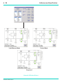
3.5.4 Leak Testing the ADTS 505
It is important to check that the ADTS 505 and the connecting hoses do not leak. Before use, a leak
check should be carried out as follows:
Connect the Pitot and static hoses (to front panel of ADTS 505). Temporarily seal the free ends of
the hoses.
Set the display to quad, see 3.4.1. Set the units to feet and knots, see 3.5.5.
K0260 Issue No. 8
3
3 - 12
Operation
Press LEAK MEASURE/CONTROL to select Control mode.
Using the set-up menu, choose the limits set for the aircraft or UUT, see 3.5.6.
Press CLEAR/QUIT repeatedly until the display shows control mode.
Set ROC/RtPs to 5000ft/min, enter an altitude aim of 1000 ft and an airspeed of 200 knots.
Wait until the system achieves the aim values and press LEAK MEASURE/CONTROL to
change to Leak Measure mode.
Leak Measurement
Note: Compressing a gas generates heat. Gas heated or cooled in an enclosed volume causes a
pressure change. It is important, especially for leak testing, to allow enough time for the heated
gas to cool and the pressure to stabilize.
In Leak Measure mode, select from the main menu [Rate Timer], and enter a wait time in minutes
and seconds F3 - [Set Wait] 00m.30Secs. Enter a leak measure time in minutes and seconds F4 [Set Time] 00m.30Secs. If necessary, press F5 to save these times for future use.
Select [Start Timer] F1, as the rate timer starts, the display shows the count down (in seconds) of
the wait time and then the count down of the timing. The status message at the bottom of the
screen changes in this order LEAK MODE: WAIT: TIMING: RATES AVAILABLE: Wait until rate timer
has completed, the rate parameters on the display changes from "Leak Measure" to "Timed Leak
Measure" and shows the results in units/min.
•
Check ROC is less than ±25 ft/min and Rt CAS is less than ±0.25 kt/min.
•
Press CLEAR/QUIT to return to the main menu.
•
Press LEAK MEASURE/CONTROL to return to Control mode.
•
Press GROUND, to go to atmospheric pressure.
•
Wait until the display shows safe at ground (atmospheric pressure).
After a successful leak test, the ADTS 505 is now ready to be connected to an aircraft system or
unit under test.
After an unsuccessful, first-time leak test, leave the system to achieve thermal stability for a further
five minutes, press CLEAR/QUIT and repeat the leak test. If the leak test is now successful, the
ADTS 505 is now ready to be connected to an aircraft system or unit under test.
After another unsuccessful leak test, disconnect both hoses, check the condition of the o-rings on
the Ps and Pt connectors as detailed in the maintenance section and firmly replace the blanking
caps. Press CLEAR/QUIT and repeat the leak test procedure.
After a successful leak test without hoses connected, replace or repair the faulty hose(s) and test
again. If the ADTS 505 fails the leak test without hoses connected, switch off and return the unit
to the repair depot.
K0260 Issue No. 8
Druck ADTS 505 User Manual
3.5.5 Changing the Units of Measurement
The units of measurement can be changed
to units of pressure measurement or
aeronautical units.
3 - 13
Main Menu
Units
F2
To change the units:
Units
•
•
•
•
•
Select, from the main menu, [Units].
Select from the Units Menu:
Select [Save Settings] to store as the
units used at the next power up.
Press CLEAR/QUIT to return to the
main pressure display.
In set-up, more units of pressure
measurement can be selected for
each parameter.
ft kts
ft/min
m km/h
m/min
mbar
mbar/min
Save
Settings
F1
F2
F3
F4
F5
F6
3.5.6 Setting Limits
All data entered is checked against minimum and maximum values set for the particular limit set
in use. If these limits are exceeded, the display shows a warning message "Changed aim to current
limit". Press CLEAR/QUIT the system automatically modifies the aim values so that the limits are
not exceeded. All limits of associated parameters are checked, if these limits are exceeded the
display shows the warning message and the parameter modified. Similarly, if an ARINC 565 limit
is exceeded when entering a value and, ARINC limits are enabled, the display shows a warning
message. Refer to Section 6 for details of the factory-defined operating envelope ARINC565.
In the SETUP function, previously stored sets of limits can be selected for use. Each set of limits is
stored under name or number up to a maximum of 10 characters. To enable other sets of limits
or enter additional sets of limits requires the supervisor PIN.
K0260 Issue No. 8
3
3 - 14
Operation
To select a limit set (User)
Press SETUP, the display shows Setup, [Limits]
[xxxxxx], where xxxxxx is the current name of
the selected limit set. Select [Limits] [xxxx] F3.
The display highlights the current set of limits
in use by the name in the list. The current limit
values can be inspected by pressing [View
Details] F4. The display shows the current
limit values and divides these values into
aeronautical (Page #1) and pressure (Page
#2).
The ARINC 565 limit can be selected ON or
OFF in a set of user defined limits, When
selected, the values entered and/or achieved
in control mode are checked within the
operating envelope of the ARINC 565 limits,
see section 6.
To select another set of limits from the list
press [Select Limits], F5. Use [ ] or [ ] to
move through the list.
To edit a limit set (Supervisor)
To edit or make a new set of limits press [Enter
PIN], F3 and enter the PIN. Use [ ] or [ ] to
move through the list. Each set of limits is
identified by it's name. New sets of limits can
be created and existing sets of limits can be
renamed or values changed. Refer to section
6 for more details. The user-named sets, can
be edited by pressing [Select Limit [xxxxxx],
then Modify Details or Modify Name.
Select [Save Settings] to store the new details
or name to be used on the next power-up of
the system.
User
Limits
Active Limit Set: CIVIL
STANDARD
CIVIL
Available User Limits
USER 1
USER 2
USER 3
USER 4
USER 5
ROC
RATE Ps
MACH
Pt
GROUND
RATE
HELP
SETUP
LEAK
MEASURE
t
Select
Limits
F3
Select
Limit
View
Details
F4
Modify
Details
Enter
PIN
F5
Modify
Name
F6
Save
Settings
7
8
9
CLEAR
QUIT
5
6
ABORT
1
_
2
3
DELETE
0
.
ENTER
User
2
For temporary changes press QUIT/CLEAR
in place of [Save Settings].
The factory-defined limit sets, “STANDARD“,
"MAX" and "CIVIL" cannot be changed.
K0260 Issue No. 8
Supervisor
Details
Details
Min ALT
Max ALT
Min CAS
Max CAS
Max Mach
Max ROC
Alt Cor.
ARINC Limits
-1000 ft
50,000 ft
0.0 knots
450 knots
1.0 Mach
6,000 ft/min
0 ft
OFF
Next
Page
Page #1
ALT
Ps
SPEED
Qc
MACH
Pt
ROC
RATE Ps
GROUND
RATE
LEAK
MEASURE
HELP
SETUP
CONTROL
F1
Next
Page
F2
s
F3
t
F4
Modify
Units
F5
ft kts
ft/min
F6
more
(1 of 2)
CLEAR
QUIT
7
8
9
4
5
6
ABORT
1
_
2
3
DELETE
0
.
ENTER
000
User
Supervisor
Limits
Details
Min Ps
Max Ps
Min Qc
Max Qc
Rt Ps
Rt Qc
0.0 mbar
1050.406 mbar
0.0 mbar
368.01 mbar
105.00 mbar/min
90.0 mbar/min
Next
Page
F1
m km/h
m/min
F2
mbar
mbar/min
F3
F4
Page #2
F5
F6
Notes:
1
s
F2
4
000
CONTROL
F1
t
MAX
SPEED
Qc
Limits
s
Available Preset Limits
ALT
Ps
Supervisor
ALT
Ps
SPEED
Qc
MACH
Pt
ROC
RATE Ps
GROUND
RATE
HELP
SETUP
LEAK
MEASURE
CONTROL
7
8
9
CLEAR
QUIT
4
5
6
ABORT
1
_
2
3
DELETE
0
.
ENTER
000
more
(1 of 2)
Druck ADTS 505 User Manual
3.6
3 - 15
Tests Before Use
Note:
It is recommended that the following test is carried out, before use, at least once per day.
1.
2.
Note:
Switch the unit ON. After the power-up routine, fit the blanking caps to the outlet ports.
Carry out the standard serviceability test in section 5.
It is recommended that, for protection, the blanking caps remain fitted to the outlet ports
until required for connection to the Pitot-Static systems.
3.6.1 Aircraft System Protection
The ADTS 505 protects the aircraft system against user error and leaks in the aircraft system. The
system protection operates:
Limit checking of all aim values entered.
Automatically regains control if the leak rate is greater than the parameter rate (RtPt, ROC)
during leak testing.
The pressure controllers within the ADTS 505 have the ability to feed a leak within an aircraft system.
When first testing an aircraft system, carry out a leak test in accordance with the aircraft
maintenance manuals.
If, during a leak test, a leak in the system produces a rate of climb greater than ±3000 ft/min or a
rate of change of airspeed greater than ±300 knots/min, then the pressure controllers automatically
regain control to minimise damage to the aircraft system. This AUTO LEAK RECOVERY facility can
be disabled.
3.7
Testing Aircraft Systems or UUT
WARNING:
OBSERVE THE APPROPRIATE SAFETY INSTRUCTIONS AND PROCEDURES DETAILED IN THE
AIRCRAFT MAINTENANCE MANUALS OR COMPONENT MAINTENANCE MANUALS.
Connect the hoses and appropriate adaptors to the aircraft system or UUT.
To make sure that the connections to the aircraft system or UUT are not leaking carry out a leak
test detailed in the appropriate aircraft or component manual.
K0260 Issue No. 8
3
3 - 16
Operation
3.7.1 Testing the Aircraft Static System
CAUTIONS:
1
OBSERVE ALL SAFETY PRECAUTIONS DETAILED IN THE AIRCRAFT MAINTENANCE MANUAL.
2
WHEN USING PS (STATIC ONLY), MAKE SURE THAT THE DIFFERENTIAL PRESSURE (QC) STAYS WITHIN
THE LIMITS OF THE ASI.
1.
2.
Remove the static blanking cap and switch ON.
Connect the ADTS 505 to the Aircraft Static System.
Note: If the static system under test contains an ASI, applying static (vacuum) to this instrument
generates a QC differential pressure.
3.
Press ALT/Ps and make sure the display shows ALT Leak Measure.
Note: To monitor the rate of change press ROC/RATE Ps after pressing ALT/Ps. The control rate of
change for altitude can be changed within the selected limits.
4.
5.
6.
7.
8.
If necessary, select [Units] in the Main Menu, press F1 [ft, kts, ft/min]. Press CLEAR/QUIT to go back
to the Main Menu.
If necessary change the limits in the Main Menu, press F6 [More], F1 [Limits]. After setting the limits,
press repeatedly CLEAR/QUIT to go back to the Main Menu.
Press LEAK MEASURE/CONTROL to select control mode and, using the numeric keys, set the control
aim. Press ENTER, the altitude changes to the control aim the rate of change slows as it gets near
the control aim and does not "overshoot" the aim value.
Enter another aim or use the nudge facility to change the aim value. At the end of testing, press
GROUND to return to atmospheric pressure.
On completion of testing, select GROUND and wait for the `Safe at Ground' message to be displayed,
see 3.7.8., refit the static blanking cap.
K0260 Issue No. 8
Druck ADTS 505 User Manual
3 - 17
3.7.2 Testing the Aircraft Pitot System
CAUTIONS:
1.
2.
3.
1
OBSERVE ALL SAFETY PRECAUTIONS DETAILED IN THE AIRCRAFT MAINTENANCE MANUAL.
2
WHEN USING PT (PITOT ONLY), MAKE SURE THAT THE DIFFERENTIAL PRESSURE (QC) STAYS WITHIN THE
LIMITS OF THE ASI.
Remove the Pitot and static blanking caps and switch ON.
Connect the ADTS 505 to the Aircraft Pitot System.
Press SPEED/Qc and make sure the display shows Qc Leak Measure.
Note: To monitor the rate of change press RATE after pressing SPEED/Qc. The control rate of change
for airspeed is fixed at 300 kts/min.
4.
5.
6.
7.
8.
If necessary, select Units in the Main Menu, press F1 [ft, kts, ft/min]. Press CLEAR/QUIT to go back
to the Main Menu.
If necessary change the limits in the Main Menu, press F6 [More], F1 [Limits]. After setting the limits,
press repeatedly CLEAR/QUIT to go back to the Main Menu.
Press LEAK MEASURE/CONTROL to select control mode and, using the numeric keys, set the control
aim. Press ENTER, the airspeed changes to the control aim the rate of change slows as it gets near
the control aim and does not "overshoot" the aim value.
Enter another aim or use the nudge facility to change the aim value. At the end of testing, press
GROUND to return to zero pressure.
On completion of testing, select GROUND and wait for the `Safe at Ground' message to be displayed,
see 3.7.8., refit the pitot and static blanking caps.
K0260 Issue No. 8
3
3 - 18
Operation
3.7.3 Combined Testing of the Aircraft Pitot and Static Systems
CAUTION:
OBSERVE ALL SAFETY PRECAUTIONS DETAILED IN THE AIRCRAFT MAINTENANCE MANUAL.
It is possible to combine the tests detailed in paragraphs 3.7.1 and 3.7.2. Any combination of altitude
and airspeed can be established within the programmed set limits.
1.
2.
Remove the pitot and static blanking caps and switch ON.
Connect the ADTS 505 to the Aircraft Pitot and Static Systems.
3.
The most convenient way of observing speed and altitude is to change the display to Dual, showing
both parameters. To observe rates of speed and altitude change the display to Quad and then, in
turn press ALT/Ps, ROC/RATE Ps, SPEED/Qc and Rate; this will display the parameters in the most
appropriate order.
If necessary, select [Units] in the Main Menu, press F1 [ft, kts, ft/min]. Press CLEAR/QUIT to go back
to the Main Menu.
If necessary change the limits press SETUP, select F3 [Limits]. After setting the limits, press
repeatedly CLEAR/QUIT to go back to the Main Menu.
4.
5.
Note: The control rate of change for altitude can be changed within the selected limits.
6.
7.
8.
Press LEAK MEASURE/CONTROL and set the ALT Aim to the required pressure and then the SPEED/
Qc CAS Aim to the required pressure.
Observe the display parameters changing as the ADTS 505 controls to the required altitude and
airspeed.
On completion of testing, select GROUND and wait for the `Safe at Ground' message to be displayed,
see 3.7.8., refit the pitot and static blanking caps.
K0260 Issue No. 8
Druck ADTS 505 User Manual
3 - 19
3.7.4 Mach Test and Constant Mach
Example
To go to 0.45 Mach, proceed as follows:
•
Press LEAK MEASURE/CONTROL to enter Control Mode.
•
Press SPEED/Qc then RATE to display rate of change of airspeed.
•
The preset rate of speed is 300 kts/min.
•
Press MACH/Pt.
•
Enter an aim of 0.45.
•
Wait for the Mach aim to be achieved.
•
The system keeps the Mach aim constant by controlling/changing Pt (pitot) leaving Ps
(static) at a constant value.
On completion of testing, select GROUND and wait for the `Safe at Ground' message to be displayed,
see 3.7.8., refit the pitot and static blanking caps.
Notes
1
If the altitude Ps (static) changes, the system automatically adjusts Pt (pitot) to keep the Mach
value constant.
2
Use the nudge facility for small changes to the Mach aim value.
3
K0260 Issue No. 8
3 - 20
Operation
3.7.5 Leak Testing
General
Apply pressure to the system under test as detailed in Testing the Aircraft Static or Pitot system.
Before starting the leak test, check that the ADTS 505 is operating within range of the set limits.
Example
To leak test a pitot system to 300 knots at a maximum rate of 300 knots/min and a static system
to 30,000 ft at a maximum rate 5,000 ft/min. Tests with a wait time of 5 minutes and test time of
1 minute. Maximum pitot system leak rate allowed 5 kts/min or less. Maximum static system leak
rate 200 ft/min or less.
Procedure
1.
Select F2 [Units], from the Main Menu, select F1 [ft, kts, kts/min]. Press CLEAR/QUIT to return to the
main menu.
2.
Press SETUP, select F1 [Display], press F3 [Quad] and then press ALT/Ps, ROC/RATE Ps, SPEED/Qc
and RATE so that the display shows these parameters in the most appropriate order.
3.
Press F3, [Rate Timer], then F3 [Set Wait 5.00], press ENTER and F4 [Set Time 1.00], press ENTER.
Press F6 to return to the Main menu.
4.
Press the LEAK MEASURE/CONTROL to enter control mode. Press ROC/RATE Ps and set an Aim of
5000 ft/min. Press ALT/Ps and set an Aim value of 30,000 ft and press ENTER. The system starts
to control to the new set-point.
5.
Press the LEAK MEASURE/CONTROL to enter measure mode. Press F1 [Rate Timer] and press F1
[Start Timing].
6.
At the end of the timing check the rate of change (leak rate) this should be within the required limits
stated in the Aircraft Maintenance Manual; in this example 200 ft/min or less.
7.
Press the LEAK MEASURE/CONTROL to enter control mode. The preset rate of speed is set at 300
knots/min. Press SPEED/Qc and set an Aim of 300 knots. The system starts to control to the new
set-point.
8.
Press the LEAK MEASURE/CONTROL to enter measure mode. Press F1 [Rate Timer] and press F1
[Start Timing].
9.
At the end of the timing check the rate of change (leak rate) this should be within the required limits
stated in the Aircraft Maintenance Manual; in this example 5 kts/min or less.
Note: If further testing is required, apply another pressure to the system under test and repeat the
steps above.
On completion of testing, press the LEAK MEASURE/CONTROL to enter control mode, select
GROUND and wait for the `Safe at Ground' message to be displayed, see 3.7.8., refit the pitot and
static blanking caps.
K0260 Issue No. 8
Druck ADTS 505 User Manual
3 - 21
3.7.6 Airspeed Switch Test
The following example shows how an airspeed switch can be functionally checked.
Note: For low airspeed switches (i.e. 130 knots) Pitot only could be used, 3.7.2.
•
Press LEAK MEASURE/CONTROL to enter control mode. Press SPEED/Qc.
•
Enter an Aim value below the operating limits of the switch (i.e., airspeed switch operating at 130
knots ±2 knots set 127 knots).
If necessary, press RATE and enter a change of airspeed low enough to observe switch operation.
Press ENTER and observe the airspeed changing.
Using the NUDGE facility, to step-increase, at a fixed increment (0.2 knots), the Aim value.
Increase the Aim until the switch operates (contacts close) and record the value.
Change the Aim to above the airspeed operating range (i.e. 133 knots). Repeat the steps, decreasing
the Aim value until the airspeed switch operates (contacts open) and record value.
On completion of testing, select GROUND and wait for the `Safe at Ground' message to be displayed,
see 3.7.8., refit the pitot and static blanking caps.
This procedure can be repeated.
The above method can be used for the other parameters:
•
•
•
•
•
•
•
•
Examples:
Altitude switch
Mach switch
-
low altitude warning
landing gear configuration warning
height lock
Speed brake scheduling
Mach cruise lock
3
K0260 Issue No. 8
3 - 22
Operation
3.7.7 Engine Pressure Ratio
The ADTS 505 may be used to check EPR sensors and indicators. Use Ps (static) for INLET pressure
and Pt (Pitot) for OUTLET pressure.
To carry out an EPR check, the display must be showing units of pressure measurement e.g., mbar,
inHg, psi.
Note: Altitude correction applies to EPR values make sure this correction does not adversely affect
accuracy. The difference in height between the ADTS 505 and the EPR sensor may be different
to the altitude correction previously set for the aircraft instruments.
To change units:
•
Press F2 [Units].
•
Select required pressure units, the pressure units are selected in set-up.
•
Use CLEAR/QUIT to return to pressure display.
To enter an EPR of 1.8 with inlet pressure of 500 mbar (15 inHg), proceed as follows:
•
If the display shows "Leak Measure", press LEAK MEASURE/CONTROL to go to control.
•
Press [Rate Inlet], F2 and set 200mbar/min.
•
Press [Rate EPR], F4 and set 0.8 EPR/min.
•
Press [Inlet], F1 set an aim value of 500 mbar (15 inHg).
•
Select [EPR] F3, set an aim value of 1.8.
•
Wait for the controller to achieve the EPR aim value. Press [Outlet], F5 to confirm 900
mbar.
Note: EPR testing can also be performed by specifying the actual INLET and OUTLET values. In the
above example, with inlet at 500 mbar, a ratio of 1.8, the outlet value should be 500 mbar x 1.8
= 900 mbar (Pt) [15 inHg x 1.8 = 27 inHg (Pt)].
Some EPR procedures (earlier ECU) may require measurement in aeronautical units:
•
Set to aeronautical units, press LEAK MEASURE/CONTROL and set the inlet pressure
(ALT control aim) to the required value.
•
Change units to pressure, press EPR, set the required ratio.
•
Allow the system to achieve the control aim. Exit EPR and return to leak measure
mode. Change units to aeronautical and record the resulting value in knots.
On completion of EPR testing, select GROUND and wait for the `Safe at Ground' message to be
displayed, see 3.7.8., refit the pitot and static blanking caps.
K0260 Issue No. 8
Druck ADTS 505 User Manual
3 - 23
3.7.8 Go To Ground
On completion of testing and, before disconnecting from the aircraft system or UUT, the pressures
in the system must be taken to the local atmospheric pressure (ground) with zero airspeed.
•
•
•
Note:
If the display shows "Leak Measure", press LEAK MEASURE/CONTROL.
Press GROUND, (go to ground).
The pressure in the system changes towards ground. The ground pressure replaces the
static or altitude aim value; zero replaces the airspeed aim.
If required, new rates of change can be entered while going to ground.
•
•
Wait for the display to show zero airspeed and atmospheric pressure.
The display changes to "safe at ground" for 5 seconds then to "aircraft safe at ground"
with the message "confirming system settings .....".
Note:
During this operation:
keep the power supply connected and switched on.
the system disables the key-pad.
it is safe to disconnect the pipes from the aircraft system or UUT.
•
•
After completing this operation the display changes back to "safe at ground" with the
message "Press Clear/Quit to continue".
It is now safe to continue testing or to switch off and disconnect the aircraft system or
UUT.
Note: If the ADTS 505 stays in the "safe at ground" for 30 minutes the
"confirming system settings ....." operation will be repeated. The
operation automatically re-checks the ADTS controller settings,
the pumps start and the display shows:
AIRCRAFT
SAFE AT
GROUND
F1
F2
F3
F4
F5
No pressure is applied to the output ports during this operation.
F6
confirming system settings 1 of 4....
ALT
Ps
SPEED
Qc
MACH
Pt
ROC
RATE Ps
GROUND
RATE
LEAK
MEASURE
CONTROL
HELP
SETUP
CLEAR
QUIT
7
8
9
4
5
6
ABORT
1
_
2
3
DELETE
0
.
ENTER
000
Shut-down
•
When the airspeed is zero and the Ps channel pressure is close to ground, the
atmospheric pressure is re-measured to update the recorded ground pressure (QFE).
•
Press QUIT/CLEAR to continue with normal operation; the ground and zero valves
automatically close.
K0260 Issue No. 8
3
3 - 24
3.8
Operation
Manual Venting of the Aircraft Pitot and Static Systems
This procedure should be carried out when the power supply has failed and the ADTS 505 has
failed-safe with pressures remaining in the aircraft system. The aircraft system pressures must be
slowly changed to atmospheric pressure in the following way:
CAUTION:
1
THE AIRCRAFT INSTRUMENTS MUST BE MONITORED THROUGHOUT MANUAL VENTING. DO NOT EXCEED THE
MAXIMUM RATES OF CHANGE OF PRESSURES FOR THE INSTRUMENTS IN THE AIRCRAFT SYSTEM. REFER TO
THE AIRCRAFT MAINTENANCE MANUAL.
2
FOLLOW THIS PROCEDURE; DO NOT PRODUCE A NEGATIVE AIRSPEED THIS WILL DAMAGE AIRCRAFT INSTRUMENTS.
i.
Using a screwdriver, carefully open the Qc manual vent and allow the pressure in the pitot
(Pt) and static (Ps) systems to equalise (shown on the aircraft ASI). Fully open the Qc valve.
Using a screwdriver, carefully open the Ps manual vent do not exceed a rate of 3000 ft/min.
When the indicated pressures, shown on the aircraft instruments, reaches atmospheric
pressure close both vents.
ii.
iii.
3.9
ADTS 505 Options
Hand Terminal Option A
The hand terminal provides the same selections and displays as the front panel display. When
connected the system auto-detects the hand terminal and disables the front panel key-pad.
The front panel display shows "Remote Hand Terminal Operating" (message/monitor) or the current
values and modes of the hand terminal (monitor). The display menu in set-up provides the selection
between message and monitor.
Advanced Hand Terminal Option B
CAUTION:
ONLY USE THIS ADVANCED HAND TERMINAL WITH ADTS 505 UNITS AT MODIFICATION STATE 3,
DAMAGE WILL OCCUR TO ADTS 505 UNITS AT EARLIER MODIFICATION STATES.
•
During the early power-up, self-test period, the instrument display screen shows:
”Software Version 1.07+”
This text is located just above the last calibration date entry.
The advanced hand terminal provides a Windows®-based, touch-sensitive colour screen to upload and down-load user-defined test programs. When connected, the system auto-detects the
advanced hand terminal and disables the front panel key-pad. The front panel display shows
"Remote Hand Terminal Operating" (message/monitor) or the current values and modes of the
advanced hand terminal (monitor). At power-up, the display shows the main operation menu with
selections for system set-up, test sequence files and manual control. See 6.4 for the details and
procedures for the advanced hand terminal.
If the ADTS 505 unit is not at the correct modification state, contact the local GE Sensing sales team
to arrange for a free upgrade of your unit.
www.ge-mcs.com
K0260 Issue No. 8
Druck ADTS 505 User Manual
3 - 25
3.10 Set-up Reference
The following charts provide a user reference for the set-up functions of the ADTS 505.
F1 Display
Display
F1 Single
F2 Dual
F3 Quad
F4 Save Settings
F5
F6 Handset [Monitor]
[Message]
F2 Units
Setup Units
F1 Alt/Ps
F2 ROC/RatePs
F3 CAS/Qc
Rt CAS/Qc
F4 Mach/Pt
Rate Pt
Alt/Ps
F1 ft
F2 m
F3 mbar
F4 “Hg
F5 psi
F6 more (1 of 3)
Alt/Ps
F1 ft
F2 “H2O°C4
F3 “H2O°C20
F4 “H2O°F60
F5 kPa
F6 more (2 of 3)
Alt/Ps
F1 hPa
F2
F3
F4
F5
F6 more (3 of 3)
ROC/Rt Ps
F1 ft/min
F2 m/min
F3 m/s
F4 hm/min
F5 mbar/min
F6 more (1 of 3)
ROC/Rt Ps
F1 “Hg/min
F2 psi/min
F3 mmHg/min
F4 “H2O°C4/min
F5 “H2O°C20/min
F6 more (2 of 3)
ROC/Rt Ps
F1 “H2O°F60 /min
F2 kPa/min
F3 hPa/min
F4
F5
F6 more (3 of 3)
CAS/Qc
F1 kts
F2 km/h
F3 mph
F4 mbar
F5 “Hg
F6 more (1 of 3)
CAS/Qc
F1 psi
F2 mmHg
F3 “H2O°C4
F4 “H2O°C20
F5 “H2O°F60
F6 more (2 of 3)
CAS/Qc
F1 kPa
F2 hPa
F3
F4
F5
F6 more (3 of 3)
Mach/Pt
F1 Mach
F2 mbar
F3 “Hg
F4 psi
F5 mmHg
F6 more (1 of 2)
Mach/Pt
F1 “H2O°C4
F2 “H2O°C20
F3 “H2O°F60
F4 kPa
F5 hPa
F6 more (2 of 2)
to (1 of 3)
to (1 of 3)
to (1 of 3)
to (1 of 2)
F5
F6 Save Settings
Continued …
K0260 Issue No. 8
3
3 - 26
K0260 Issue No. 8
Operation
Druck ADTS 505 User Manual
3 - 27
3
K0260 Issue No. 8
3 - 28
K0260 Issue No. 8
Operation
Druck ADTS 505 User Manual
4
MAINTENANCE
4.1
Introduction
4- 1
This section details the maintenance tasks to be carried out by the operator. The
maintenance chart shows the maintenance tasks, the periodicity of each task and a code
referenced to the task detailed in 4.3.
Task
Code
Period
Inspect
A
Daily, before use.
Inspect
B
Weekly
Test
C
Before use.
Test
D
Daily, before use.
Calibrate
E
Every 12 months *
Replace
F
As detailed in fault finding or when detailed after inspection.
Clean
G
Weekly *
Service
H
1,000 hours recorded by the unit's operational timer or the
equipment running log.
Service
J
3,000 hours recorded by the unit's operational timer or 1000 hours
recorded by pump operational timer or the equipment running log.
* Periodicity may change depending on usage and environment, refer to the Engineering Authority.
TABLE 4-1 MAINTENANCE CHART
4
Waste Electrical and Electronic Equipment directive 2002/96/EC
Do not dispose of this product as household waste. Use an approved
organisation that collects and/or recycles waste electrical and electronic
equipment. For more information, contact one of these:
•
our customer service department:
Contact us at www.ge-mcs.com
•
your local government office.
K0260 Issue No. 8
4-2
4.2
Maintenance
Materials and Tools
This section provides lists of the materials and tools required for the user to maintain the ADTS 505.
Item
Number
Item Name, Description
1
Cloth, Cotton, Lint-free
2
Alcohol, Isopropyl (MIL-A-10428, Grade A)
3
Detergent, Mild, Liquid
4
Brush, Soft-bristle (MIL-B-43871)
Note: Equivalent substitutes can be used.
TABLE 4-2 MATERIALS LIST
Ref Code
1
2
Nomenclature
Voltmeter, Digital
Insulation Tester, 250V
Manufacturer’s
part number
GE DPI620
Robin
Note: Equivalent substitutes can be used.
TABLE 4-3 TOOL AND TEST EQUIPMENT REQUIREMENTS
K0260 Issue No. 8
Druck ADTS 505 User Manual
4- 3
4.3
Maintenance Tasks
A
Check that all the equipment is present; record any deficiencies. Visually inspect the external
of the ADTS 505, and its associated equipment, for obvious signs of damage, dirt, and the
ingress of moisture. If necessary, use mild liquid detergent (item 3, Table 4-2) and a lint-free
cloth (item 1, Table 4-2) to clean the external surfaces.
Inspect the pressure outlet ports for ingress of dirt and moisture, clean if necessary with a
lint-free cloth.
B
Visually inspect the pneumatic output connectors for damage. Inspect the small o-ring on
each pneumatic output connector for cuts and any signs of wear; replace as necessary.
Visually inspect pneumatic hoses, electrical cables for cuts, splits and damage; replace as
necessary.
C
Before use, power-up the unit as detailed in Section 3. Check the date of the last calibration
and, if necessary, refer to task E. Record any error messages and refer to Section 5.
D
Daily and before use, carry out the SST detailed in Section 5.
E
Normal calibration period 12 months. When calibration is due, the unit should be withdrawn
from service and returned to depot or calibration facility. The date of calibration is stored in
the unit and displayed in the power-up sequence and on a label on the front panel. Do not
use a unit with out-of-date calibration. Engineering authority may change the periodicity of
calibration depending on usage and the operating environment.
F
As detailed in fault finding or when detailed after inspection replace the listed item in A and B.
G
Depending on the level of use and the cleanliness of the operating environment, clean the
unit at regular intervals. Clean the front panel with a damp lint-free cloth (item 1, Table 4-2)
and mild liquid detergent (item 3, Table 4-2). Remove any stubborn dirt using isopropyl
alcohol (item 2, Table 4-2) and allow to dry. Clean all pneumatic connectors with a soft brush
(item 4, Table 4-2). Remove any stubborn dirt using isopropyl alcohol (item 2, Table 4-2) and
allow to dry.
H
Withdraw the unit from service and return to the repair depot.
J
Withdraw the unit from service and return to the repair depot.
K0260 Issue No. 8
4
4-4
4.4
Maintenance
Routine Maintenance
WARNING: SWITCH OFF AND DISCONNECT THE POWER SUPPLY BEFORE STARTING ANY MAINTENANCE TASK.
Carrying out the maintenance tasks detailed 4.3.
Servicing Procedures
The following procedures provide instructions to test and replace items for the operator. Return the
unit to the repair depot for further testing and replacement of items.
Replacing the output connector o-ring
After inspection as detailed in maintenance task B, carry out the following if the o-ring
is worn or damaged:
Carefully remove the o-ring from the
small groove at the top of the
connector.
Fit a new o-ring in the small groove at
the top of the connector.
Make sure the o-ring is tight in the
groove and not damaged after fitting.
Note: Damage to this o-ring causes leaks.
K0260 Issue No. 8
Druck ADTS 505 User Manual
4- 5
Fuse Replacement (Fig 4-1)
Replace the fuse when detailed in Section 5, Testing and Fault Finding:
•
Set the power switch to OFF.
Note: The power switch is not a power isolator as defined by EN61010.
•
Isolate the power supply to the instrument by disconnecting the power supply
connector (1).
•
Unscrew and remove the fuse cap (2) and fuse cartridge (3) from the front panel and
replace the fuse cartridge (3).
Note: Fit the correct type of fuse detailed in Section 2, Installation and on the front panel.
•
Refit the fuse cap (2) and fuse cartridge (3) to the front panel.
•
Reconnect power supply connector (1).
•
Switch on the power supply. The instrument should now be operational.
•
If a fuse blows immediately on switch-on, contact the manufacturer or Service Agent.
2
3
1
4
FIGURE 4-1 FUSE REPLACEMENT
K0260 Issue No. 8
4-6
Maintenance
Hand Terminal Cable Tests
Carry out the following check as detailed in Testing and Fault Finding, Section 5.
Measure continuity using the DVM (item 1, Table 4-3) set to an appropriate range.
Measure the continuity between corresponding pins at each end of each cable assembly.
É
The measured resistance must not exceed 0.10 .
Measure insulation using the Insulation tester (item 2, Table 4-3), set to an appropriate
range.
Measure the insulation resistance between the shell of the connector and all individual pins
in turn.
Measure the insulation resistance between the shell of the appropriate connectors and all
pins in turn.
Measure also the resistance between individual pairs of pins (i.e., 1-2, 1-3, 1-4, 1-5, 1-6, 23, 2-4, 2-5, 2-6, 3-4, 3-5, 3-6, 4-5, 4-6 and 5-6). In all cases the resistance must exceed 10
Mohms.
K0260 Issue No. 8
Druck ADTS 505 User Manual
5- 1
5
TESTING AND FAULT FINDING
5.1
Introduction
The ADTS 505 contains a built-in, self-test and diagnostic system. The system continuously
monitors the performance of the unit and at power-up carries out a self-test. Warning and
error messages are displayed during normal operation if out of range values are entered or if
faults occur.
This section details the standard serviceability test and the possible error messages and
codes that can be displayed. A fault diagnosis flow chart and table provide the probable
cause and procedures to rectify specific symptoms.
Error messages
When the display shows a message indicating entry of incorrect data or values, pressing
CLEAR/QUIT clears the message and allows the correct entry to be made.
5
K0260 Issue No. 8
5-2
Testing and Fault Finding
5.2
Standard Serviceability Test
The following procedure shows if the unit is serviceable and checks functions and facilities of
the ADTS 505. In this procedure:
•
All key presses are highlighted in BOLD and shown as identified on the front panel.
•
Key presses inside brackets e.g., [Units], are soft key presses (i.e., function key
selections {F1 to F6} indicated on the screen).
Procedure
Connection and power-on checks.
•
Connect power to the unit.
•
Make sure the blanking caps are fitted to the
Ps and Pt front panel outputs.
•
Set the power supply switch to ON.
•
Check power indicator is on.
•
Check the display shows the first power-up
message.
Check the display all the power-up messages.
•
F1
SYSTEM STARTING
F3
PLEASE WAIT
F4
F5
F6
ALT
Ps
The ADTS 505 displays any detected errors,
refer to fault finding.
Check that the display then changes to show
measured aeronautical or pressure values. This
depends on the display set-up.
•
F2
SPEED
Qc
ROC
RATE Ps
MACH
Pt
GROUND
LEAK
MEASURE
CLEAR
QUIT
7
8
9
4
5
6
ABORT
1
_
2
3
DELETE
0
.
ENTER
RATE
HELP
SETUP
000
CONTROL
F1
F1
F1
F2
F2
F3
ADTS 505
F4
SPEED
Qc
MACH
Pt
ROC
RATE Ps
GROUND
RATE
LEAK
MEASURE
CONTROL
HELP
SETUP
CLEAR
QUIT
7
8
9
4
5
6
ABORT
1
_
2
3
DELETE
000
0
.
F5
CHECKING FOR VACUUM LEAKS
ALT
Ps
SPEED
Qc
ROC
RATE Ps
GROUND
RATE
HELP
SETUP
LEAK
MEASURE
ENTER
7
MACH
Pt
8
9
5
6
ABORT
2
3
DELETE
.
ALT
Ps
CLEAR
QUIT
1
_
0
F4
Software Version 1.06
LAST CALIBRATED [DD/MM/YYYY]
F5
CHECKING FOR PRESSURE LEAKS
F6
ADTS 505
ROC
RATE Ps
LEAK
MEASURE
SPEED
Qc
MACH
Pt
GROUND
RATE
HELP
SETUP
7
8
9
CLEAR
QUIT
4
5
6
ABORT
1
_
2
3
DELETE
0
.
ENTER
000
CONTROL
F4
Software Version 1.06
LAST CALIBRATED [DD/MM/YYYY]
ALT
Ps
SPEED
Qc
ROC
RATE Ps
GROUND
RATE
HELP
SETUP
LEAK
MEASURE
ENTER
MACH
Pt
8
9
4
5
6
ABORT
1
_
2
3
DELETE
0
.
ENTER
000
CONTROL
K0260 Issue No. 8
F1
F1
F5
OPEN VALVES
ALT
Ps
ROC
RATE Ps
LEAK
MEASURE
CONTROL
SPEED
Qc
MACH
Pt
GROUND
RATE
HELP
SETUP
ADTS 505
7
9
CLEAR
QUIT
4
5
6
ABORT
1
_
2
3
DELETE
0
.
ENTER
000
ALT
Ps
ROC
RATE Ps
LEAK
MEASURE
CONTROL
F4
KEEP SIDE AIR VENTS CLEAR
F5
KEEP SIDE AIR VENTS CLEAR
GROUND SENSORS
F6
FINDING VALVE BIAS 1 OF 4 . . .
F6
8
F3
ADTS 505
F4
F4
KEEP SIDE AIR VENTS CLEAR
F2
F3
F3
ADTS 505
F1
F2
F2
SPEED
Qc
MACH
Pt
GROUND
RATE
HELP
SETUP
7
8
9
CLEAR
QUIT
4
5
6
ABORT
1
_
2
3
DELETE
0
.
ENTER
000
ALT
Ps
SPEED
Qc
ROC
RATE Ps
GROUND
RATE
HELP
SETUP
LEAK
MEASURE
CONTROL
MACH
Pt
F5
F6
CLEAR
QUIT
7
8
9
4
5
6
ABORT
1
_
2
3
DELETE
0
.
ENTER
000
F6
CLEAR
QUIT
7
NOTES
1 The displayed values change as atmospheric pressure changes at power-up.
2 The unit requires
15 minutes to
warm-up to
achieve full
accuracy and
stability.
F5
PRESSURIZING PUMPS
F6
4
000
CONTROL
F3
ADTS 505
F4
Software Version 1.06
LAST CALIBRATED [DD/MM/YYYY]
F5
F6
ALT
Ps
F2
F3
F3
ADTS 505
Software Version 1.06
LAST CALIBRATED [DD/MM/YYYY]
THERMAL TEST PLEASE WAIT
F1
F2
Druck ADTS 505 User Manual
5- 3
•
Set the display to QUAD format (see 3.4.1 to change) and aeronautical units of ft, kts and
ft/min (see 3.5.5 to change).
•
Press ALT/Ps, ROC/RtPs, SPEED/Pt and RATE to display the required parameters.
•
Press LEAK MEASURE/CONTROL to go to control mode.
•
Set the ROC/RtPs to 5000 ft/min.
•
Enter an altitude aim of 500 ft and an airspeed aim of 400 knots.
•
Check that these aim values are achieved, the rate of change are within the selected
rates and that the achieved aim values are stable.
Completion
Press GROUND, wait until the display shows `Safe at Ground'. On successful completion of
this test procedure, switch off and disconnect the power supply.
5.3
Fault Diagnosis
If a fault occurs, refer to the fault location chart, Figure 5-1 and Table 5-1 for possible fault
causes and recommended action.
If the display shows a warning or error message, refer to the section below.
If a pneumatic leak or controller is suspect refer to section 5.5.
5.4
Warnings and Self-Test Errors
At power-up, the ADTS 505 indicates if there is a fault by displaying an error code and
message.
See 5.6 for the tables listing the error codes, check that the error code is complete and listed
in the table before returning the unit to the repair depot.
During normal operation the display can show a warning message, see 5.6 for the tables
listing the warning messages, probable cause and recommended action.
K0260 Issue No. 8
5
5-4
Testing and Fault Finding
FIGURE 5-1 FAULT FINDING CHART
K0260 Issue No. 8
Druck ADTS 505 User Manual
5- 5
TABLE 5-1 FAULT FINDING
Fault
Symptom
Probable cause
Power supply indicator
does not light.
Faulty power supply outlet.
Check power supply.
Unserviceable power supply front Check/replace fuse.
panel fuse.
Check/replace fuse.
Faulty power supply cable.
Replace cable and re-test.
F1
Internal power supply fault.
Action
Record fault and return ADTS 505
to depot for repair.
F2
Power supply indicator
lights, no display.
Internal fault.
Record fault and return ADTS 505
to depot for repair.
F3
No self-test message.
Internal fault.
Record fault and return ADTS 505
to depot for repair.
F4
Display shows error
message.
Error detected.
Refer to fault finding tables.
If display stops at Thermal Test.
F5
Display does not show
Leak Measure mode.
Allow ADTS 505 to reach ambient
temperature.
System component fault.
Record fault and return ADTS 505
to depot for repair.
F6
Fails SST.
Internal leak.
Internal fault.
Refer to further testing 5.5.
5
K0260 Issue No. 8
5-6
5.5
Testing and Fault Finding
Further Testing
The following tests should only be carried out if a pneumatic leak or a controller instability is
suspected.
Test Environment and Preliminary Operations
These tests should be carried out in a room with a stable temperature environment within
the operating temperature range. The room must be free from drafts.
Review and become familiar with the whole of the test procedure before beginning the test
procedure.
The unit must be thermally stable; switch on and leave the unit for at least one hour to
achieve thermal stability.
Make sure the blanking caps are fitted to the Ps and Pt front panel outputs.
Change the units to mbar as follows:
(1)
Select [UNITS] then select mbar and mbar/min.
(2)
Select [Save/Lock] and then press CLEAR/QUIT and the display now shows ALT/Ps and
Speed/Qc in units of mbar.
Change the pressure limits to MAX as follows:
(1)
Press SETUP then select [LIMITS].
(2)
Use [ ] or [ ] to move through the list and press F3 to select MAX limits.
K0260 Issue No. 8
Druck ADTS 505 User Manual
5- 7
On-screen Assessment (Figure 5-2)
This procedure enables real time assessment of the system. Each valve and transducer is
characterized to obtain maximum performance. Any values shown on the screen are an
indication and not a precise value.
To assess the system, enter a set-point and a rate so that achieving the set-point takes at
least 5 minutes. Once set and controlling, select setup and display the system data screen
using the menu selection below
SETUP
Setup
(1 of 2)
F6
Setup
Maintain
Calibration
F4
Maintenance
View
Manifold
F2
5
FIGURE 5-2 SYSTEM SCREEN FOR DIAGNOSIS
K0260 Issue No. 8
5-8
Testing and Fault Finding
Data Identifier
Function
RPT Diagnostics
Ps/Altitude Sensor
RPT Diode [mV]
Temperature Compensation
RPT Count
TEMP [c]
PDCR Diagnostics
Expected Display or Value
400 (hot) ............. 800 (cold)
Value proportional to pressure
248,553 .............4,473,600
Ps channel (RPT) measured temperature
5°...... 60°C (over permitted ambient range)
Qc/Airspeed Sensor
PDCR Vc [mV]
Temperature Compensation
980 ............. 2100
PDCR Vd [mV]
Value proportional tp pressure
0 to 140 mV (always active)
Valve Diagnostics
Ps Output
Pt Output
Ground
Qc Zero
Pressure Ps
Pressure Output and Control
Ps Port isolation valve state
L:L <—> H:H (open) —:— (closed)
Pt Port isolation valve state
L:L <—> H:H (open) —:— (closed)
Ground pressure sense valve state
—:— (closed, normal), H:H (at ground)
Qc auto-zero valve state
—:— (closed, normal), H:H (at ground, auto-zero)
Ps pressure valve drive level
0 (Leak/Measure), varying to 9999 (control)
Vacuum Ps
Ps vacuum valve drive level
0 (Leak/Measure), varying to 9999 (control)
Pressure Pt
Pt pressure valve drive level
0 (Leak/Measure), varying to 9999 (control)
Vacuum Pt
Pt vacuum valve drive level
0 (Leak/Measure), varying to 9999 (control)
Pump Diagnostics
Controller Source Pressures
Pressure
Pressure pump drive state
POV (Pressure On Flow) or blank (pump off)
Vacuum
Vacuum pump drive state
VOF (Vacuum On Flow) or blank (pump off)
Processed information
Major Measurement/Control Parameters
Ps
Ps Channel Pressure, mbar absolute
0 to 1355
Qc
Qc Channel Pressure, mbar differential
-1355 to 2490
Pt
Pt Channel Pressure, mbar absolute
0 to 3845
ground
Ambient pressure estimate
800 to 1300
Ps VOL
System Ps volume estimate
0.125 (min) varies with connected system
Pt VOL
System Pt volume estimate
0.125 (min) varies with connected system
Characterisation
Control Valve Data
PWM PPS VB
Valve bias (VB) calculated in real time
Variable with temperature
PWM PPS ERR
Determined during manufacture or service operations
Constant
PWM VPS VB
Valve bias (VB) calculated in real time
Variable with temperature
PWM VPS ERR
Determined during manufacture or service operations
Constant
PWM PPT VB
Valve bias (VB) calculated in real time
Variable with temperature
PWM PPT ERR
Determined during manufacture or service operation
Constant
PWM VPT VB
Valve bias (VB) calculated in real time
Variable with temperature
PWM VPT ERR
Determined during manufacture or service operations
Constant
Tertiary Information
CAL:
DUMP:
Other system control states
Calibration lock switch state
Disabled (normal)
Pump pressure vent state
Shut (normal)
TABLE 5-2 SYSTEM SCREEN INFORMATION
K0260 Issue No. 8
Druck ADTS 505 User Manual
5- 9
5
Schematic shown on the advanced hand terminal
FIGURE 5-3 SYSTEM SCHEMATIC
K0260 Issue No. 8
5 - 10
Testing and Fault Finding
Key-pad Testing
The front panel key-pad and the hand terminal key-pad can be tested using the facility in the
maintenance/calibration selection of the set-up menu.
The procedure to test the key-pad requires each key to be pressed in turn and to confirm the
correct key press on the display. Make sure the display shows only the appropriate key press.
Note:
Connecting the hand terminal disables the front panel key-pad.
FIGURE 5-4 KEY-PAD TEST DISPLAY
K0260 Issue No. 8
Druck ADTS 505 User Manual
5 - 11
Pressure leak check
This procedure verifies that the unit is leak tight under positive pressure conditions.
(1)
Press LEAK MEASURE/CONTROL to enter control mode.
(2)
Enter an ALT/Ps Aim of 1016 mbar.
(3)
Enter a SPEED/Qc Aim of 272 mbar. Wait for the aim values to be achieved then wait
for 1 min.
(4)
Press LEAK MEASURE/CONTROL to return to Leak Measure mode.
(5)
Select [Rate Timer] and select [Set Wait 05:00], [Set Time 01:00] and then select [Start
Timing].
(6)
At the end of the timing period, the display shows the rate of change of Ps, Qc and Pt.
(7)
Check that the Ps, Qc and Pt rates are less than or equal to ±0.5 mbar/min. If the leak
rate is not achieved, allow further thermal stabilization time and re-test by selecting
[Rate Timer] and selecting [Set Wait 05:00], [Set Time 01:00].
(8)
Press CLEAR/QUIT to exit rate timer display.
5
K0260 Issue No. 8
5 - 12
Testing and Fault Finding
Vacuum leak check
This procedure verifies that the unit is leak tight under vacuum conditions.
(1)
Press LEAK MEASURE/CONTROL to enter control mode.
(2)
Enter an ALT/Ps Aim of 100 mbar.
(3)
Enter a Speed/Qc Aim of 0 mbar.
(4)
Wait the required time for temperature stabilization e.g., one minute. Press LEAK
MEASURE/CONTROL return to Leak Measure mode.
(5)
Select [Rate Timer] and select [Set Wait 05:00], [Set Time 01:00] and then select [Start
Timing].
(6)
At the end of the timing period, press ROC/RtPs to display the measured rate of change
of ALT/Ps.
(7)
Check that the Ps, Qc and Pt rates are less than or equal to ±0.5 mbar/min. If the leak
rate is not achieved, allow further thermal stabilization time and re-test by selecting
[Rate Timer] and select [Set Wait 05:00], [Set Time 01:00].
(8)
Press CLEAR/QUIT to exit rate timer display.
Range check
Control the Ps and Qc pressures to the normal limits of operation and make sure that these
are achieved. Use minimum Ps and zero Qc and then maximum Ps and maximum Qc.
Note:
K0260 Issue No. 8
Do not exceed the maximum Pt as shown on the front panel of the unit. Use
maximum available rates of change to minimise test times.
Druck ADTS 505 User Manual
5 - 13
Controller Stability
This section verifies the control stability.
(1)
Press LEAK MEASURE/CONTROL to turn the pressure controllers on.
(2)
Enter an ALT/Ps Aim of 510 mbar with a rate of change of 204 mbar/min.
(3)
Enter a Speed/Qc Aim of 0 mbar with a rate of change of 204 mbar/min.
(4)
Press ALT/Ps and wait for the aim values to be achieved.
(5)
Observe the measured values of Ps and Qc on the display for 1 min.
(6)
Check that the displayed value of Ps remains within ±0.068 mbar.
(7)
Check that the displayed value of Qc remains within ±0.068 mbar.
5
K0260 Issue No. 8
5 - 14
5.6
Testing and Fault Finding
Fault Finding
System Messages
In the event of a malfunction, the built-in, self-test and diagnostic system displays a message
and a code. The message heading Error indicates a fault or condition that interrupts normal
operation. The following tables list the error messages with the probable cause and action to
be taken.
If the display shows a message not listed in the tables the unit must be switched off. If the
display shows the same non-operational message after switching on, the unit should be
returned to the repair depot.
No.
Message
Probable Cause
Action
7
Autoleak recovery
activated
Excessive leak rate detected in Ps/Qc Check hoses and aircraft systems for
pressures
leaks
31
Test set must be at ground Invalid user request
32
Pressure leak in Ps.
Leaking Ps channel pressure control
Return unit to repair depot.
valve.
33
Pressure leak in Pt.
Leaking Pt channel pressure control
valve.
Return unit to repair depot.
36
Ps Aim Overshoot.
Connected system leak rate
changing.
Check hoses and aircraft systems for
leaks.
37
"Ps aim value
unobtainable".
Leak rate on Ps too high to control.
Check port caps, hoses and
connectors for leaks.
40
Pt Aim Overshoot.
Connected system leak rate
changing.
Check hoses and aircraft systems for
leaks.
41
"Pt aim value
unobtainable".
Leak rate on Pt too high to control.
Check port caps, hoses and
connectors for leaks.
4
Vacuum leak in Ps.
Leaking Ps channel vacuum control
valve.
Return unit to repair depot.
4
Vacuum leak in Pt.
Leaking Pt channel vacuum control
valve.
Return unit to repair depot.
4
Ps pressure control valve
cannot be calibrated.
Valve fault.
Return unit to repair depot.
56
Stabilising Qc to Zero.
Possible negative airspeed detected, System zero valve opened to stop
possible sudden leak.
negative airspeed condition.
57
Current Pressure Limits
Exceeded.
Limits for Ps or Qc exceeded.
Select Go to Ground first
Make sure pressures are within limits,
check leak rates.
TABLE 5-3 ERROR MESSAGES
Note: In No. 56, this safety feature opens the zero valve. If this happens constantly, check for leaks.
K0260 Issue No. 8
Druck ADTS 505 User Manual
No.
5 - 15
Message
Probable Cause
Action
219
Abort sequence started by user
Abort key pressed on
hand terminal
Wait until system completes abort
sequence
220
"Cannot Modify Altitude
Correction in Pressure Units"
Altitude Correction
Change units in setup to aero units
221
"Changed Aim to ARINC Limit"
Value out of ARINC limit
Re-enter value within allowed range
range
222
Calibration data failed
Incorrect pressure
value entered during
calibration
223
"Cannot enter EPR in Aero Units"
EPR selected with aero Change units in setup to pressure
units displayed
units then select EPR
227
"Changed Aim to Current Limit"
Value out of limit range Re-enter value within allowed range
228
"Limit Overlap"
Value conflicts with
limit ranges
229
"Limit Saved"
Value out of acceptable
Re-enter value within allowed range
range
241
"Ground Request in Leak Mode"
System must be in
control mode
243
"LDK has an invalid EEPROM
archive"
Invalid/corrupted data
- recovery in progress Check custom limit sets not lost
245
"Controller has an invalid EEPROM Invalid/corrupted data
archive"
- recovery in progress Check/correct calibration
247
"Handset has an invalid EEPROM Invalid/corrupted data
archive"
- recovery in progress
250
"Vacuum pump processor has
failed"
Internal fault
Return unit to repair depot
251
"Vacuum pump lead is
disconnected"
-
Return unit to repair depot
252
"Vacuum pump transistor is faulty
Internal fault
or drive inhibited"
Check and enter correct pressure
value for reference pressure point
Re-enter value within allowed range
Select control mode
Return unit to repair depot
TABLE 5-3 ERROR MESSAGES (CONTINUED)
K0260 Issue No. 8
5
5 - 16
Testing and Fault Finding
No.
253
254
255
256
Message
Probable Cause
"Vacuum pump has stalled"
"Pressure pump processor has
failed"
"Pressure pump lead is
disconnected"
"Pressure pump transistor is
faulty or drive inhibited"
Internal mechanical fault
Restart system, if fault repeats
-return unit to repair depot
Internal fault
Return unit to repair depot
-
Return unit to repair depot
Internal fault
Return unit to repair depot
257
"Pressure pump has stalled"
260
"Connected handset has failed to Handset bad connection or
respond. Disconnecting power." comms/power supply fault
261
262
Internal mechanical fault
300
309
312
313
Restart system, if fault repeats
- return unit to repair depot
Check connections and restart,
if fault repeats - return unit to
"Calibration switch has not
Switch not selected
Set calibration switch
enabled."
"Valve characterisation data is Invalid/corrupted data, recovery Allow for complete recovery
invalid. Restoring from FLASH." in progress
before continuing
263 to
"Valve constant out of range”
Essential system data failure
290
"Limit entry changed to MAX limit User tried to enter limit out of
293
set"
range of instrument
Differential pressure applied at
295 "CAS is outside MAX limits"
Ps/Pt ports over-range
Pressure applied at Ps port over296 "Alt is outside MAX limits"
range
Rate of pressure change at Ps port
297 "ROC is outside MAX limits"
too high
Differential pressure applied at
298 "Qc is outside MAX limits"
Ps/Pt ports over-range
299
Action
"Ps is outside MAX limits"
"RtPs is outside MAX limits"
Pressure applied at Ps port overrange
Rate of pressure change at Ps port
too high
"Hand terminal short circuit"
Faulty cable or hand terminal
"RtCAS is fixed and cannot be
altered"
"Calibration data not entered.
Enter calibration date"
User attempted to enter
alternative RtCAS aim
Date entry step missed in
calibration procedure
TABLE 5-3 ERROR MESSAGES (CONTINUED)
K0260 Issue No. 8
Return unit to repair depot
Re-enter within maximum
range of instrument
Check/reduce Ps/Pt pressure
applied to ADTS 505
Check/reduce Ps pressure
applied to ADTS 505
Check/correct hose or aircraft
system Ps leak
Check/reduce Ps/Pt pressure
applied to ADTS 505
Check/reduce Ps pressure
applied to ADTS 505
Check/correct hose or aircraft
system Ps leak
Check cable, if necessary,
replace hand terminal
None, RtCAS is pre-set and
locked at 300kts/min
Enter date field requested
Druck ADTS 505 User Manual
5 - 17
Additional Messages
Internal temperature
The temperature sensor in the pressure measurement system measures the temperature of
the pressure manifold. At a temperature greater than 60°C the sensor triggers an overheat
fault. In measure mode, the display flashes between the normal aim/measure screen and
"Ps Sensor Outside Calibrated Range". In control mode, the display shows "CONTROL
HALTED" the system stops controlling and switches off the pumps. When the sensor detects
a temperature of 55°C the display stops flashing.
Before re-entering control mode check the air vents for obstructions. To re-enter control
mode press LEAK MEASURE/CONTROL twice. If this overheat fault happens again switch off
the unit and return to repair depot.
5
K0260 Issue No. 8
5 - 18
Testing and Fault Finding
Intentionally left blank
K0260 Issue No. 8
Druck ADTS 505 User Manual
6
REFERENCE AND SPECIFICATION
6.1
Introduction
6- 1
This section includes a full description of each key-pad selection and function, the main
menu selections and functions and set-up selections and functions.
The available keys are:
F1 - F6
ALT Ps
SPEED Qc
MACH Pt
ROC Ps RATE
RATE
LEAK MEASURE/CONTROL
GROUND
HELP
SETUP
0 to 9
- 000
CLEAR/QUIT
DELETE
ENTER
.
Double key press:
ABORT (CLEAR/QUIT + ENTER)
6.2
Key-pad Selections and Functions
F1 - F6
These function keys or soft-keys are used to select choices from menus. The main menu
choices are shown next to the keys. After making a menu choice, the display shows further
selections in a sub-menu or the display changes indicating a successful selection.
When a sub-menu is displayed, press the appropriate function key to select the required
choice.
CLEAR/QUIT can be used to leave a sub-menu without making a selection.
K0260 Issue No. 8
6
6-2
Reference and Specification
ALT Ps
•
In aeronautical units (ft or m), this key selects an altitude display.
•
In pressure units (mbar, inHg etc.), this key selects a static pressure (Ps) display.
•
Select [Units], from the main menu, to change the display units.
•
Before entering a new altitude or Ps aim, set the rate of change using the ROC/RATEPs key.
•
When in Control Mode (Aim display), enter a new altitude or Ps aim using the numeric keys.
Use LEAK MEASURE/CONTROL to change between Control and Leak Measure mode.
SPEED Qc
•
In aeronautical units (kts, km/h), this key selects an airspeed (CAS) display. In pressure units
(mbar, inHg etc.), this key selects dynamic pressure and the display shows (Qc).
Note: For testing purposes, Calibrated Airspeed (CAS) equates to Indicated Airspeed (IAS).
•
If the altitude aim is changed, after the entry of CAS, the Mach aim value changes while the
CAS value remains unchanged.
•
If the altitude aim is changed, after the entry of Mach, the CAS aim value changes while the
Mach value remains unchanged.
•
If the Ps aim is changed, after the entry of Qc, then the Pt aim value changes while the Qc
remains unchanged.
•
If the Ps aim is changed, after the entry of Pt, then the Qc aim value changes while the Pt
remains unchanged.
•
Select [Units], from the main menu, to change the display units.
•
The rate of change is fixed at 300 kts/min or equivalent.
•
When in Control Mode (AIM display), a new CAS or Qc can be entered using the numeric keys.
Use LEAK MEASURE/CONTROL to change between Control and Leak Measure mode.
K0260 Issue No. 8
Druck ADTS 505 User Manual
6- 3
MACH Pt
•
In aeronautical units (ft/kts or m/km/h), this key selects the Mach display.
•
In pressure units (mbar, inHg etc.), this key selects the total pressure (Pt) display.
•
If the altitude aim is changed, after the entry of CAS, the Mach aim value changes while the
CAS value remains unchanged.
•
If the altitude aim is changed, after the entry of Mach, the CAS aim value changes while the
Mach value remains unchanged.
•
If the Ps aim is changed, after the entry of Qc, then the Pt aim value changes while the Qc
remains unchanged.
•
If the Ps aim is changed, after the entry of Pt, then the Qc aim value changes while the Pt
remains unchanged.
•
When in Control Mode (AIM display), a new Mach or Pt aim can be entered using the numeric
keys, Use LEAK MEASURE/CONTROL to change between Control and Leak Measure mode.
ROC Ps RATE
•
In aeronautical units (ft or m), this key selects the Rate of Climb (ROC) or vertical speed
display.
•
In pressure units (mbar, inHg etc.), this key selects the rate of change of Ps display.
•
Select [UNITS], from the main menu, to change between aeronautical and pressure units.
•
When in Control Mode (AIM display), a new ROC or Ps rate can be entered using the numeric
keys. Use LEAK MEASURE/CONTROL to change between Control and Leak Measure mode.
The default control rate set at manufacture is 3000 ft/min.
6
K0260 Issue No. 8
6-4
Reference and Specification
RATE
•
In aeronautical units (kts, km/h), this key shows the rate of change of airspeed (Rate CAS).
•
In pressure units (mbar, inHg etc.), this key shows the rate of change of pressure (Rate Qc)
display.
•
In leak measure mode the display shows the current rate of change. In control mode this key
selects the fixed rate of change of airspeed (Rate CAS) of 300 kts/min or the equivalent rate
(Rt Qc) in pressure units/min.
•
Select [UNITS], from the main menu, to change between aeronautical and pressure units.
•
Use LEAK MEASURE/CONTROL to change between Control and Leak Measure mode.
K0260 Issue No. 8
Druck ADTS 505 User Manual
6- 5
LEAK MEASURE/CONTROL
•
This key switches between Control and Leak Measure mode.
•
When in leak measure mode, the display shows “LEAK MEASURE”.
•
Press LEAK MEASURE/CONTROL to switch the controllers on. No significant pressure
transients are produced when regaining control.
•
When in control mode, the display shows “Aim Value”.
•
A built-in safety feature called auto leak recovery protects the aircraft systems during leak
testing.
•
Auto Leak recovery automatically regains control if the leak rate is too high on either
channel. The trip values are set by the manufacturer to 3000 ft/min and 300 kts/min.
•
Auto Leak recovery can be switched on/off by pressing SETUP, [Setup 2 of 2], [Auto Leak],
ON/OFF.
GROUND
•
This key enables the automatic control of the pressures in the aircraft system to return to
local atmospheric pressure.
Note:
The "go-to-ground" operates only in control mode.
•
The ADTS 505 records local atmospheric pressure during the power-up sequence.
•
When GROUND is pressed, a prompt asks the user to confirm YES or NO. The system
automatically enters an altitude or static aim equivalent to local atmospheric pressure (QFE)
and an airspeed or dynamic pressure aim of zero. The system controls pressures towards
these aims in the normal way and at the set rates. At any time when going-to-ground, a new
rate of change can be entered, the ADTS 505 continues `going-to-ground'.
•
At any time during `going-to-ground', a new value aim for ALT, CAS, Mach, Ps, Qc or Pt can be
entered. This causes the procedure to stop and normal controlling operation to start.
•
When the system completes the go to ground the display shows the message `Safe at
Ground' with the ground and zero valves open.
•
Press CLEAR /QUIT to continue with normal operation. The ground and zero valves then
automatically close.
K0260 Issue No. 8
6
6-6
Reference and Specification
0 to 9
•
Use these keys for numeric entry. Press ENTER to complete numeric entry. All data entry is
based on over-writing the existing value.
•
If a mistake is made during numeric entry, press DELETE to remove the last entered digit. At
any time, the existing value may be recovered by pressing CLEAR/QUIT.
Note: Once the ENTER key has been pressed, the old number cannot be restored.
-000
•
This key performs two functions during numeric entry.
•
If it is the first numeric key pressed, it produces a minus sign for the entry of negative
numbers.
•
If it is not the first key pressed during numeric entry, it produces three zeros for fast entry of
thousands e.g. to enter -1000,
Press -000
(Display shows -)
Press 1
(Display shows -1)
Press -000
(Display shows -1000)
Note: When -000 is pressed during entry of an aircraft name for limits, it always produces “-”.
CLEAR/QUIT
•
During numeric entry, CLEAR/QUIT removes the new number and restores the previously
entered number.
Note: Once the ENTER key has been pressed, the old number cannot be restored.
•
When menus are displayed, CLEAR /QUIT exits the menu, generally to the previous display.
•
When a display contains a [Save/Settings] option, making this selection saves the new
settings; pressing CLEAR /QUIT restores the old settings. For all other displays, pressing
CLEAR /QUIT saves the changes.
•
When the display shows a warning message, pressing CLEAR /QUIT removes the message.
DELETE
•
During numeric entry, DELETE removes the last digit entered.
K0260 Issue No. 8
Druck ADTS 505 User Manual
6- 7
HELP
•
The HELP key provides information on each key function. The help message generally gives
associated functions and ways of changing the use of each key. When the display shows the
main pressure display, the user can get help on any of the keys on the key-pad. To do this:
•
Press the required key for information, then press HELP.
•
Press CLEAR/QUIT to exit the help system.
ENTER
•
Press ENTER to complete a numeric entry.
CLEAR/QUIT + ENTER (ABORT)
•
When CLEAR/QUIT and ENTER are pressed simultaneously, the ADTS 505 restarts from the
power-up sequence.
•
When these keys are pressed all output valves immediately close, isolating the aircraft
systems.
•
The ABORT function should only be used as a last resort:
•
•
When a restart is required after the system has shutdown displaying an error message.
•
As an emergency measure.
If the system is restarted by pressing ABORT, it vents to atmosphere during the power-up
sequence. The aircraft systems remain at the original pressures. At a later stage in the
power-up sequence, the aircraft system pressures are sampled and the Ps (static) and Pt
(pitot) channels reconnected with a small pressure loss.
6
K0260 Issue No. 8
6-8
Reference and Specification
Main Menu
In the Leak Measure and Control modes the display shows and provides further selections.
[Rate Timer]
•
The Rate Timer starts an internal timer for a pre-defined set of times. On the completion of
the time period, the display shows the average rate of change over the time period.
•
•
The pre-defined time period with an associated wait period allows pressures to settle before
the timing starts. The wait period counts down to zero before the time period starts.
Rate timing
Press LEAK MEASURE/CONTROL to select Leak Measure mode and, from the main menu,
select [Rate Timer]. The display shows the default time of 1.00 minutes and a wait time of
1.00 minutes. Select each in turn and using the numeric keys change the time and rate time
to the required values.
•
Select [Start Timing] to begin the test. The display shows "Waiting: 0.00" at the bottom of the
screen and counts down the waiting period. The display then changes to "Timing: 0.00" and
counts down the timing period. After the timing period the ROC and RtCAS changes to Timed
Leak Measure and shows the units/min leak rate.
•
Pressing one of the parameter keys (e.g., ALT/Ps, ROC/RtPt, SPEEDQc etc.,) or QUIT/CLEAR
cancels the Timed Leak Measure display and returns to the Leak Measure display.
•
At any time during rate timing or when a timed value is displayed, selecting [Rate Timer]
allows for either the restarting or cancelling of the timing. When timing is cancelled, the rate
displays returns to instantaneous values.
•
The timed average value remains until a new aim is entered. During this time, it is possible to
view any parameter.
K0260 Issue No. 8
Druck ADTS 505 User Manual
6- 9
[Units]
•
The list of units shown in the main menu divide into aeronautical units and units of pressure
measurement. The display shows the available units selected from the list in the set-up
menu. Select the units and then press CLEAR/QUIT. The available units are:
Example
Aeronautical units:
ft and kts (ft/min) (includes Mach)
m and km/h (m/min) (includes Mach)
Units of pressure measurement:
mbar
Note:
See set-up to change to another unit of pressure measurement.
Selecting [Units] F4, from the main menu, displays the three available sets of units as follows:
Main Menu
Units
F2
Units
ft kts
ft/min
m km/h
m/min
mbar
mbar/min
Save
Settings
F1
F2
F3
F4
F5
6
F6
K0260 Issue No. 8
6 - 10
Reference and Specification
[EPR]
•
Engine Pressure Ratio only operates in units of pressure measurement (mbar, inHg etc.) with
a set of pre-defined limits, see section 1. The ADTS 505 can be used to check EPR sensors,
indicators and EPR data for engine control systems.
Note:
Altitude correction applies to EPR values, make sure this correction does not adversely
affect accuracy. The difference in height between the ADTS 505 and the EPR sensor may
be different to the altitude correction previously set for the aircraft instruments.
•
For EPR testing, use Ps as INLET pressure and EPR to set the ratio of OUTLET pressure (Pt) to
INLET pressure (Ps).
•
Before entering a new EPR aim, the rate of change should be set by selecting [EPR Rate] on
the Main Menu.
•
When in Control Mode (AIM display), a new EPR aim can be entered using the numeric keys.
Use LEAK MEASURE/CONTROL to change between Control and Leak Measure mode.
•
Rate EPR
When in Control Mode (AIM display), the rate of pressure change can be set using the
numeric keys. Use LEAK MEASURE/CONTROL to change between Control and Leak Measure
mode.
[Hold]
•
Selecting [HOLD] causes a changing pressure to instantaneously hold. Selecting [HOLD]
again releases the pressure to continue to the aim value. The [HOLD] facility applies to both
channels simultaneously.
•
[HOLD] automatically releases when LEAK MEASURE/CONTROL is pressed entering Measure
Mode.
[Nudge]
•
Changes the current aim value [
•
This facility can be used to align a pointer of an instrument to a precise indicated value and
compare this indicated value with the measured value.
•
This facility may be used for pressure switch testing as follows:
•
or
] by a set increment value (2 ft, 0.2 kts, Mach 0.02).
¤
Aim for a pressure just below the expected operating point.
¤
When the pressure is achieved, repeatedly press until the switch operates.
¤
Record the pressure reading shown on the display.
Repeat this procedure using the until the switch returns to its original condition, refer to
section 3 for an example.
K0260 Issue No. 8
Druck ADTS 505 User Manual
6.3
6 - 11
SETUP
Set-up allows access to secondary functions that do not have an assigned key and are not
part of the main menu.
6.3.1 Set-up 1 of 2
[Display], [Single, Dual, Quad, Hand Term]
In leak measure mode, after each parameter, the display shows "Leak Measure". In control
mode the display changes to Aim = after each parameter.
•
Single
The display shows a single parameter. When set, pressing a key-pad function key, the
display changes the displayed parameter. The display will not change if RATE is pressed
when ROC/RtPs is displayed.
•
Dual
The display shows two parameters only one can be a rate. The display will not show RtCAS
and ROC/RtPs together and automatically changes to show CAS or ALT respectively. The
display highlights the last selected parameter.
•
Quad
The display shows four parameters, pressing a key-pad function key, changes a displayed
parameter and causes the display to highlight the last selected parameter.
•
Hand Term
This option has two display settings, see paragraph 6.4 for details.
K0260 Issue No. 8
6
6 - 12
Reference and Specification
[Units]
•
The list of units in the set-up menu divide into aeronautical units and units of pressure
measurement. The available units are:
Aeronautical units
ft and kts (ft/min) (includes Mach)
m and km/h (m/min) (includes Mach)
m and mph (m/s) (includes Mach)
m and km/h (hm/min) (includes Mach)
Units of pressure measurement
mbar
inH2O 60°F
inHg
psi
mmHg
hPa
inH2O 4°C
kPa
inH2O 20°C
Selecting [Units] from the main menu displays the three available sets of units, to change
the available sets, press SETUP and select:
[Setup units]
Select a parameter to change (i.e., ALT/Ps), the current
unit in [brackets].
The display shows units of altitude: ft or metres and
pressure units. Similarly, selecting the other
parameters causes the display to show appropriate
units. After selecting the required units, select {Save
Settings} and then repeatedly press CLEAR/QUIT to
return to the main menu.
K0260 Issue No. 8
Druck ADTS 505 User Manual
6 - 13
[Limits]
•
The ADTS 505 is preprogrammed with the manufacturer's standard, civil and maximum limit
sets (STD, CIVIL and MAX). This facility enables five sets of additional limits to be programmed
and allows the selection of a set of limits to be used; each additional set of limits can be
identified by its aircraft name or type.
•
To access limit sets for editing values, select enter PIN and use [ or ] to step through the
aircraft names highlighted in the display. After changing the limits, select [Save Settings]
press CLEAR/QUIT to save and exit.
•
Each set of limits contains:
(Page 1 of 2)
Max ALT
Min ALT
Max CAS
Min CAS
Max Mach
Max ROC
Max Rate CAS
ARINC limits on or off
Altitude correction value
(Page 2 of 2)
Max Ps
Min Ps
Max Qc
Min Qc
Max Rate Ps
Max Rate Qc
•
The selected set of limits remain active until the selection of another set of limits or until
power supply switch-off. At each power-up sequence the default set of limits "CIVIL" become
active. The "CIVIL" limit set contains the lowest ranges and values.
•
If the selected set of limits results in the measured pressures being outside the limits, the
display shows the warning message "Changed entry to current limit" the system
automatically changes the aim value to within the selected limits. This warning message is
also displayed if the pressures measured directly after power-up are outside the limits used
at power-up.
•
After selecting a set of limits, the altitude correction value can be changed using SETUP,
[Altitude Correction], [Alt. Corr.]. The display shows the altitude correction (in ft or m) below
the mode message.
New Limits
CAUTION:
USING INCORRECT LIMITS CAN CAUSE DAMAGE TO SENSITIVE COMPONENTS AND AIRCRAFT
SYSTEMS.
•
Before creating new limits refer to the appropriate Component Maintenance Manual or
Aircraft Maintenance Manual for the actual minimum and maximum values to be applied.
•
A PIN protects access to the sets of limits that can be created, renamed or edited. Druck
recommends that only personnel of supervisor level have access to these limit sets.
K0260 Issue No. 8
6
6 - 14
•
Reference and Specification
After manufacture the ADTS 505 only contains the pre-defined limit sets. To create the first
user-defined set, use the to step down the list. At the bottom of the list press again,
select [Modify Name], F5 and using the seven screens of characters compose the name of
the new limit set, press ENTER. Select [Modify Details], F4, set the units (aeronautical and
pressure) to be used and, after each entry of a completed value, press ENTER.
ARINC Limits
•
The ARINC 565 limit can be selected ON or OFF in a set of user defined limits. When selected,
the values entered and/or achieved in control mode are checked within the operating
envelope of the ARINC 565 limits.
FIGURE 6-1 ARINC 565 LIMITS GRAPH
K0260 Issue No. 8
Druck ADTS 505 User Manual
6 - 15
[Alt. Corr.]
Altitude Correction (Figures 6-2 and 6-3)
•
This function allows the altitude correction value to be changed. The display shows the
altitude correction value in the lower part of the display screen.
•
The altitude correction facility corrects for the pressure difference when the ADTS 505 and
the aircraft system or UUT are at different heights.
•
Enter the height difference between the aircraft system or UUT and the ADTS 505 reference
level. If the ADTS 505 front panel is vertical, use a reference level of the mid point on the front
panel. If the ADTS 505 front panel is horizontal, then use the reference level of the top of the
case. If the aircraft system or UUT is below the ADTS 505, enter the value as a negative
number.
•
The units of altitude correction are the current aeronautical units.
FIGURE 6-2 ALTITUDE CORRECTION ON-AIRCRAFT
6
K0260 Issue No. 8
6 - 16
Reference and Specification
FIGURE 6-3 ALTITUDE CORRECTION OFF-AIRCRAFT
[Date Format]
The format of the date can be changed to satisfy local requirements.
K0260 Issue No. 8
Druck ADTS 505 User Manual
6.3.2 Set-up 2 of 2
[Operational Hours]
•
This display shows the total number of hours for system
operation and the total number of hours of pump
operation. The system records, as a background task,
the total running hours of the unit. At an appropriate
time before the 1000 and 3000 servicings are due a
message is added to the power-up display sequence
reminding the user of the hours to go before a
servicing.
•
•
6 - 17
Setup (2 of 2)
F1
Setup
Operational
Hours
Software
Versions
[Software Versions]
Security
This display shows the master software version
reference for the product followed by the component
versions used by the display and key-pad [LDK], the system controller and the optional hand
terminal.
[Security]
Two PIN codes (level 1 and 2) protect access into two sensitive settings menus. Level 1 allows
access to the sets of operating limits. Level 2 allows access to the system calibration/
characterisation menu. This security menu allows the code or number of digits to be
changed. Both PIN code can be up to 10 digits. A single zero disables the PIN protection,
allowing unrestricted access to the settings.
[Maintain Calibration]
[Test Keypad]
The display shows a schematic of the key-pad with indications of each key press. A test
procedure for the key-pad test is detailed in section 5, Testing and Fault Finding.
[View Manifold]
The display shows a table of the current system data values with real time indications of the
status of the valves and the transducers. This facility provides a method of performance
assessment by showing actual system values which can be compared with the known
system parameters. A fault finding procedure for the system is detailed in section 5, Testing
and Fault Finding.
[Enter PIN]
After entering the correct level 2 PIN, this facility allows access for servicing technicians to
characterise the valves or calibrate the pressure sensors though additional menus.
K0260 Issue No. 8
6
6 - 18
Reference and Specification
[View Manifold]
¤
This facility is the same as view manifold (above) but within the PIN protected area.
[Valve Calibration]
¤
The system operates the apply and release valves, measures performance, calculates
and stores the characteristics of each valve. This takes approximately 20 minutes to
complete.
Note:
To complete this set-up requires additional equipment and should only be carried out at
approved equipment service centres.
[Work Valves]
¤
Should a valve be replaced and, before valve calibration, the new valve requires
exercising to bed into the valve seat. The recommended time for this function is 8 hours.
Selecting this function operates each apply and release valves every second until Cancel
Test is selected.
[Cancel Test]
¤
This stops the work valves function.
[Calibrate Sensors]
¤
The calibration function requires the calibration switch on the front panel to be enabled.
This procedure must be carried out by a qualified calibration technician, the details of
calibration are contained in the Druck Calibration Manual for the ADTS 505.
[Auto Leak]
•
The ADTS 505 protects the aircraft system against leaks in the aircraft system. The system
protection operates:
¤
Automatically regains control if the leak rate is greater than the parameter rate (RtPt,
ROC) during leak testing.
K0260 Issue No. 8
Druck ADTS 505 User Manual
6.4
6 - 19
Other Features
Elapsed Time Counter
The system records, as a background task, the total running hours of the unit and the pump running
hours. This facility assists with the scheduling of the 1000 hour and 3000 hour servicings.
Auto Zero
•
This function optimizes airspeed accuracy at low airspeeds. The ADTS 505 performs an auto
zero when the following conditions are met:
•
•
1.
The ADTS 505 is in Leak/Measure mode.
2.
Ps and Pt pressures are stable.
3.
The airspeed is less than 20 knots (or Qc equivalent).
The auto zero starts five minutes after entering Leak/Measure mode providing conditions 2
and 3 are met and thereafter, every five minutes.
The auto zero sequence can be interrupted at any time by entering a new command (key
press).
Hand Terminal Option A
•
The hand terminal option connects to the front panel through an 18 metre cable and
connector. Both the hand terminal and front panel key-pad and display provide the same
information. All selections that can be made by the front panel key-pad can be made by the
hand terminal key-pad.
•
The system auto-detects the hand terminal at power-up or when connected and
automatically disables the front panel key-pad. The front panel display can be set to show
the message "Remote Hand Terminal Operating" or to monitor mode showing the current
values and modes selected by the hand terminal. In monitor mode the front panel display
shows only these values and modes but no function key selections.
•
To change between message and monitor selections go to set-up, display, F6 Hand Term
[Monitor]. Press F6 to switch between [Monitor] and [Message].
Advanced Hand Terminal Option B
CAUTION:
DO NOT USE SHARP OBJECTS ON THE TOUCH SCREEN; USE THE STYLUS (SUPPLIED AND
RECOMMENDED). A SHARP OBJECT WILL PERMANENTLY DAMAGE THE TOUCH SCREEN, IT
CANNOT BE REPAIRED.
•
The advanced hand terminal provides a Windows®-based, touch-sensitive colour screen to
up-load and down-load user-defined test programs. When connected the system autodetects the advanced hand terminal and disables the front panel key-pad. The front panel
display shows "Remote Hand Terminal Operating" (message/monitor) or the current values
and modes of the advanced hand terminal (monitor). The display (Figure 6-6) shows the main
operation menu with selections for system set-up, test sequence file screen and manual
control screen.
K0260 Issue No. 8
6
6 - 20
Reference and Specification
Normal operation using option A and option B
F1
REMOTE
HAND
TERMINAL
OPERATING
F2
Option B Advanced
Hand Terminal
F3
F4
F5
F6
ALT
Ps
SPEED
Qc
MACH
Pt
ROC
RATE Ps
GROUND
RATE
LEAK
MEASURE
HELP
CONTROL
Air Data Test
Mach
SETUP
CLEAR
QUIT
7
8
9
4
5
6
ABORT
1
_
2
3
DELETE
0
.
ENTER
000
Set - Hand Terminal
e
Leak Measur
Mach
0.001
URE MODE
LEAK MEAS
Option A Hand Terminal
Uploading and downloading operations
using the PC communications cable,
power pack and power supply cable
98
191-1
FIGURE 6-4 INTERCONNECTION
K0260 Issue No. 8
Druck ADTS 505 User Manual
6 - 21
Power-up routine
•
Set the power supply switch to ON.
•
Check that the screen shows the correct display for a successful power-up.
•
Check:
¤
the pump operates.
¤
the power indicator lights
¤
air discharges through the water drain.
Connect the cable to the AHT communication connector on the ADTS 505.
•
Check that the screen shows the correct display.
•
Check that the ADTS 505 screens show the correct display messages.
Note:
This Windows-based facility hides many of the normal features of Windows.
6
FIGURE 6-5 POWER-UP DISPLAYS
K0260 Issue No. 8
6 - 22
Reference and Specification
Selected
standard
function
Touch
screen
keys
Screen Displayed Key Selections
FIGURE 6-6 MAIN MENU SCREEN
Touch screen key
Function and comments
UP/DOWN
Moves the screen highlight bar up/down.
Select
Selects the test or set of values highlighted by the up/down function.
Back
Returns to the previous screen.
Control
Switches all channels between measure and control modes.
Restore Default Values
Restores the last set of stored data values or unit selection saved
as a default
Save Settings
Data Values or unit selection saved as a default.
Select
Activates the highlighted function.
Exit Program
Exits Program.
Enter
Confirms data entry to a numeric field.
K0260 Issue No. 8
Druck ADTS 505 User Manual
6 - 23
System Set-up
Select Customer Test Sequence
File Screen
Manual Control Screen
Engine Pressure Ratio Screen
6
FIGURE 6-7 MAIN MENU STRUCTURE
K0260 Issue No. 8
6 - 24
Reference and Specification
Manual Mode
FIGURE 6-8 MANUAL CONTROL SELECTIONS
Selecting Control and Leak/Measure Modes
Manual test control always starts in leak measure mode displaying pressures in the last selected units of
measurement. The system can be switched between aero units and pressure units, these units can only be
changed in set-up mode.
Selecting control/leak measure switches between leak measure mode and control mode. In control mode the
set of limits provide protection for the aircraft system and can only be changed in set-up mode.
K0260 Issue No. 8
Druck ADTS 505 User Manual
6 - 25
Alt and CAS
readings/results
Wait time
Measure
time
EXAMPLE RATE T IMER SCREEN
Rate Timer
Selected in Leak/Measure Mode
1.
Use the touch screen keys to select wait and measure times and use the numeric keys to enter the
values.
Note: Times entered as whole numbers are interpreted as seconds. Numbers higher than 60 are interpreted
and displayed as minutes and seconds (i.e. 90 = 1 minute 30 seconds = 1:30).
2.
After selecting the timer values and with the required the Ps1, Ps2 and Pt readings, press the START
key. The time counter shows the progress of the test: wait time, then test time. The results, at the end
of the test, shows the timed rates for each channel indicated by “T” after the digits.
3.
Press BACK to return to Leak Measure Mode.
K0260 Issue No. 8
6
6 - 26
Reference and Specification
Ground
Selected in Control Mode
1.
Use the GROUND touch screen key to select go-to-ground. The displayed channel aims show
GROUND, the controller takes all channels to ground pressures and Qc to zero as shown above.
Note: At any time during this operation, pressing Leak/Measure stops the operation.
2.
The display shows At Ground Pressures (see above). Pressing “OK” cancels the yellow message box but
leaves the system “At Ground”. Pressing Leak/Measure returns the system to Leak/Measure mode.
K0260 Issue No. 8
Druck ADTS 505 User Manual
6 - 27
Select Set-up
1.
From the main menu, select system set-up.
see page 29
see page 38
see page 28
6
FIGURE 6-9 SET-UP MENU SELECTIONS
K0260 Issue No. 8
6 - 28
Reference and Specification
2.
Use the Up and Down keys to highlight the required aeronautical and pressure units.
3.
Press SAVE SETTINGS to store in non-volatile memory or press MAIN MENU to store in volatile memory
and return to the Main Menu Screen. Press RESTORE DEFAULTS to restore the last set of stored values
and unit selection saved as a default.
Select limits
Enter the PIN to access the SETUP LIMITS
display. Select one of the preset limits of MAX,
STANDARD and CIVIL or define and enable USER
1 limits. An eight character name/code can
replace USER 1 title.
Default limits
This set of limits, identified as: CIVIL are enabled
when the ADTS 505 is switched on:
MIN ALT
-1000 ft
MAX ALT
50,000 ft
MIN CAS
0.0 knots
MAX CAS
450 knots
MAX MACH
1.0 Mach
MAX ROC
6,000 ft/min
ARINC LIMITS
OFF
ALT CORRECTION
0 ft
MIN Ps
115.972 mbar (2.7 inHg)
MAX Ps
1050.406 mbar (38.1000 inHg)
MIN Qc
0.0 mbar
MAX Qc
368.01 mbar
(10.8673 inHg)
MAX Rate Ps 109.85 mbar/min (10.8127 inHg/min)
MAX Rate Qc 109.85 mbar/min (10.8127 inHg/min)
K0260 Issue No. 8
Druck ADTS 505 User Manual
6 - 29
Altitude Correction
An altitude correction must be made to allow for the
difference in height between the reference level of the
ADTS 505 and the reference level of the aircraft’s
altitude sensors. Select the Instrument Altitude
Correction and, using the numeric keys, enter the
correction value (see Fig 2-2).
Auto leak
Auto leak automatically regains control if the leak rate becomes too high for any of the control channels. Auto
leak operates at preset rates of 3000ft/min and 300knots/min. This facility can be switched off and on in setup menu.
Select Test Sequence File
Files stored in the computer
1.
From the main menu, select Custom Test
Sequence File.
2.
Use the Up and Down keys to highlight the test
file.
3.
Use the SELECT key to load the file.
4.
Press MAIN MENU to return to the Main Menu
Screen.
6
K0260 Issue No. 8
6 - 30
Reference and Specification
Title
Measure/
Control
Actual
channel
readings
Actual rate of
pressure
Set of aim
values to be
used in control
mode
Test
procedure
step
Only available
in Control Mode
changes to Rate Timer
in Leak/Measure Mode
Rate aim to be
used in this TP
step.
Selecting a Test Sequence
FIGURE 6-10 TEST SEQUENCE SELECTIONS
1.
From the main menu, select the Custom Test Sequence File. The screen changes to the selected test
screen with the data table from the file.
2.
Use the touch screen keys to select each test procedure value.
3.
After selecting the test procedure value use the Control/Leak Measure key to select CONTROL.
4.
The screen changes to CONTROL MODE and shows the actual measurement and rate.
K0260 Issue No. 8
Druck ADTS 505 User Manual
6 - 31
Creating Custom Test Sequences for the ADTS 505
Instructions for generating or editing source data for test table values
The data shown on each screen or table of the test sequence comes from a single data source file. This .CSV
format file uses numeric data fields separated by commas. Files of this type may be viewed and edited using
a spread sheet program such as Excel. Files would normally be saved with an applicable name for easy
identification and selection.
A template file (TEMPLATE.CSV), provided on the software distribution with this product, may be used as the
basis for creating new aircraft test sequences. An example, below, shows how the data fields of the file can
be used in the test screens.
Rate Units
Test Table Title
Header 2
Header 1
Ref
Aim Units
Test Descriptor
Ps, Pt Aims
Ps, Pt Rates
Message
FIGURE 6-11 CUSTOMER TEST SEQUENCE FILE SELECTIONS
6
K0260 Issue No. 8
K0260 Issue No. 8
-
<TEST DESCRIPTOR (c)>
<TEST DESCRIPTOR (d)>
<TEST DESCRIPTOR (e)>
<REF (c)>
<REF (d)>
<REF (e)>
<MESSAGE (e)>
<MESSAGE (d)>
<MESSAGE (c)>
<MESSAGE (b)>
<MESSAGE (a)>
<MESSAGE (e)>
<MESSAGE (d)>
<MESSAGE (c)>
<MESSAGE (b)>
<MESSAGE (a)>
Prompt Message
<Ps1 Aim (e)>
<Ps1 Aim (d)>
<Ps1 Aim (c)>
<Ps1 Aim (b)>
<Ps1 Aim (a)>
<AIM UNIT>
<Ps1 Aim (e)>
<Ps1 Aim (d)>
<Ps1 Aim (c)>
<Ps1 Aim (b)>
<Ps1 Aim (a)>
<AIM UNIT>
Ps1 Aim
<Ps2 Aim (e)>
<Ps2 Aim (d)>
<Ps2 Aim (c)>
<Ps2 Aim (b)>
<Ps2 Aim (a)>
<AIM UNIT>
<Ps2 Aim (e)>
<Ps2 Aim (d)>
<Ps2 Aim (c)>
<Ps2 Aim (b)>
<Ps2 Aim (a)>
<AIM UNIT>
Ps2 Aim
<Pt Aim (e)>
<Pt Aim (d)>
<Pt Aim (c)>
<Pt Aim (b)>
<Pt Aim (a)>
<AIM UNIT>
<Pt Aim (e)>
<Pt Aim (d)>
<Pt Aim (c)>
<Pt Aim (b)>
<Pt Aim (a)>
<AIM UNIT>
Pt Aim
<Ps1 Rate (e)>
<Ps1 Rate (d)>
<Ps1 Rate (c)>
<Ps1 Rate (b)>
<Ps1 Rate (a)>
<RATE UNIT>
<Ps1 Rate (e)>
<Ps1 Rate (d)>
<Ps1 Rate (c)>
<Ps1 Rate (b)>
<Ps1 Rate (a)>
<RATE UNIT>
Ps1 Rate
Ps2 Rate
<Ps2Rate (e)>
<Ps2 Rate (d)>
<Ps2 Rate (c)>
<Ps2 Rate (b)>
<Ps2 Rate (a)>
<RATE UNIT>
<Ps2Rate (e)>
<Ps2 Rate (d)>
<Ps2 Rate (c)>
<Ps2 Rate (b)>
<Ps2 Rate (a)>
<RATE UNIT>
Control keywords - delimits the start of a test table data set.
Control keywords - delimits the end of a test table data set.
Free text field (34 characters maximum) - title for a page of test aims.
Free text field column title (3 characters maximum).
Free text field (29 characters maximum) - describes test.
Control field - sets the units for entry of channel pressure aims, pressure or aeronautical, as per the units screen.
Control field - sets the units for entry of channel pressure rates, pressure or aeronautical, as per the units screen.
Free text field per test row (3 characters maximum) - refers to a section of a test document etc.
Free text field per test row (29 characters maximum) - describes test conditions at that point etc.
Free text field per test row (70 characters maximum) - gives instructions to the user etc.
Numeric entry fields (3 per test row) - must contain a pressure aim for each channel in units <AIM UNIT>.
Numeric entry fields (3 per test row) - must contain a pressure rate for each channel in units <RATE UNIT>.
Not used on the ADTS 505 - must contain a pressure aim of 0 (zero)* <AIM UNIT>.
Not used on the ADTS 505 - must contain a pressure rate of 0 (zero)* <RATE UNIT>.
<TEST DESCRIPTOR (b)>
<TEST DESCRIPTOR (e)>
<REF (e)>
<REF (b)>
<TEST DESCRIPTOR (d)>
<REF (d)>
<HEADER 2>
<TEST DESCRIPTOR (c)>
<REF (c)>
<TEST DESCRIPTOR (a)>
<TEST DESCRIPTOR (b)>
<REF (b)>
<HEADER 1>
<TEST DESCRIPTOR (a)>
<REF (a)>
<HEADER 2>
<REF (a)>
Parameter Label
<HEADER 1>
Test Identifier
<Pt Rate (e)>
<Pt Rate (d)>
<Pt Rate (c)>
<Pt Rate (b)>
<Pt Rate (a)>
<RATE UNIT>
<Pt Rate (e)>
<Pt Rate (d)>
<Pt Rate (c)>
<Pt Rate (b)>
<Pt Rate (a)>
<RATE UNIT>
Pt Rate
Notes: The example template file (.XLS, format, with coloured fields as above) may be used for creation, edit or archive of new test sequence files. A copy of the data
sheet MUST be saved in .CSV file format for direct use by the ADTS 505 user interface program (.CSV files do not use the colour and column width of the .XLS).
When necessary use ‘ and ‘ (single quotes) in free text fields. Do not use “ “ (double quotes) this causes program lock-up.
*
Alternatively, copy values entered for Ps1
Begin Test Table
End Test Table
<TEST TABLE TITLE n>
<HEADER 1>
<HEADER 2>
<AIM UNIT>
<RATE UNIT>
<REF (a) to (e)>
<TEST DESCRIPTOR (a)>
<MESSAGE (a)>
<P[s1]Aim(a) to (e)>
<P[s1]Rate(a) to (e)>
<P[s2]Aim(a) to (e)>
<P[s2]Rate(a) to (e)>
Field Descriptions
End Test Table
<TEST TABLE TITLE 2>
Begin Test Table
End Test Table
<TEST TABLE TITLE 1>
Begin Test Table
(files to be created using EXCEL and saved as <FILENAME.CSV> (comma separated variables)
TEMPLATE FORMAT FOR CREATING TEST SEQUENCE FILES
6 - 32
Reference and Specification
Druck ADTS 505 User Manual
6 - 33
Example Test Table
Prompt Message
Parameter Label
Test Identifier
Begin Test Table
<TEST TABLE TITLE 1>
<HEADER 2>
<HEADER 1>
REF (a)
<TEST DESCRIPTOR (a)> <MESSAGE (a)>
REF (b)
Test Identifier
<TEST DESCRIPTOR (b)> <MESSAGE (b)>
Prompt Message
Parameter Label
Begin Test Table
Case Leak Test
TP
Max. Allowed Leak Rate
1
+/- 100 feet/min
When stable> Leak Measure>
2
End of Test
Go to ground
Ps1 Aim
Ps2 Aim
<AIM UNIT> <AIM UNIT>
Pt Aim
<AIM UNIT>
Ps1 Rate
Ps2 Rate
Pt Rate
<RATE UNIT> <RATE UNIT> <RATE UNIT>
<Ps1 Aim (a)> <Ps2 Aim (a)> <Pt Aim (a)> <Ps1 Rate (a)> <Ps2 Rate (a)> <Pt Rate (a)>
<Ps1 Aim (b)> <Ps2 Aim (b)> <Pt Aim (b)> <Ps1 Rate (b)> <Ps2 Rate (b)> <Pt Rate (b)>
<Ps1 Aim (c)> <Ps2 Aim (c)>
<Pt Aim (c)> <Ps1 Rate (c)> <Ps2 Rate (c)> <Pt Rate (c)>
<Ps1 Aim (d)> <Ps2 Aim (d)> <Pt Aim (d)> <Ps1 Rate (d)> <Ps2 Rate (d)> <Pt Rate (d)>
<Ps1 Aim (e)> <Ps2 Aim (e)> <Pt Aim (e)> <Ps1 Rate (e)> <Ps2 Rate (e)> <Pt Rate (e)>
Ps1 Aim
feet
Pressure Units
(for Ps, Pt, Qc)
mbar
inHg
psi
mmHg
inH2O4C
inH2O20C
InH2O60F
kPa
hPa
Assumed Rates
for Pressure Units
mbar/min
inHg/min
psi/min
mmHg/min
inH2O4C/min
inH2O20C/min
inH2O60F/min
kPa/min
hPa/min
Ps2 Aim
Pt Aim
Ps1 Rate
Ps2 Rate
Pt Rate
feet
knots
feet/min
feet/min
knots/min
18000
0
0
6000
0
300
0
0
0
6000
0
300
Aero Units
(for Altitude and Speed)
For Altitude:
feet
m
For Speed:
knots
kph
mph
Mach
Matching Rate
of Aero Units
feet/min
m/min
knots/min
kph/min
mph/min
knots/min
Aero Units
for Altitude
feet
feet
m
Any of the above
Matching Speed
Units
knots
mph
kph
Mach
6
Note: The pressure and aero units shown have been validated for these procedures. Using any
other units in an up-loaded file may not be accepted by the advanced hand terminal.
K0260 Issue No. 8
6 - 34
Reference and Specification
File Transfer Flowchart
File transfer
Create XLS file
from test data
save as CSV file
Connect hand terminal
see figure 6-4
After power-up of the hand terminal
press EXIT PROGRAM
The hand terminal display shows:
Windows® CE desktop.
Start the file transfer program.
On the pc, start the
file transfer program
Use the file transfer program explorer
to find the new csv file
Use the file transfer program explorer
to find Hand Terminal and file contents of
Hard Disc\Test Scripts.
Check that no file exists with the same
name as the new csv file.
If necessary, delete the file with the
same name.
To transfer the new csv file,
click on the file and use the FILE drop-down
menu and select FILE>COPY.
Go to Hand Terminal and file contents of
Hard Disc\Test Scripts.
Use the FILE drop-down menu and
select FILE>PASTE.
The hand terminal now contains the new csv file.
It can now be used when connected to
the ADTS 505 to carry out the new test procedure.
K0260 Issue No. 8
Druck ADTS 505 User Manual
6 - 35
Transferring <NEW AIRCRAFT.CSV>files from a PC to:
the ADTS 505 Advanced Hand Terminal or ADTS 505
New .csv file test scripts can be tested for general syntax and screen formatting using the desktop PC utility
“ADTS 505 Remote” (DK250). This utility requires no external equipment connections to operate, available for
installation from the distributor.
Transferring Files using GE FileTransfer Utility
CAUTION:
DO NOT CONNECT THE POWER PACK (Table 2-1, item 6) TO THE PC COMMUNICATIONS CABLE (Table 2-1, item
5) WHEN IT IS CONNECTED BETWEEN THE ADTS 505 AND PC.
Connect the PC communications cable (Table 2-1, item 5)
into an available 9-way ‘D‘ COM port on the PC and the
connector of the Advanced Hand Terminal.
Use the icon on the windows CE desk top to start the File
Transfer Utility.
To start the File Transfer Utility on the PC, double click the
icon, set the File Transfer Utility, click the + to
expand the Advanced Hand Terminal drive as shown:
+
Notes:
1. Check which serial communications has been connected,
use the RS232 drop-down menu to set the PC
communications port (COM1 to COM 4). The system stores
this setting and automatically selects this port on the next
power-up.
2. Only files directly loaded to the AHT will be accessible in the
AHT menus. To be accessible from the ADTS 505 the files
must be also loaded in the ADTS 505. This requires a
different connection configuration see Figure 6-4.
K0260 Issue No. 8
6
6 - 36
Reference and Specification
To copy a new script file (.csv file) to the Advanced Hand Terminal click-on and highlight the required file and,
using the File/Copy/Paste facility in Windows®, click on the Hand terminal/Hard Disk directory as the
destination of the file. A progress bar appears and shows the transfer progress. Use the same procedure to
transfer files from the Advanced Hand Terminal to the PC. After re-starting the main ADTS 505 application, the
new test file can be selected and used.
File Transfer Utility NO Connection
An egg-timer icon
appears on the screen when the program detects a
no connection condition. After approximately 20 seconds this file transfer
error message appears.
Software Settings
Refer to 2.7 for the list of software supplied with the ADTS 505ADTS 505.
The following details the adjustments that can be made using this
software
DK285 – RTC Adjuster
This program enables the adjustment of the system clock in Windows ® and the real-time clock on the control
computer board. To execute this application, exit from the ADTS 505 program and double click on the icon
Adjust Clock
. The screen capture below shows the application running.
To adjust the date and time, use the window boxes provided on the left of the dialogue box. Click on the year
number, the display shows up/down arrows to change the year shown below. When the date and time are
correct, click the Set Date And Time button.
On completion, click the Exit button.
K0260 Issue No. 8
Druck ADTS 505 User Manual
6 - 37
DK286 – Touch Screen Calibrator
This program enables the calibration of the touch screen. To execute this application, exit from the ADTS 505
program and double click on the Calibrate Touch icon
. The Stylus application, stored as part of the
system application, executes first. Select the calibration option and click the Recalibrate button. Follow the
on-screen instructions, after obtaining all the calibration points, touch the screen once and the Stylus
program returns to the previous screen. Close down the Stylus application, the screen shows the following:
This screen gives the opportunity to save the calibration by clicking the Save Screen Calibration button, or
restoring the default screen calibration stored by clicking the Restore Default Calibration Data button. The
system stores the calibration data.
On completion, click the Exit button.
DK287 – Display Backlight Brightness Setting Program
This program enables the user to adjust the brightness of the display back-light. To execute this program, exit
the ADTS205 program and double click on the icon Set BkLight Brightness
. The screen shows the
following:
6
The slide bar Brightness Level starts in the position of the current back-light brightness. Adjust the brightness
level by moving the slide bar left for darker and right for brighter. The back-light changes as the slide bar
moves. To save the setting, click the Save Brightness Setting button, this stores the current brightness setting.
On completion, click the Exit button.
K0260 Issue No. 8
6 - 38
Reference and Specification
valves
open
valves
open
valves
closed
valves
closed
p
u
m
p
s
p
u
m
p
s
o
f
f
o
n
Control Mode
Leak Measure Mode
valves
open
valves
open
p
u
m
p
s
o
f
f
At ground
FIGURE 6-12 SYSTEM STATUS
K0260 Issue No. 8
Druck ADTS 505 User Manual
6 - 39
Ps aim value unobtainable
FIGURE 6-13 EXAMPLE ERROR SCREEN
6
K0260 Issue No. 8
6 - 40
Reference and Specification
Option B Advanced Hand Terminal Specification
Physical
Size
212 x 178 x 63 mm (8.35” x 7” x 2.48”)
Weight
2.0 kg [4.4 lb.]
Conformity
EMC
BSEN61010, BSEN61326-1, 97/23/EC
BS EN 61326 (Class A)
Electrical safety
BSEN61010
Pressure safety
Pressure Equipment Directive - class: sound engineering practice (SEP)
Vibration
MIL-T-28800 Class 2
Shock
Mechanical shock conforms to EN61010
CE marked
refer to page ii
ATEX approval
refer to page xii
Zone 2 definition
refer to page 6-40
Environmental conditions
For indoor and outdoor
use
Operating temperature 0°C to 50°C (32°F to 122°F)
Storage and shipping
temperature
-25°C to 70°C (-13°F to 158°F)
Operating humidity
0 to 90% RH (non-condensing)
Vibration
Power Supply
MIL-PRF-28800 Type 2 class 5 style E/F
6.5 to 28V dc
Power 16 VA
Installation
Class 2
K0260 Issue No. 8
Druck ADTS 505 User Manual
6.5
6 - 41
Specification
Physical Specification
Size
265 mm x 520 mm x 355 mm (10.4” x 20.5" x 14")
Weight
15 kg [33 lb]
Conformity
EMC
EN 61326 (refer to the declaration of conformity for details)
Electrical safety
EN61010-1
Pressure safety
Pressure Equipment Directive - class: sound engineering practice (SEP)
Shock and vibration
MIL-T-28800 Class 2
Environmental conditions
For indoor and outdoor
use
Operating altitude
Up to 2,290 metres (7,500ft)
Operating temperature 0°C to 50°C (32° to 122°F)
Storage and shipping
temperature
-20°C to 70°C (-4° to 158°F)
Calibrated temperature +5° to +35°C (+41° to +95°F)
range
Operating humidity
0 to 90% RH (non-condensing)
Vibration
MIL-PRF-28800 Type 2 class 5 style E/F
Power Supply
Auto-selection between:
100/120/230 Vac, 50/60 Hz
Power 200 VA
115 Vac, 400 Hz
Power 200 VA
Transient over-voltages up to the levels of Overvoltage Category II
Pollution degree
2
Pressure/Vacuum Requirements
Pressure connections
Ps ................................................... .............................................................. ............ ..... AN-4, 37° flare
Pt .................................................... .............................................................. ............ ..... AN-4, 37° flare
Performance
The ADTS 505 at a control set-point operating into a leak tight system, consumes no air. The integral
pump is capable of the following:
Rate of climb
............ ............6,000 ft/min into 4 litre (240 cu.in) to 30,000 ft
Rate of speed
............ ............300 knots/min into 2 litre (120 cu.in) to 650 knots
Note: These rates of change decrease for larger volumes.
K0260 Issue No. 8
6
6 - 42
Reference and Specification
Measurement and Control Range Specifications
Operating Range and Performance
Limits are set pre-defined tabular limits known as ARINC 565, CIVIL and EPR these can be selected
through the SETUP menu. Operators may also configure the display to aeronautical or pressure
units but should be aware that when units of pressure are selected, wider full-scale pressure limits
will be enabled for some parameters.
Performance expressed in aeronautical units
Altitude
Rate of Climb
(ROC)
Calibrated Airspeed
Mach
feet
ft/min
knots
-
-2000 to 60,000 (3)
0 to 40,000
20 to 650
0.16 to 2.8
Measurement
up to 105,000
0 to 40,000
0 to 1000
10
Accuracy (2)
±3 at sea level
±7 at 30,000
±29 at 60,000
±2% of value
±0.5kts at 50kts
±0.5kts at 550kts
Better than
0.005
Repeatability
±1 at sea level
±2 at 30,000
±7 at 60,000
±0.5%
(measurement)
±0.4kts at 50kts
±0.02kts at 550kts
0.001
rising to
0.005
1
0.1
0.001
Units
Operating Range (1)
1
Resolution
NOTES
(1)
Maximum operating range that can be achieved using the internal pump at airfield
altitudes to a maximum of 7,500 ft above sea level.
(2)
Accuracy at ambient +5° to +35°C.
(3)
Not all combinations are available to prevent excessive Mach number. For the Mach
number 2.8 limit to be maintained:
Altitude of 60,000 ft means a CAS limit of 590.2 knots.
Airspeed of 650 knots means a limit of 55,147 ft.
K0260 Issue No. 8
Druck ADTS 505 User Manual
6 - 43
Performance expressed in pressure units
Altitude Sensor
(Ps)
Airspeed Sensor
(Qc)
EPR
mbar abs
inHg abs
mbar diff
inHg diff
-
71.7 (3) to 1355
2.1 to 40
-950 to +2490
1 to 73.53
0.1 to 10
Accuracy (2)
±0.1
±0.003
±0.1% reading
±0.125 mbar
±0.1% reading
±0.0037 inHg
Better than
0.005
Repeatability
±0.05
±0.0015
±0.05 rising to 0.17
±0.0015 rising to 0.0051
-
Resolution
0.01
0.0003
0.01
0.0003
0.001
Units
Maximum Range (1)
NOTES
(1)
Maximum operating range can be achieved using the internal pump at airfield altitudes
to a maximum of 7,500 ft above sea level.
(2)
The accuracy figures stated include 12 months stability.
(3)
The system measures below this value but, because of pump capacity, controls to 71.7
mbar absolute. 35 mbar is the lowest calibration point.
Max Pt 3000 mbar absolute (with Ps >500 mbar absolute)
Max Qc 2500 mbar differential (with Ps <500 mbar absolute)
6
K0260 Issue No. 8
6 - 44
Reference and Specification
Intentionally left blank
K0260 Issue No. 8