1
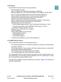
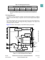
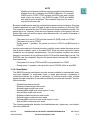
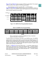
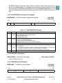
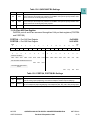
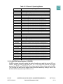
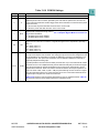
Table 13-11 QACR0 Bit Settings
Bit(s)
Name
Description
0
MUX
Externally multiplexed mode. The MUX bit configures the QADC64 for externally multiplexed
mode, which affects the interpretation of the channel numbers and forces the MA[2:0] pins to be
outputs.
0 = Internally multiplexed, 16 possible channels
1 = Externally multiplexed, 41 possible channels
1:2
—
Reserved
Trigger assignment. TRG allows the software to assign the ETRIG[2:1] pins to queue 1 and
queue 2.
0 = ETRIG1 triggers queue 1; ETRIG2 triggers queue 2
1 = ETRIG1 triggers queue 2; ETRIG2 triggers queue 1
3
TRG
4:6
—
7:11
PSH
Prescaler clock high time. The PSH field selects the QCLK high time in the prescaler. PSH value
plus 1 represents the high time in system clocks
12
PSA
Note that this bit location is maintained for software compatibility with previous versions of the
QADC64. It serves no functional benefit in the MPC555 and is not operational.
13:15
PSL
Prescaler clock low time. The PSL field selects the QCLK low time in the prescaler. PSL value
plus 1 represents the low time in system clocks
Reserved
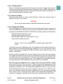
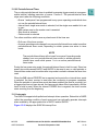
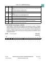
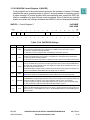
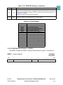
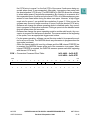
13.12.7 QADC64 Control Register 1 (QACR1)
Control register 1 is the mode control register for the operation of queue 1. The applications software defines the queue operating mode for the queue, and may enable a
completion and/or pause interrupt. All of the control register fields are read/write data.
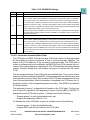
However, the SSE1 bit always reads as zero unless the test mode is enabled. Most of
the bits are typically written once when the software initializes the QADC64, and not
changed afterwards.
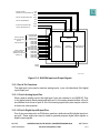
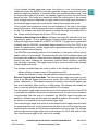
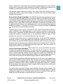
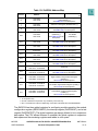
QACR1 — Control Register 1
MSB
0
1
2
CIE1
PIE1
SSE1
0
0
3
4
0x30 480C
0x30 4C0C
5
6
7
8
9
10
MQ1
11
12
13
14
LSB
15
0
0
0
RESERVED
RESET:
0
MPC555
USER’S MANUAL
0
0
0
0
0
0
0
0
0
0
QUEUED ANALOG-TO-DIGITAL CONVERTER MODULE-64
Revised 15 September 1999
MOTOROLA
13-35