1
GT16 User's Manual (Basic Utility)
SAFETY PRECAUTIONS
(Always read these precautions before using this equipment.)
Before using this product, please read this manual and the relevant manuals introduced in this manual
carefully and pay full attention to safety to handle the product correctly.
The precautions given in this manual are concerned with this product.
In this manual, the safety precautions are ranked as "WARNING" and "CAUTION".
WARNING
Indicates that incorrect handling may cause hazardous conditions, resulting in
death or severe injury.
CAUTION
CAUTION Indicates that incorrect handling may cause hazardous conditions,
resulting in minor or moderate injury or property damage.
Note that the
caution level may lead to a serious accident according to the circumstances. Always
follow the instructions of both levels because they are important to personal safety.
Please save this manual to make it accessible when required and always forward it to the end user.
[DESIGN PRECAUTIONS]
WARNING
Some failures of the GOT, communication unit or cable may keep the outputs on or off.
An external monitoring circuit should be provided to check for output signals which may lead to a
serious accident.
Not doing so can cause an accident due to false output or malfunction.
If a communication fault (including cable disconnection) occurs during monitoring on the GOT,
communication between the GOT and PLC CPU is suspended and the GOT becomes inoperative.
For bus connection: The CPU becomes faulty and the GOT becomes inoperative.
For other than bus connection: The GOT becomes inoperative.
A system where the GOT is used should be configured to perform any significant operation to the
system by using the switches of a device other than the GOT on the assumption that a GOT
communication fault will occur.
Not doing so can cause an accident due to false output or malfunction.
Do not use the GOT as the warning device that may cause a serious accident.
An independent and redundant hardware or mechanical interlock is required to configure the device
that displays and outputs serious warning.
Failure to observe this instruction may result in an accident due to incorrect output or malfunction.
A-1
[DESIGN PRECAUTIONS]
WARNING
Incorrect operation of the touch switch(s) may lead to a serious accident if the GOT backlight is gone
out.
When the GOT backlight goes out, although the POWER LED blinks (green/orange) and the display
section dims, the input of the touch switch(s) remains active.
This may confuse an operator in thinking that the GOT is in "screensaver" mode, who then tries to
release the GOT from this mode by touching the display section, which may cause a touch switch to
operate.
Note that the following occurs on the GOT when the backlight goes out.
• GT1655-V: The POWER LED blinks (green/orange) and the monitor screen appears blank.
• Models other than GT1655-V: The POWER LED blinks (green/orange) and the monitor screen
appears dimmed.
The display section of the GT16 is an analog-resistive type touch panel.
If you touch the display section simultaneously in 2 points or more, the switch that is located around
the center of the touched point, if any, may operate.
Do not touch the display section in 2 points or more simultaneously.
Doing so may cause an accident due to incorrect output or malfunction.
When programs or parameters of the controller (such as a PLC) that is monitored by the GOT are
changed,be sure to reset the GOT or shut off the power of the GOT at the same time.
Not doing so can cause an accident due to false output or malfunction.
CAUTION
Do not bundle the control and communication cables with main-circuit, power or other wiring.
Run the above cables separately from such wiring and keep them a minimum of 100mm (3.94in.)
apart.Not doing so noise can cause a malfunction.
Do not press the GOT display section with a pointed material as a pen or driver.
Doing so can result in a damage or failure of the display section.
When the GOT is connected to the Ethernet network, the available IP address is restricted according
to the system configuration.
• When multiple GOTs are connected to the Ethernet network :
Do not set the IP address (192.168.0.18) for the GOTs and the controllers in the network.
• When a single GOT is connected to the Ethernet network :
Do not set the IP address (192.168.0.18) for the controllers except the GOT in the network.
Doing so can cause the IP address duplication. The duplication can negatively affect the
communication of the device with the IP address (192.168.0.18).
The operation at the IP address duplication depends on the devices and the system.
Turn on the controllers and the network devices to be ready for communication before they
communicate with the GOT.
Failure to do so can cause a communication error on the GOT.
A-2
[MOUNTING PRECAUTIONS]
WARNING
Be sure to shut off all phases of the external power supply used by the system before mounting or
removing the GOT main unit to/from the panel.
Not doing so can cause the unit to fail or malfunction.
Be sure to shut off all phases of the external power supply used by the system before mounting or
removing the communication unit, printer unit or option function board onto/from the GOT.
Not doing so can cause the unit to fail or malfunction.
When installing the option function board, wear an earth band etc. to avoid the static electricity.
Not doing so can cause a unit corruption.
CAUTION
Use the GOT in the environment that satisfies the general specifications described in this manual.
Not doing so can cause an electric shock, fire, malfunction or product damage or deterioration.
When mounting the GOT to the control panel, tighten the mounting screws in the specified torque
range.
Undertightening can cause the GOT to drop, short circuit or malfunction.
Overtightening can cause a drop, short circuit or malfunction due to the damage of the screws or the
GOT.
When loading the communication unit or printer unit to the GOT, fit it to the extension interface of the
GOT and tighten the mounting screws in the specified torque range.
Undertightening can cause the GOT to drop, short circuit or malfunction.
Overtightening can cause a drop, failure or malfunction due to the damage of the screws or unit.
When mounting the option function board onto the GOT, connect it to the corresponding connector
securely and tighten the mounting screws within the specified torque range.
Undertightening can cause malfunction due to poor contact.
Overtightening can cause malfunction due to screw or unit damage.
When inserting a CF card into the GOT, push it into the CF card interface of GOT until the CF card
eject button will pop out.
If not properly inserted, a bad connection may cause a malfunction.
When inserting/removing a CF card into/from the GOT, turn the CF card access switch off in
advance.
Failure to do so may corrupt data within the CF card.
When removing a CF card from the GOT, make sure to support the CF card by hand, as it may pop
out.
Failure to do so may cause the CF card to drop from the GOT and break.
When installing a USB memory to the GOT, make sure to install the USB memory to the USB
interface firmly.
Failure to do so may cause a malfunction due to poor contact.
A-3
[MOUNTING PRECAUTIONS]
CAUTION
Before removing the USB memory from the GOT, operate the utility screen for removal. After the
successful completion dialog box is displayed, remove the memory by hand carefully.
Failure to do so may cause the USB memory to drop, resulting in a damage or failure of the memory.
For closing the USB environmental protection cover, fix the cover by pushing the
latch firmly to comply with the protective structure.
mark on the
Remove the protective film of the GOT.
When the user continues using the GOT with the protective film, the film may not be removed.
Operate and store the GOT in environments without direct sunlight, high temperature, dust, humidity,
and vibrations.
When using the GOT in the environment of oil or chemicals, use the protective cover for oil.
Failure to do so may cause failure or malfunction due to the oil or chemical entering into the GOT.
[WIRING PRECAUTIONS]
WARNING
Be sure to shut off all phases of the external power supply used by the system before wiring.
Failure to do so may result in an electric shock, product damage or malfunctions.
CAUTION
Always ground the FG terminal, LG terminal, and protective ground terminal of the GOT power to the
protective ground conductors dedicated to the GOT.
Not doing so may cause an electric shock or malfunction.
Terminal screws which are not to be used must be tightened always at torque 0.5 to 0.8 N·m.
Otherwise there will be a danger of short circuit against the solderless terminals.
Use applicable solderless terminals and tighten them with the specified torque.
If any solderless spade terminal is used, it may be disconnected when the terminal screw comes
loose, resulting in failure.
Correctly wire the GOT power supply section after confirming the rated voltage and terminal
arrangement of the product.
Not doing so can cause a fire or failure.
Tighten the terminal screws of the GOT power supply section in the specified torque range.
Undertightening can cause a short circuit or malfunction.
Overtightening can cause a short circuit or malfunction due to the damage of the screws or the GOT.
Exercise care to avoid foreign matter such as chips and wire offcuts entering the GOT. Not doing so
can cause a fire, failure or malfunction.
A-4
[WIRING PRECAUTIONS]
CAUTION
The module has an ingress prevention label on its top to prevent foreign matter, such as wire offcuts,
from entering the module during wiring.
Do not peel this label during wiring.
Before starting system operation, be sure to peel this label because of heat dissipation.
Plug the communication cable into the connector of the connected unit and tighten the mounting and
terminal screws in the specified torque range.
Undertightening can cause a short circuit or malfunction.
Overtightening can cause a short circuit or malfunction due to the damage of the screws or unit.
Plug the QnA/ACPU/Motion controller (A series) bus connection cable by inserting it into the
connector of the connected unit until it "clicks".
After plugging, check that it has been inserted snugly.
Not doing so can cause a malfunction due to a contact fault.
[TEST OPERATION PRECAUTIONS]
WARNING
Before performing the test operations of the user creation monitor screen (such as turning ON or
OFF bit device, changing the word device current value, changing the settings or current values of
the timer or counter, and changing the buffer memory current value), read through the manual
carefully and make yourself familiar with the operation method.
During test operation, never change the data of the devices which are used to perform significant
operation for the system.
False output or malfunction can cause an accident.
[STARTUP/MAINTENANCE PRECAUTIONS]
WARNING
When power is on, do not touch the terminals.
Doing so can cause an electric shock or malfunction.
Correctly connect the battery connector.
Do not charge, disassemble, heat, short-circuit, solder, or throw the battery into the fire.
Doing so will cause the battery to produce heat, explode, or ignite, resulting in injuly and fire.
Before starting cleaning or terminal screw retightening, always switch off the power externally in all
phases.
Not switching the power off in all phases can cause a unit failure or malfunction.
Undertightening can cause a short circuit or malfunction.
Overtightening can cause a short circuit or malfunction due to the damage of the screws or unit.
A-5
[STARTUP/MAINTENANCE PRECAUTIONS]
CAUTION
Do not disassemble or modify this unit.
Doing so can cause a failure, malfunction, injury, or fire.
Do not touch the conductive and electronic parts of the unit directly.
Doing so can cause a unit malfunction or failure.
The cables connected to the unit must be run in ducts or clamped.
Not doing so can cause the unit or cable to be damaged due to the dangling, motion or accidental
pulling of the cables or can cause a malfunction due to a cable connection fault.
When unplugging the cable connected to the unit, do not hold and pull the cable portion.
Doing so can cause the unit or cable to be damaged or can cause a malfunction due to a cable
connection fault.
Do not drop the module or subject it to strong shock.
A module damage may result.
Do not drop or give an impact to the battery mounted to the unit.
Doing so may damage the battery, causing the battery fluid to leak inside the battery.
If the battery is dropped or given an impact, dispose of it without using.
Before touching the unit, always touch grounded metal, etc. to discharge static electricity from
human body, etc.
Not doing so can cause the unit to fail or malfunction.
Before touching the unit, always touch grounded metal, etc. to discharge static electricity from
human body, etc.
Not doing so can cause the unit to fail or malfunction.
Replace battery with GT15-BAT or GT11-50BAT by Mitsubishi electric Co. only.
Use of another battery may present a risk of fire or explosion.
Dispose of used battery promptly.
Keep away from children. Do not disassemble and do not dispose of in fire.
[TOUCH PANEL PRECAUTIONS]
CAUTION
For the analog-resistive film type touch panels, normally the adjustment is not required.
However, the difference between a touched position and the object position may occur as the period
of use elapses.
When any difference between a touched position and the object position occurs, execute the touch
panel calibration.
When any difference between a touched position and the object position occurs, other object may be
activated.
This may cause an unexpected operation due to incorrect output or malfunction.
A-6
[BACKLIGHT REPLACEMENT PRECAUTIONS]
WARNING
Be sure to shut off all phases of the external power supply of the GOT (and the PLC CPU in the case
of a bus topology) and remove the GOT from the control panel before replacing the backlight (when
using the GOT with the backlight replaceable by the user).
Not doing so can cause an electric shock.
Replacing a backlight without removing the GOT from the control panel can cause the backlight to
drop, resulting in an injury.
[BACKLIGHT REPLACEMENT PRECAUTIONS]
CAUTION
Wear gloves for the backlight replacement when using the GOT with the backlight replaceable by the
user.
Not doing so can cause an injury.
Before replacing a backlight, allow 5 minutes or more after turning off the GOT when using the GOT
with the backlight replaceable by the user.
Not doing so can cause a burn from heat of the backlight.
[DISPOSAL PRECAUTIONS]
CAUTION
When disposing of this product, treat it as industrial waste.
When disposing of batteries, separate them from other wastes according to the local regulations.
(For details of the battery directive in EU member states, refer to (HardWare) Handling of Batteries
and Devices with Built-in Batteries in EU Member States.)
[TRANSPORTATION PRECAUTIONS]
CAUTION
When transporting lithium batteries, make sure to treat them based on the transport regulations.
(Refer to (HardWare) Appendix 3 for details of the regurated models.)
Make sure to transport the GOT main unit and/or relevant unit(s) in the manner they will not be
exposed to the impact exceeding the impact resistance described in the general specifications of this
manual, as they are precision devices.
Failure to do so may cause the unit to fail.
Check if the unit operates correctly after transportation.
A-7
INTRODUCTION
Thank you for choosing the Mitsubishi Graphic Operation Terminal.
Before using the equipment, please read this manual carefully to use the equipment to its optimum.
CONTENTS
SAFETY PRECAUTIONS .........................................................................................................................A - 1
INTRODUCTION ......................................................................................................................................A - 8
CONTENTS ..............................................................................................................................................A - 8
ABOUT MANUALS .................................................................................................................................A - 12
QUICK REFERENCE .............................................................................................................................A - 15
ABBREVIATIONS AND GENERIC TERMS ...........................................................................................A - 17
ABOUT DRAWING SOFTWARE VERSION...........................................................................................A - 22
HOW TO USE THIS MANUAL................................................................................................................A - 22
PACKING LIST .......................................................................................................................................A - 23
1. UTILITY FUNCTION
1.1
Utility Execution ............................................................................................................................... 1 - 1
1.2
Utility Function List........................................................................................................................... 1 - 2
1.3
Utility Display ................................................................................................................................... 1 - 6
1.3.1 Display operation of main menu ........................................................................................... 1 - 9
1.3.2 Utility basic configuration .................................................................................................... 1 - 12
1.3.3 Basic operation of settings change..................................................................................... 1 - 13
2. DISPLAY AND OPERATION SETTINGS (GOT SET UP)
2.1
GOT Main Unit Function Settings .................................................................................................... 2 - 2
2.1.1 Time setting .......................................................................................................................... 2 - 2
2.1.2 Transparent setting (Transparent mode setting) .................................................................. 2 - 6
2.1.3 Cleaning of display section (Clean) ...................................................................................... 2 - 8
2.1.4 Video/RGB setting .............................................................................................................. 2 - 10
2.1.5 Multimedia setting............................................................................................................... 2 - 18
2.1.6 License management ......................................................................................................... 2 - 35
2.1.7 Behavior of duplicate IPs .................................................................................................... 2 - 37
2.2
Display Settings ............................................................................................................................. 2 - 40
2.2.1 Display setting functions ..................................................................................................... 2 - 40
2.2.2 Display operation of display setting .................................................................................... 2 - 43
2.2.3 Display setting operations................................................................................................... 2 - 44
2.2.4 Brightness, contrast adjustment ......................................................................................... 2 - 47
2.3
Operation Settings (Settings Regarding Operation) ...................................................................... 2 - 49
2.3.1 Operation setting functions ................................................................................................. 2 - 49
2.3.2 Display operation of operation setting ................................................................................ 2 - 50
2.3.3 Setting operation of operation............................................................................................. 2 - 51
2.3.4 Security level change.......................................................................................................... 2 - 53
2.3.5 Utility call key setting .......................................................................................................... 2 - 55
2.3.6 Adjusting the touch panel position (Touch panel calibration setting).................................. 2 - 58
A-8
2.3.7
2.3.8
2.3.9
2.4
USB mouse/keyboard setting ............................................................................................. 2 - 61
SoftGOT-GOT link function setting ..................................................................................... 2 - 63
VNC(R) server function setting ........................................................................................... 2 - 66
Maintenance Function ................................................................................................................... 2 - 68
2.4.1 Maintenance time setting.................................................................................................... 2 - 68
2.4.2 Addition times reset ............................................................................................................ 2 - 70
2.4.3 GOT start time .................................................................................................................... 2 - 72
2.4.4 GOT information ................................................................................................................. 2 - 74
3. COMMUNICATION INTERFACE SETTING (COMMUNICATION SETTING)
3.1
Communication Setting.................................................................................................................... 3 - 1
3.1.1 Communication setting functions.......................................................................................... 3 - 1
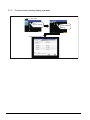
3.1.2 Communication setting display operation ............................................................................. 3 - 2
3.1.3 Communication setting contents .......................................................................................... 3 - 3
3.1.4 Communication setting operation ......................................................................................... 3 - 7
3.2
Communication Detail Setting ....................................................................................................... 3 - 13
3.2.1 Communication detail setting functions .............................................................................. 3 - 13
3.2.2 Communication detail setting display operation ................................................................. 3 - 13
3.2.3 Display contents of communication detail setting ............................................................... 3 - 16
3.3
Ethernet Setting ............................................................................................................................. 3 - 20
3.3.1 Ethernet setting function ..................................................................................................... 3 - 20
3.3.2 Display operation of Ethernet setting.................................................................................. 3 - 20
3.3.3 Display contents of Ethernet setting ................................................................................... 3 - 21
4. DEBUG
4.1
Monitor Screens............................................................................................................................... 4 - 1
4.1.1 Function of monitor screens ................................................................................................. 4 - 1
4.1.2 Display operation of monitor screens ................................................................................... 4 - 2
4.2
Debug Setting .................................................................................................................................. 4 - 3
4.2.1 Q/L/QnA ladder monitor setting ............................................................................................ 4 - 3
4.2.2 Backup/restoration setting .................................................................................................... 4 - 5
4.2.3 Trigger backup settings ........................................................................................................ 4 - 8
4.3
Memory/Data Control..................................................................................................................... 4 - 10
4.3.1 Functions of memory/data control ...................................................................................... 4 - 10
4.3.2 Backup/restoration.............................................................................................................. 4 - 12
4.3.3 GOT data package acquisition ........................................................................................... 4 - 13
4.3.4 CNC data I/O function ........................................................................................................ 4 - 16
4.3.5 Memory card format ........................................................................................................... 4 - 16
4.3.6 Memory information ............................................................................................................ 4 - 19
4.3.7 USB device status display .................................................................................................. 4 - 21
4.3.8 SRAM control ..................................................................................................................... 4 - 23
4.3.9 Motion program (SV43) I/O ................................................................................................ 4 - 27
5. SELF CHECK
5.1
Diagnostic Functions ....................................................................................................................... 5 - 1
5.1.1 Self check function ............................................................................................................... 5 - 1
5.1.2 System alarm........................................................................................................................ 5 - 2
5.1.3 Memory check ...................................................................................................................... 5 - 4
5.1.4 Drawing check ...................................................................................................................... 5 - 7
5.1.5 Font check .......................................................................................................................... 5 - 11
A-9
5.1.6
5.1.7
5.1.8
5.1.9
5.2
Touch panel check.............................................................................................................. 5 - 13
I/O check............................................................................................................................. 5 - 15
Network status display........................................................................................................ 5 - 19
Ethernet status check ......................................................................................................... 5 - 31
Batch Self Check ........................................................................................................................... 5 - 32
5.2.1 Batch self check.................................................................................................................. 5 - 32
5.2.2 Display operation of batch self check ................................................................................. 5 - 33
5.2.3 Operation of batch self check ............................................................................................. 5 - 34
6. DATA CONTROL
6.1
Data Storage Location ..................................................................................................................... 6 - 1
6.1.1 Data type and the storage location ....................................................................................... 6 - 1
6.1.2 OS version confirmation ....................................................................................................... 6 - 3
6.1.3 Capacity confirmation of the project data downloading location........................................... 6 - 4
6.1.4 Display file ............................................................................................................................ 6 - 5
6.2
Various Data Control ....................................................................................................................... 6 - 6
6.2.1 Alarm information.................................................................................................................. 6 - 6
6.2.2 Advanced recipe information .............................................................................................. 6 - 13
6.2.3 Logging information ............................................................................................................ 6 - 38
6.2.4 Operation log information ................................................................................................... 6 - 51
6.2.5 Hard copy information......................................................................................................... 6 - 68
6.2.6 Special data information ..................................................................................................... 6 - 74
6.2.7 Operator information........................................................................................................... 6 - 80
6.2.8 Fingerprint information........................................................................................................ 6 - 97
6.3
OS/Project Information ................................................................................................................ 6 - 106
6.3.1 OS information.................................................................................................................. 6 - 106
6.3.2 Project information............................................................................................................ 6 - 113
7. INSTALLATION OF COREOS, BOOTOS AND STANDARD MONITOR OS
7.1
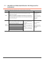
BootOS and Standard Monitor OS Required for Installation ........................................................... 7 - 2
7.2
Prior Preparations for Installing BootOS and Standard Monitor OS ................................................ 7 - 3
7.3
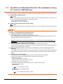
BootOS and Standard Monitor OS Installation Using CF Card or USB Memory ............................. 7 - 4
7.3.1 Installing when starting the GOT .......................................................................................... 7 - 5
7.3.2 Installing using the data control function (Utility) .................................................................. 7 - 7
7.4
When Installing the Different Version of BootOS, Standard Monitor OS ......................................... 7 - 9
7.5
CoreOS .......................................................................................................................................... 7 - 11
7.5.1 Installing the CoreOS.......................................................................................................... 7 - 11
7.5.2 When the CoreOS cannot be installed ............................................................................... 7 - 14
A - 10
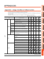
APPENDICES
Appendix1 Usage Condition of Utility Function .................................................................................... APP - 1
Appendix2 How to Choose Drive.......................................................................................................... APP - 5
Appendix3 List of Functions Added by GT Designer2 Version Upgrade (For GOT1000 Series) ......... APP - 6
INDEX
REVISIONS
WARRANTY
A - 11
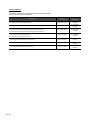
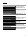
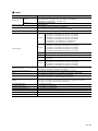
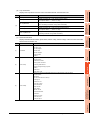
ABOUT MANUALS
The following table lists the manual relevant to GT Designer2 product.
Refer to each manual for any purpose.
Manual Name
Packaging
Manual Number
(Model code)
SH-080602ENG
GT SoftGOT1000 Version2 Operating Manual
Stored in CD-ROM
GT Designer2 Version2 Basic Operation/Data Transfer Manual (For GOT1000 Series)
Stored in CD-ROM
SH-080529ENG
(1D7M24)
GT Designer2 Version2 Screen Design Manual (For GOT1000 Series) 1/3
GT Designer2 Version2 Screen Design Manual (For GOT1000 Series) 2/3
GT Designer2 Version2 Screen Design Manual (For GOT1000 Series) 3/3
Stored in CD-ROM
SH-080530ENG
(1D7M25)
GOT1000 Series Connection Manual (1/3)
GOT1000 Series Connection Manual (2/3)
GOT1000 Series Connection Manual (3/3)
Stored in CD-ROM
SH-080532ENG
(1D7M26)
GOT1000 Series Extended/Option Functions Manual
Stored in CD-ROM
SH-080544ENG
(1D7M32)
GOT1000 Series Gateway Functions Manual
Stored in CD-ROM
SH-080545ENG
(1D7M33)
GOT1000 Series MES Interface Function Manual
Stored in CD-ROM
SH-080654ENG
(1D7M63)
A - 12
(1D7M48)
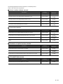
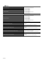
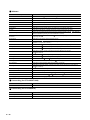
The following table lists the manual relevant to GT Works3 product.
Refer to each manual for any purpose.
Screen creation software manuals
Manual Name
Packaging
GT Works3 Version1 Installation Procedure Manual
Enclosed in product
GT Designer3 Version1 Screen Design Manual (Fundamentals) 1/2, 2/2
Stored in CD-ROM
GT Designer3 Version1 Screen Design Manual (Functions) 1/2, 2/2
Stored in CD-ROM
GT Simulator3 Version1 Operating Manual for GT Works3
Stored in CD-ROM
GT Converter2 Version3 Operating Manual for GT Works3
Stored in CD-ROM
Manual Number
(Model code)
SH-080866ENG
(1D7MB9)
SH-080867ENG
(1D7MC1)
SH-080861ENG
(1D7MB1)
SH-080862ENG
(1D7MB2)
Connection manuals
Manual Name
Packaging
Manual Number
(Model code)
GOT1000 Series Connection Manual (Mitsubishi Products) for GT Works3
Stored in CD-ROM
SH-080868ENG
(1D7MC2)
GOT1000 Series Connection Manual (Non-Mitsubishi Products 1) for GT Works3
Stored in CD-ROM
SH-080869ENG
(1D7MC3)
GOT1000 Series Connection Manual (Non-Mitsubishi Products 2) for GT Works3
Stored in CD-ROM
SH-080870ENG
(1D7MC4)
GOT1000 Series Connection Manual (Microcomputer, MODBUS Products, Peripherals) for GT
Works3
Stored in CD-ROM
SH-080871ENG
(1D7MC5)
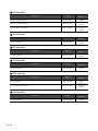
Extended and option function manuals
Manual Name
Packaging
Manual Number
(Model code)
GOT1000 Series Gateway Functions Manual for GT Works3
Stored in CD-ROM
SH-080858ENG
(1D7MA7)
GOT1000 Series MES Interface Function Manual for GT Works3
Stored in CD-ROM
SH-080859ENG
(1D7MA8)
GOT1000 Series User's Manual (Extended Functions, Option Functions) for GT Works3
Stored in CD-ROM
SH-080863ENG
(1D7MB3)
GT SoftGOT1000 manuals
Manual Name
GT SoftGOT1000 Version3 Operating Manual for GT Works3
Packaging
Stored in CD-ROM
Manual Number
(Model code)
SH-080860ENG
(1D7MA9)
A - 13
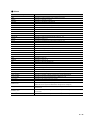
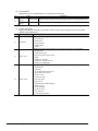
GT16 manuals
Manual Name
Packaging
Manual Number
(Model code)
GT16 User's Manual (Hardware)
Stored in CD-ROM
SH-080928ENG
(1D7MD3)
GT16 User's Manual (Basic Utility)
Stored in CD-ROM
SH-080929ENG
(1D7MD4)
GT16 Handy GOT User's Manual
Stored in CD-ROM
JY997D41201
JY997D41202
(09R821)
GT15 manuals
Manual Name
GT15 User's Manual
Packaging
Stored in CD-ROM
Manual Number
(Model code)
SH-080528ENG
(1D7M23)
GT14 manuals
Manual Name
GT14 User's Manual
Packaging
Stored in CD-ROM
Manual Number
(Model code)
JY997D44801
(09R823)
GT12 manuals
Manual Name
GT12 User's Manual
Packaging
Stored in CD-ROM
Manual Number
(Model code)
SH-080977ENG
(1D7ME1)
GT11 manuals
Manual Name
Packaging
Manual Number
(Model code)
GT11 User's Manual
Stored in CD-ROM
JY997D17501
(09R815)
GT11 Handy GOT User's Manual
Stored in CD-ROM
JY997D20101
JY997D20102
(09R817)
GT10 manuals
Manual Name
GT10 User's Manual
A - 14
Packaging
Stored in CD-ROM
Manual Number
(Model code)
JY997D24701
(09R819)
QUICK REFERENCE
Creating a project
Obtaining the specifications and operation methods of GT Designer3
Setting available functions on GT Designer3
Creating a screen displayed on the GOT
• GT Designer3 Version1 Screen Design Manual
(Fundamentals) 1/2, 2/2
• GT Designer2 Version2 Basic Operation/Data Transfer
Manual (For GOT1000 Series)
Obtaining useful functions to increase efficiency of drawing
Setting details for figures and objects
Setting functions for the data collection or trigger action
Setting functions to use peripheral devices
Simulating a created project on a personal computer
• GT Designer3 Version1 Screen Design Manual (Functions)
1/2, 2/2
• GT Designer2 Version2 Screen Design Manual (For
GOT1000 Series) 1/3, 2/3, 3/3
• GT Simulator3 Version1 Operating Manual for GT Works3
• GT Simulator2 Version2 Operating Manual
Connecting a controller to the GOT
Obtaining information of Mitsubishi products applicable to the GOT
Connecting Mitsubishi products to the GOT
Connecting multiple controllersto one GOT (Multi-channel function)
• GOT1000 Series Connection Manual (Mitsubishi Products)
for GT Works3
• GOT1000 Series Connection Manual 1/3, 2/3, 3/3
Establishing communication between a personal computer and a
controller via the GOT (FA transparent function)
Obtaining information of Non-Mitsubishi products applicable to the GOT
• GOT1000 Series Connection Manual (Non-Mitsubishi
Products 1) for GT Works3
• GOT1000 Series Connection Manual (Non-Mitsubishi
Connecting Non-Mitsubishi products to the GOT
Products 2) for GT Works3
• GOT1000 Series Connection Manual 1/3, 2/3, 3/3
Obtaining information of peripheral devices applicable to the GOT
• GOT1000 Series Connection Manual (Microcomputer,
Connecting peripheral devices including a barcode reader to the GOT
• GOT1000 Series Connection Manual 1/3, 2/3, 3/3
MODBUS Products, Peripherals) for GT Works3
Transferring data to the GOT
Writing data to the GOT
Reading data from the GOT
Verifying a editing project to a GOT project
• GT Designer3 Version1 Screen Design Manual
(Fundamentals) 1/2, 2/2
• GT Designer2 Version2 Basic Operation/Data Transfer
Manual (For GOT1000 Series)
A - 15
Others
Obtaining specifications (including part names, external dimensions, and
• GT16 User's Manual (Hardware)
options) of each GOT
• GT16 Handy GOT User's Manual
• GT15 User's Manual
• GT14 User's Manual
• GT12 User's Manual
Installing the GOT
• GT11 User's Manual
• GT11 Handy GOT User's Manual
• GT10 User's Manual
• GT16 User's Manual (Basic Utility)
• GT16 Handy GOT User's Manual
• GT15 User's Manual
Operating the utility
• GT14 User's Manual
• GT12 User's Manual
• GT11 User's Manual
• GT11 Handy GOT User's Manual
• GT10 User's Manual
• GOT1000 Series Gateway Functions Manual for GT
Configuring the gateway function
Works3
• GOT1000 Series Gateway Functions Manual
• GOT1000 Series MES Interface Function Manual for GT
Configuring the MES interface function
Works3
• GOT1000 Series MES Interface Function Manual
• GOT1000 Series User's Manual (Extended Functions,
Configuring the extended function and option function
Option Functions) for GT Works3
• GOT1000 Series Extended/Option Functions Manual
• GT SoftGOT1000 Version3 Operating Manual for GT
Using a personal computer as the GOT
Works3
• GT SoftGOT1000 Version2 Operating Manual
A - 16
ABBREVIATIONS AND GENERIC TERMS
GOT
Abbreviations and generic terms
GT1695M-X
Abbreviation of GT1695M-XTBA, GT1695M-XTBD
GT1685
GT1685M-S
Abbreviation of GT1685M-STBA, GT1685M-STBD
GT1675M-S
Abbreviation of GT1675M-STBA, GT1675M-STBD
GT1675
GT1672
GT1665
GT1675M-V
Abbreviation of GT1675M-VTBA, GT1675M-VTBD
GT1675-VN
Abbreviation of GT1675-VNBA, GT1675-VNBD
GT1672-VN
Abbreviation of GT1672-VNBA, GT1672-VNBD
GT1665M-S
Abbreviation of GT1665M-STBA, GT1665M-STBD
GT1665M-V
Abbreviation of GT1665M-VTBA, GT1665M-VTBD
GT1662
GT1662-VN
Abbreviation of GT1662-VNBA, GT1662-VNBD
GT1655
GT1655-V
Abbreviation of GT1655-VTBD
Abbreviation of GT1695, GT1685, GT1675, GT1672, GT1665, GT1662, GT1655, GT16 Handy GOT
GT16
GT1595
GT1585
GT157
GT156
GOT1000
Series
Description
GT1695
GT155
GT1595-X
Abbreviation of GT1595-XTBA, GT1595-XTBD
GT1585V-S
Abbreviation of GT1585V-STBA, GT1585V-STBD
GT1585-S
Abbreviation of GT1585-STBA, GT1585-STBD
GT1575V-S
Abbreviation of GT1575V-STBA, GT1575V-STBD
GT1575-S
Abbreviation of GT1575-STBA, GT1575-STBD
GT1575-V
Abbreviation of GT1575-VTBA, GT1575-VTBD
GT1575-VN
Abbreviation of GT1575-VNBA, GT1575-VNBD
GT1572-VN
Abbreviation of GT1572-VNBA, GT1572-VNBD
GT1565-V
Abbreviation of GT1565-VTBA, GT1565-VTBD
GT1562-VN
Abbreviation of GT1562-VNBA, GT1562-VNBD
GT1555-V
Abbreviation of GT1555-VTBD
GT1555-Q
Abbreviation of GT1555-QTBD, GT1555-QSBD
GT1550-Q
Abbreviation of GT1550-QLBD
GT15
Abbreviation of GT1595, GT1585, GT157
, GT156
GT1455-Q
Abbreviation of GT1455-QTBDE, GT1455-QTBD
GT1450-Q
Abbreviation of GT1450-QLBDE, GT1450-QLBD
GT1275
GT1275-V
Abbreviation of GT1275-VNBA, GT1275-VNBD
GT1265
GT1265-V
Abbreviation of GT1265-VNBA, GT1265-VNBD
GT145
GT14
Abbreviation of GT1455-Q, GT1450-Q
GT12
GT115
Abbreviation of GT1275, GT1265
GT1155-Q
Abbreviation of GT1155-QTBDQ, GT1155-QSBDQ, GT1155-QTBDA, GT1155-QSBDA,
GT1155-QTBD, GT1155-QSBD
GT1150-Q
Abbreviation of GT1150-QLBDQ, GT1150-QLBDA, GT1150-QLBD
GT1055-Q
Abbreviation of GT1055-QSBD
GT1050-Q
Abbreviation of GT1050-QBBD
GT1045-Q
Abbreviation of GT1045-QSBD
GT1040-Q
Abbreviation of GT1040-QBBD
GT11
GT105
GT104
, GT155
Abbreviation of GT115
, GT11 Handy GOT,
GT1030
Abbreviation of GT1030-LBD, GT1030-LBD2, GT1030-LBL, GT1030-LBDW, GT1030-LBDW2,
GT1030-LBLW, GT1030-LWD, GT1030-LWD2, GT1030-LWL, GT1030-LWDW, GT1030-LWDW2,
GT1030-LWLW, GT1030-HBD, GT1030-HBD2, GT1030-HBL, GT1030-HBDW, GT1030-HBDW2,
GT1030-HBLW, GT1030-HWD, GT1030-HWD2, GT1030-HWL, GT1030-HWDW, GT1030-HWDW2,
GT1030-HWLW
GT1020
Abbreviation of GT1020-LBD, GT1020-LBD2, GT1020-LBL, GT1020-LBDW, GT1020-LBDW2,
GT1020-LBLW, GT1020-LWD, GT1020LWD2, GT1020-LWL, GT1020-LWDW, GT1020-LWDW2,
GT1020-LWLW
GT10
Abbreviation of GT105
, GT104
, GT1030, GT1020
A - 17
Abbreviations and generic terms
GOT1000
Series
GT16
Handy
GOT
Handy
GOT
GT11
Handy
GOT
Description
GT1665HS-V
Abbreviation of GT1665HS-VTBD
GT1155HS-Q
Abbreviation of GT1155HS-QSBD
GT1150HS-Q
Abbreviation of GT1150HS-QLBD
GT SoftGOT1000
Abbreviation of GT SoftGOT1000
GOT900 Series
Abbreviation of GOT-A900 series, GOT-F900 series
GOT800 Series
Abbreviation of GOT-800 series
Communication unit
Abbreviations and generic terms
Description
Bus connection unit
GT15-QBUS, GT15-QBUS2, GT15-ABUS, GT15-ABUS2, GT15-75QBUSL, GT15-75QBUS2L,
GT15-75ABUSL, GT15-75ABUS2L
Serial communication unit
GT15-RS2-9P, GT15-RS4-9S, GT15-RS4-TE
RS-422 conversion unit
GT15-RS2T4-9P, GT15-RS2T4-25P
Ethernet communication unit
GT15-J71E71-100
MELSECNET/H communication unit
GT15-J71LP23-25, GT15-J71BR13
MELSECNET/10 communication unit
GT15-75J71LP23-Z*1, GT15-75J71BR13-Z*2
CC-Link IE Controller Network communication
unit
GT15-J71GP23-SX
CC-Link IE Field Network communication unit
GT15-J71GF13-T2
CC-Link communication unit
GT15-J61BT13, GT15-75J61BT13-Z*3
Interface converter unit
GT15-75IF900
Serial multi-drop connection unit
GT01-RS4-M
Connection Conversion Adapter
GT10-9PT5S
RS-232/485 signal conversion adapter
GT14-RS2T4-9P
*1
*2
*3
A9GT-QJ71LP23 + GT15-75IF900 set
A9GT-QJ71BR13 + GT15-75IF900 set
A8GT-J61BT13 + GT15-75IF900 set
Option unit
Abbreviations and generic terms
Printer unit
Video input unit
Video/RGB unit
Description
GT15-PRN
GT16M-V4, GT15V-75V4
RGB input unit
GT16M-R2, GT15V-75R1
Video/RGB input unit
GT16M-V4R1, GT15V-75V4R1
RGB output unit
GT16M-ROUT, GT15V-75ROUT
Multimedia unit
GT16M-MMR
CF card unit
GT15-CFCD
CF card extension unit*1
GT15-CFEX-C08SET
External I/O unit
GT15-DIO, GT15-DIOR
Sound output unit
GT15-SOUT
*1
A - 18
GT15-CFEX + GT15-CFEXIF + GT15-C08CF set.
Option
Abbreviations and generic terms
Memory card
CF card
SD card
Description
GT05-MEM-16MC, GT05-MEM-32MC, GT05-MEM-64MC, GT05-MEM-128MC,
GT05-MEM-256MC, GT05-MEM-512MC, GT05-MEM-1GC, GT05-MEM-2GC,
GT05-MEM-4GC, GT05-MEM-8GC, GT05-MEM-16GC
L1MEM-2GBSD, L1MEM-4GBSD
Memory card adaptor
GT05-MEM-ADPC
Option function board
GT16-MESB, GT15-FNB, GT15-QFNB, GT15-QFNB16M,
GT15-QFNB32M, GT15-QFNB48M, GT11-50FNB, GT15-MESB48M
Battery
GT15-BAT, GT11-50BAT
For GT16
GT16-90PSCB, GT16-90PSGB, GT16-90PSCW, GT16-90PSGW,
GT16-80PSCB, GT16-80PSGB, GT16-80PSCW, GT16-80PSGW,
GT16-70PSCB, GT16-70PSGB, GT16-70PSCW, GT16-70PSGW,
GT16-60PSCB, GT16-60PSGB, GT16-60PSCW, GT16-60PSGW,
GT16-50PSCB, GT16-50PSGB, GT16-50PSCW, GT16-50PSGW,
GT16-90PSCB-012, GT16-80PSCB-012, GT16-70PSCB-012,
GT16-60PSCB-012, GT16-50PSCB-012, GT16H-60PSC
For GT15
GT15-90PSCB, GT15-90PSGB, GT15-90PSCW, GT15-90PSGW,
GT15-80PSCB, GT15-80PSGB, GT15-80PSCW, GT15-80PSGW,
GT15-70PSCB, GT15-70PSGB, GT15-70PSCW, GT15-70PSGW,
GT15-60PSCB, GT15-60PSGB, GT15-60PSCW, GT15-60PSGW,
GT15-50PSCB, GT15-50PSGB, GT15-50PSCW, GT15-50PSGW
Protective Sheet
For GT14
GT14-50PSCB, GT14-50PSGB, GT14-50PSCW, GT14-50PSGW
For GT12
GT11-70PSCB, GT11-65PSCB
For GT11
GT11-50PSCB, GT11-50PSGB, GT11-50PSCW, GT11-50PSGW,
GT11H-50PSC
For GT10
GT10-50PSCB, GT10-50PSGB, GT10-50PSCW, GT10-50PSGW,
GT10-40PSCB, GT10-40PSGB, GT10-40PSCW, GT10-40PSGW,
GT10-30PSCB, GT10-30PSGB, GT10-30PSCW, GT10-30PSGW,
GT10-20PSCB, GT10-20PSGB, GT10-20PSCW, GT10-20PSGW
Protective cover for oil
GT05-90PCO, GT05-80PCO, GT05-70PCO, GT05-60PCO, GT05-50PCO,
GT16-50PCO, GT10-40PCO, GT10-30PCO, GT10-20PCO
USB environmental protection cover
GT16-UCOV, GT16-50UCOV, GT15-UCOV, GT14-50UCOV, GT11-50UCOV
Stand
GT15-90STAND, GT15-80STAND, GT15-70STAND, A9GT-50STAND, GT05-50STAND
Attachment
GT15-70ATT-98, GT15-70ATT-87, GT15-60ATT-97, GT15-60ATT-96,
GT15-60ATT-87, GT15-60ATT-77, GT15-50ATT-95W, GT15-50ATT-85
Backlight
GT16-90XLTT, GT16-80SLTT, GT16-70SLTT, GT16-70VLTT, GT16-70VLTTA, GT16-70VLTN,
GT16-60SLTT, GT16-60VLTT, GT16-60VLTN, GT15-90XLTT, GT15-80SLTT, GT15-70SLTT,
GT15-70VLTT, GT15-70VLTN, GT15-60VLTT, GT15-60VLTN
Multi-color display board
GT15-XHNB, GT15-VHNB
Connector conversion box
GT11H-CNB-37S, GT16H-CNB-42S
Emergency stop sw guard cover
GT11H-50ESCOV, GT16H-60ESCOV
Memory loader
GT10-LDR
Memory board
GT10-50FMB
Panel-mounted USB port extension
GT14-C10EXUSB-4S, GT10-C10EXUSB-5S
A - 19
Software
Abbreviations and generic terms
Description
GT Works3
Abbreviation of the SW
GT Designer3
Abbreviation of screen drawing software GT Designer3 for GOT1000 series
GT Simulator3
Abbreviation of screen simulator GT Simulator3 for GOT1000/GOT900 series
GT SoftGOT1000
Abbreviation of monitoring software GT SoftGOT1000
GT Converter2
Abbreviation of data conversion software GT Converter2 for GOT1000/GOT900 series
DNC-GTWK3-E and SW
DNC-GTWK3-EA
GT Designer2 Classic
Abbreviation of screen drawing software GT Designer2 Classic for GOT900 series
GT Designer2
Abbreviation of screen drawing software GT Designer2 for GOT1000/GOT900 series
iQ Works
Abbreviation of iQ Platform compatible engineering environment MELSOFT iQ Works
MELSOFT Navigator
Generic term for integrated development environment software included in the SW
Platform compatible engineering environment MELSOFT iQ Works)
GX Works2
Abbreviation of SW DNC-GXW2-E and SW
engineering software
GX Simulator2
Abbreviation of GX Works2 with the simulation function
GX Simulator
Abbreviation of SW D5C-LLT-E(-EV) type ladder logic test tool function software packages
(SW5D5C-LLT (-EV) or later versions)
GX Developer
Abbreviation of SW
D5C-GPPW-E(-EV)/SW D5F-GPPW-E type software package
GX LogViewer
Abbreviation of SW
DNN-VIEWER-E type software package
PX Developer
Abbreviation of SW
D5C-FBDQ-E type FBD software package for process control
MT Works2
DNC-IQWK (iQ
DNC-GXW2-EA type programmable controller
Abbreviation of motion controller engineering environment MELSOFT MT Works2
(SW
DNC-MTW2-E)
MT Developer
Abbreviation of SW
RNC-GSV type integrated start-up support software for motion controller Q series
MR Configurator2
Abbreviation of SW
DNC-MRC2-E type Servo Configuration Software
MR Configurator
Abbreviation of MRZJW
FR Configurator
Abbreviation of Inverter Setup Software (FR-SW
NC Configurator
Abbreviation of CNC parameter setting support tool NC Configurator
FX Configurator-FP
-SETUP
E type Servo Configuration Software
-SETUP-WE)
Abbreviation of parameter setting, monitoring, and testing software packages for FX3U-20SSC-H
(SW
D5C-FXSSC-E)
FX3U-ENET-L Configuration tool
Abbreviation of FX3U-ENET-L type Ethernet module setting software (SW1D5-FXENETL-E)
RT ToolBox2
Abbreviation of robot program creation software (3D-11C-WINE)
MX Component
Abbreviation of MX Component Version
(SW
D5C-ACT-E, SW
D5C-ACT-EA)
MX Sheet
Abbreviation of MX Sheet Version
LCPU Logging Configuration Tool
Abbreviation of LCPU Logging Configuration Tool (SW1DNN-LLUTL-E)
(SW
D5C-SHEET-E, SW
License key (for GT SoftGOT1000)
Abbreviations and generic terms
License
Description
GT15-SGTKEY-U, GT15-SGTKEY-P
License key (for GT SoftGOT2)
Abbreviations and generic terms
Description
License key
A9GTSOFT-LKEY-P (For DOS/V PC)
License key FD
SW5D5F-SGLKEY-J (For PC CPU module)
A - 20
D5C-SHEET-EA)
Others
Abbreviations and generic terms
Description
IAI
Abbreviation of IAI Corporation
AZBIL
Abbreviation of Azbil Corporation (former Yamatake Corporation)
OMRON
Abbreviation of OMRON Corporation
KEYENCE
Abbreviation of KEYENCE CORPORATION
KOYO EI
Abbreviation of KOYO ELECTRONICS INDUSTRIES CO., LTD.
SHARP
Abbreviation of Sharp Manufacturing Systems Corporation
JTEKT
Abbreviation of JTEKT Corporation
SHINKO
Abbreviation of Shinko Technos Co., Ltd.
CHINO
Abbreviation of CHINO CORPORATION
TOSHIBA
Abbreviation of TOSHIBA CORPORATION
TOSHIBA MACHINE
Abbreviation of TOSHIBA MACHINE CO., LTD.
HITACHI IES
Abbreviation of Hitachi Industrial Equipment Systems Co., Ltd.
HITACHI
Abbreviation of Hitachi, Ltd.
FUJI FA
Abbreviation of Fuji Electric FA Components & Systems Co., Ltd.
PANASONIC
Abbreviation of Panasonic Corporation
FUJI SYS
Abbreviation of Fuji Electric Systems Co., Ltd.
YASKAWA
Abbreviation of YASKAWA Electric Corporation
YOKOGAWA
Abbreviation of Yokogawa Electric Corporation
ALLEN-BRADLEY
Abbreviation of Allen-Bradley products manufactured by Rockwell Automation, Inc.
GE FANUC
Abbreviation of GE Fanuc Automation Corporation GE Fanuc Automation Corporation
LS IS
Abbreviation of LS Industrial Systems Co., Ltd.
SCHNEIDER
Abbreviation of Schneider Electric SA
SICK
Abbreviation of SICK AG
SIEMENS
Abbreviation of Siemens AG
RKC
Abbreviation of RKC INSTRUMENT INC.
HIRATA
Abbreviation of Hirata Corporation
MURATEC
Abbreviation of Muratec products manufactured by Muratec Automation Co., Ltd.
PLC
Abbreviation of programmable controller
Temperature controller
Generic term for temperature controller manufactured by each corporation
Indicating controller
Generic term for indicating controller manufactured by each corporation
Control equipment
Generic term for control equipment manufactured by each corporation
CHINO controller
Abbreviation of indicating controller manufactured by CHINO CORPORATION
PC CPU module
Abbreviation of PC CPU Unit manufactured by CONTEC CO., LTD
GOT (server)
Abbreviation of GOTs that use the server function
GOT (client)
Abbreviation of GOTs that use the client function
Windows font
Abbreviation of TrueType font and OpenType font available for Windows
(Differs from the True Type fonts settable with GT Designer3 or GT Designer2)
Intelligent function module
Indicates the modules other than the PLC CPU, power supply module and I/O module that are mounted
to the base unit
MODBUS/RTU
Generic term for the protocol designed to use MODBUS protocol messages on a serial
communication
MODBUS/TCP
Generic term for the protocol designed to use MODBUS protocol messages on a TCP/IP network
A - 21
ABOUT DRAWING SOFTWARE VERSION
This manual explains the drawing software functions of the following versions.
• GT Designer3 Version1.45X
• GT Designer2 Version2.111R or later
For GT Designer3 of a version older than the above one and GT Designer2, some functions are not supported.
Therefore, displayed screens, setting items, and others may differ from those described in the manual.
For the functions added by version upgrade of the GT Designer2, refer to the following.
GT Designer2 Version 2 Screen Design Manual
For the functions added by the version upgrade of GT Works3, contact your local distributor.
HOW TO USE THIS MANUAL
Symbols
Following symbols are used in this manual
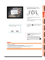
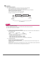
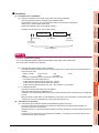
POINT
When drive is not displayed
When the drive (memory) to check is not displayed, confi rm the mounting procedure or memory type with reference
to the following.
CF Card
(Hardware) 8.5.2
Install USB peripheral devices
4.3.7 USB device status display
3
When no faults are found in mounting, etc, a memory failure may be arosen.
Replace the CF card or USB memory or built-in flash memory (C drive).
For details of built-in flash memory, contact yo ur local Mitsubishi (Electric System) Service.
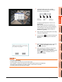
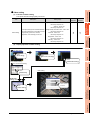
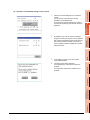
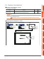
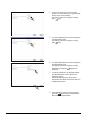
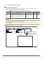
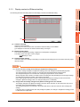
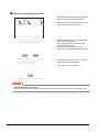
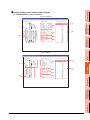
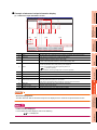
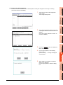
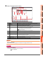
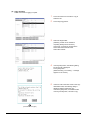
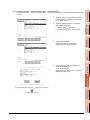
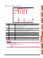
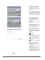
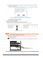
The following example explains about Memory Check using built-in flash memory (C drive).
For the Built-in CF card (A drive) memory check or Extended memory card (B drive) memory check, install the CF card
before carrying out the same key operations as built-in flash memory. For the USB drive (E drive) memory check, install
the USB memory before carrying out the check operations.
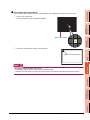
Select [Flash Memory] in the Memory check setting screen.
If select OK button, the numeric keyboard window is
displayed.
HINT
Refers to information useful
for operation.
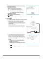
4
Show the items including detailed explanation
(Hardware)
:
GT16 User’s Manual (Hardware)
(Basic Utility)
:
GT16 User’s Manual (Basic Utility)
Shows the operation steps.
Operate the steps from the step 1.
DEBUG
1.
Refers to information
required for operation.
2
COMMUNICATION
INTERFACE SETTING
(COMMUNICATION SETTING)
(Hardware) 8.3.2
DISPLAY AND
OPERATION SETTINGS
(GOT SET UP)
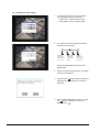
Carries out write/read check of memory.
UTILITY FUNCTION
1
Memory check operation
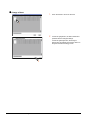
POINT
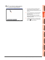
If select Cancel button, returns to the initial menu.
[
SELF CHECK
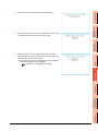
5
6
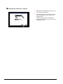
Touch to input password ( 5 9 2 0 ) and touch Enter
key.
If touch Enter key,executes read/write check for the built-in
flash memory, which is completed in around 10 seconds.
DATA CONTROL
2.
APPENDICES
INSTALLATION OF
COREOS, BOOTOS AND
STANDARD MONITOR OS
7
5.1 Diagnostic Functions
*
A - 22
5-5
The above is different from the actual page, as it is provided for explanation only.
] : Shows the setting item displayed on
the software screen or the GOT
screen.
: Refers to a button displayed on
the computer screen or the
GOT screen, or a key of the
computer keyboard.
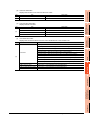
PACKING LIST
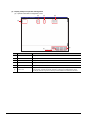
After unpacking, confirm that the following parts are included.
Model
GT1695M-X
Product
Quantity
GOT
1
Battery
1
Installation fitting
8
GT16 General Description
1
GOT
1
Battery
1
Installation fitting
4
GT16 General Description
1
GOT
1
Battery
1
Installation fitting
4
GT16 General Description
1
GT1685M-S
GT1675M-S
GT1675M-V
GT1675-VN
GT1672-VN
GT1665M-S
GT1665M-V
GT1662-VN
GT1655-V
A - 23
A - 24
1
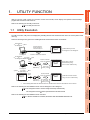
UTILITY FUNCTION
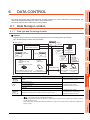
Utility is a function, which carries out connection of GOT and controller, screen display and operation method settings,
program/data control and self-check etc.
2
DISPLAY AND
OPERATION SETTINGS
(GOT SET UP)
Refer to the following for the utility function list.
1.2 Utility Function List
1.1 Utility Execution
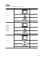
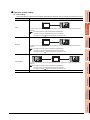
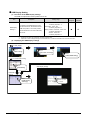
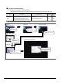
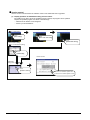
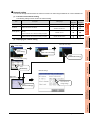
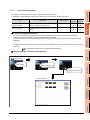
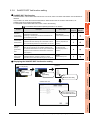
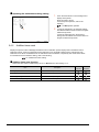
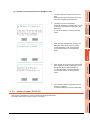
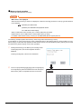
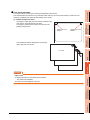
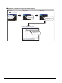
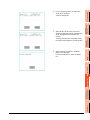
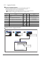
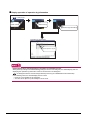
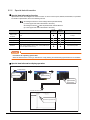
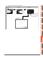
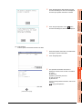
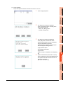
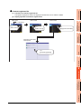
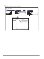
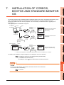
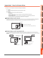
There are following three types for the installing BootOS and standard monitor OS methods.
GT Designer3
or
GT Designer2
GOT
Via USB interface or
RS-232 interface or
Ethernet interface *1
GT Designer3
or
GT Designer2
GOT
Install OS from GOT to GOT
using CF card or USB memory
GOT
BootOS or standard
monitor OS installation
CF card or
USB memory*1
CF card or
USB memory
DEBUG
CF card or
USB memory
GT Designer3
or
GT Designer2
Install the CF
card or USB
memory in GOT
5
GOT
OS file
upload
BootOS, standard
monitor OS installation
GOT
CF card or
USB memory *1
*1
When GOT is remote,
installed easily using
the CF card or USB memory
BootOS or standard OS installation
OS file
write
3) GOT
GOT
4
SELF CHECK
GT Designer3
or
GT Designer2
Installed directly from the
GT Designer3 or GT Designer2
6
DATA CONTROL
2)
GOT
3
COMMUNICATION
INTERFACE SETTING
(COMMUNICATION SETTING)
For utility execution, utility has to be displayed by installing BootOS and standard monitor OS in the C drive (built in flash
memory).
1)
UTILITY FUNCTION
1.
Install the CF
card or USB
memory in GOT
When installing the BootOS and standard monitor OS, standard monitor OS has to be installed in GOT in advance.
Refer to the following for the installation which uses GT Designer3 or GT Designer2.
7
•GT Designer2 Version
INSTALLATION OF
COREOS, BOOTOS AND
STANDARD MONITOR OS
•GT Designer3 Version1 Screen Design Manual (Fundamentals)
Basic Operation/Data Transfer Manual
Refer to the following for the installation which uses GOT.
APPENDICES
7. INSTALLATION OF COREOS, BOOTOS AND STANDARD MONITOR OS
1.1 Utility Execution
1-1
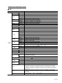
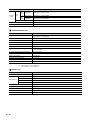
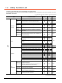
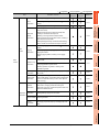
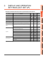
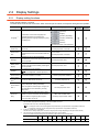
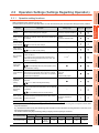
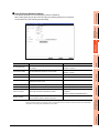
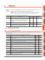
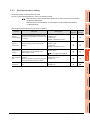
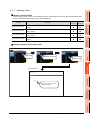
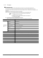
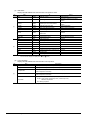
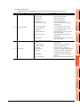
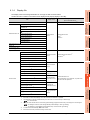
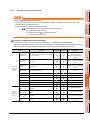
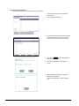
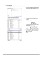
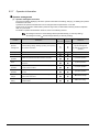
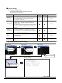
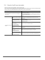
1.2 Utility Function List
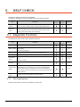
The items in the following list can be set/operated on the utility screens.
For GT Designer3 of an old version and GT Designer2, displayed screens, setting items and others may differ from those
described in the manual.
(
Item
GOT main
unit setup
: Supported
Functions overview
Time setting
Displaying and setting the clock current time
Transparent
Setting the channel No. to be used for the
mode
communication for the FA transparent function
Clean
Displaying the screen for cleaning the display
Video/RGB
Displaying the screen for setting the video/RGB I/O
setting
unit
Multimedia
setting
Displaying the screen for setting the multimedia
License
Displaying the screen for registering and releasing
management
the license
Behavior of
duplicate IPs
: Partly supported
: Not supported)
For GT
For GT
Designer2
Designer3
Reference
2.1.1
2.1.2
2.1.3
2.1.4
2.1.5
2.1.6
Setting the GOT operation when a device with the
same IP address as that of the GOT is added to the
2.1.7
network afterwards.
Switching message languages
Setting the startup screen display time and screen
saving time
Setting the backlight to ON or OFF during screen
Display
2.2
saving
Setting the battery alarm display to ON or OFF
Setting the detect level/detect time of human sensor
GOT
Adjusting brightness and contrast
setup
2.2.4
Setting the buzzer volume and window move buzzer
Setting the key sensitivity and key reaction speed
2.3
Setting the touch detection mode
Operation
Changing security levels
2.3.4
Setting the utility call keys
2.3.5
Adjusting the touch panel
2.3.6
Setting the USB mouse/keyboard
2.3.7
Setting the SoftGOT-GOT link function
2.3.8
Setting the VNC server function
2.3.9
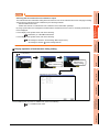
Setting the maintenance notification times for the
Maintenance
backlight and display
timing setting
Setting the number of maintenance notifications for
2.4.1
touch keys and the built-in flash memory
GOT
Addition
Resetting accumulated hours and counts for
maintenance
times reset
maintenance time notifications
GOT start
Displaying the GOT start date and time, current time,
time
and accumulated operating hours
GOT
information
Displaying the GOT information
2.4.2
2.4.3
2.4.4
(Continued to next page)
1-2
1.2 Utility Function List
Functions overview
: Partly supported
For GT
For GT
Designer2
Designer3
Assigning channel numbers and communication
(When connecting to FX series CPU)
Starting the system monitor
Ladder monitor
Starting the ladder monitor
monitor
Intelligent
module monitor
Servo amplifier
monitor
Debug
Starting the CNC monitor
FX list editor
Starting the FX list editor
A list editor
Starting the A list editor
SFC monitor
Starting the SFC monitor
Ladder edit
Starting the ladder edit
monitor
Log viewer
Monitor
Motion program
screens2
(SV43) editor
setting
Starting the servo amplifier monitor
CNC monitor
Motion SFC
Debug
Starting the intelligent module monitor
Starting the motion monitor
troubleshooting
3
Starting the network monitor
Motion monitor
MELSEC-L
3.3
the host
System monitor
Network
screens1
Displaying the contents of Ethernet setting, changing
2
COMMUNICATION
INTERFACE SETTING
(COMMUNICATION SETTING)
Ethernet setting
Monitor
3.2
canceling sequence program protection status
4
4.1
DEBUG
setting
5
Starting the MELSEC-L troubleshooting
SELF CHECK
setting
deleting sequence program protection key words,
Starting the motion SFC monitor
Starting the log viewer
6
Starting the motion program (SV43) editor
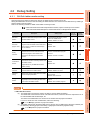
Q/L/QnA ladder
Setting the data storage location for the MELSEC-Q/
monitor
L/QnA ladder monitor function
4.2.1
Setting the storage locations for backup data and
Backup/
backup settings, setting the maximum number of
restoration
backup data, and setting whether to specify the
setting
backup CPU No. or not
4.2.2
Setting the trigger backup
4.2.3
(Continued to next page)
DATA CONTROL
nication
Setting communication parameters, setting or
cation setting
7
INSTALLATION OF
COREOS, BOOTOS AND
STANDARD MONITOR OS
nication
Communi-
1
APPENDICES
Commu-
Reference
3.1
drivers to communication interfaces
Commu-
: Not supported)
UTILITY FUNCTION
Item
: Supported
DISPLAY AND
OPERATION SETTINGS
(GOT SET UP)
(
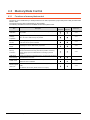
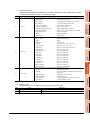
1.2 Utility Function List
1-3
(
Item
Functions overview
Backup/
restoration
GOT data
package
acquisition
CNC data I/O
function
Memory card
Debug
: Supported
Memory/
format
data
Memory
control
information
USB device
status display
Executing the backup/restoration function
Copying the OS, special data, and project data to a
CF card or USB memory
: Partly supported
: Not supported)
For GT
For GT
Designer2
Designer3
Reference
4.3.2
4.3.3
Starting the CNC data I/O function
4.3.4
Formatting a CF card or USB memory
4.3.5
Displaying the available memory of the GOT
4.3.6
Displaying the status of USB device
4.3.7
Confirming the SRAM user area usage, backing up
SRAM control
or restoring the data in the SRAM user area, and
4.3.8
initializing the SRAM user area
Motion
program
Starting the motion program (SV43) I/O
4.3.9
Displaying the system alarm
5.1.2
(SV43) I/O
System alarm
Memory check
Self
check
Write/read check of the CF card or USB memory and
built-in flash memory.
5.1.3
Drawing check
Checking the drawing
5.1.4
Font check
Checking the font
5.1.5
Checking the touch panel
5.1.6
Checking the I/O of RS-232 interface
5.1.7
Displaying the network status
5.1.8
Checking the connection status of Ethernet
5.1.9
Diagnostic
Touch panel
functions
check
I/O check
Network status
display
Ethernet status
check
Batch self check
Executing various diagnostics collectively and
copying the result to a CF card or USB memory
5.2
(Continued to next page)
1-4
1.2 Utility Function List
: Not supported)
For GT
For GT
Designer2
Designer3
Reference
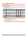
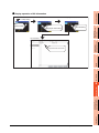
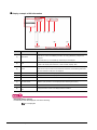
Deleting or copying alarm log files
Alarm
Converting alarm log files in G1A format
information
format
CSV/TXT
6.2.1
2
Displaying graphs of alarm log files
Converting advanced recipe files in GIP format
CSV/TXT format,
Deleting/copying/moving advanced recipe files,
Advanced
creating a new advanced recipe file
Recipe
Deleting or moving advanced recipe folders,
information
changing advanced recipe folder names, creating a
6.2.2
3
new advanced recipe folder
Writing/reading/matching record data and deleting
device values with the advanced recipe record list
Converting logging files in G1L format
Data
control
1
UTILITY FUNCTION
Functions overview
: Partly supported
CSV/TXT
format
Logging
Deleting/copying/moving logging files, changing
information
logging file names
DISPLAY AND
OPERATION SETTINGS
(GOT SET UP)
Item
: Supported
6.2.3
COMMUNICATION
INTERFACE SETTING
(COMMUNICATION SETTING)
(
4
Deleting logging folders, creating a new logging
folder
Converting operation log files in G1O format
CSV/
Deleting/copying/moving operation log files,
information
changing operation log file names
6.2.4
Deleting operation log folders, creating a new
5
operation log folder
Hard copy
Deleting/copying hard copy files, changing hard copy
information
file names
6.2.5
Deleting or checking special data files, deleting
Special data
special data folders, downloading special data stored
information
in the CF card/USB memory to the C drive (Built-in
6.2.6
flash memory)
6
Adding/editing/deleting/importing/exporting operator
Operator
information, changing passwords, setting the
information
automatic logout time, password expiration date and
6.2.7
external authentication ID
information
Fingerprint
information
OS information
Project
Information
Adding/deleting fingerprint information
6.2.8
Installing or uploading OS, displaying OS property,
checking OS data
6.3.1
Downloading/uploading/deleting/copying project files,
displaying project file property, checking project file
6.3.2
data
7
APPENDICES
OS/project
SELF CHECK
Operation log
DATA CONTROL
control
INSTALLATION OF
COREOS, BOOTOS AND
STANDARD MONITOR OS
Data
DEBUG
TXT format
1.2 Utility Function List
1-5
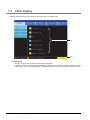
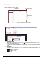
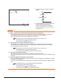
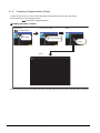
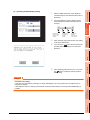
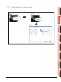
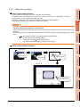
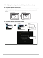
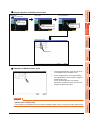
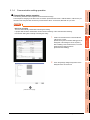
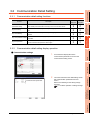
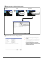
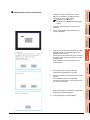
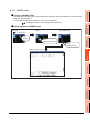
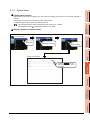
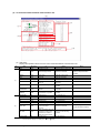
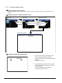
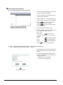
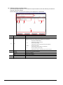
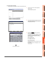
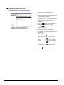
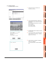
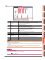
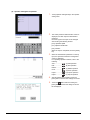
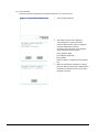
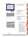
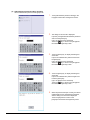
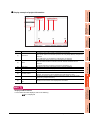
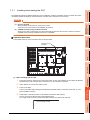
1.3 Utility Display
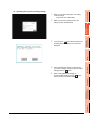
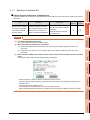
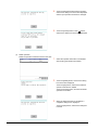
To display setting screens fot each utility, the main menu has to be displayed first.
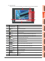
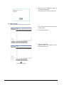
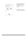
(1)
(2)
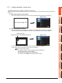
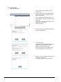
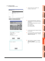
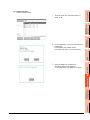
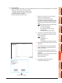
(1) Main menu
The menu items that can be set at the GOT utility are displayed.
Touching a menu item in the main menu will display the setting screen or following selection screen for the item.
In this manual, with a few special exceptions, explanations are given primarily using the GT1685M-S screens.
1-6
1.3 Utility Display
1
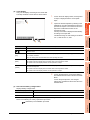
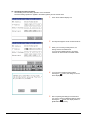
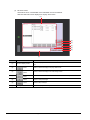
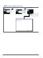
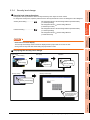
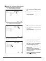
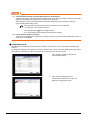
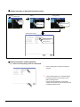
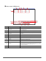
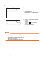
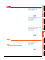
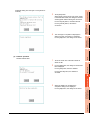
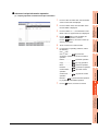
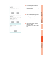
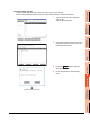
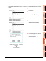
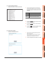
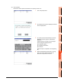
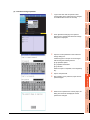
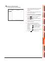
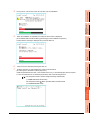
(2) System message switch button
UTILITY FUNCTION
This button switches the language used for the utility or system alarms.
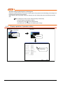
When touching the Language button, the Select Language screen is displayed.
DISPLAY AND
OPERATION SETTINGS
(GOT SET UP)
2
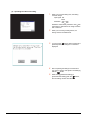
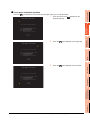
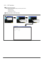
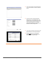
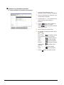
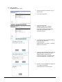
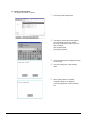
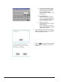
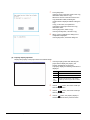
2.
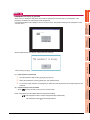
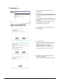
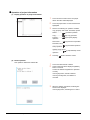
Touch the button of the language to be displayed.
Touching the [OK] button restarts the GOT and the language on the utility is switched to the selected one.
If touch the [Cancel] button, the changed settings are canceled and the screen returns to the Main Menu.
4
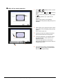
POINT
When starting the GOT without selecting any language or the selected language and the installed fonts are
not matched
The following screen will be displayed.
Touching the button of a desired language restarts the GOT and the language is switched to the selected one.
DEBUG
1.
COMMUNICATION
INTERFACE SETTING
(COMMUNICATION SETTING)
3
SELF CHECK
5
DATA CONTROL
6
APPENDICES
INSTALLATION OF
COREOS, BOOTOS AND
STANDARD MONITOR OS
7
1.3 Utility Display
1-7
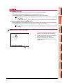
HINT
(1) Selectable languages
The system message switch button is displayed only for the selectable languages.
The selectable languages differ depending on the fonts installed in the GOT.
For the relation between the selectable languages and the fonts, refer to the following.
GT Designer3 Version1 Screen Design Manual (Fundamentals) (2.5 Specifications of Applicable
Characters)
GT Designer2 Version
Screen Design Manual (2.3 Specifications of Applicable Characters)
(2) System language switching using the device
The system language can be switched using the system language switching device set with GT Designer3.
For the setting method of the system language switching device, refer to the following.
GT Designer3 Version1 Screen Design Manual (Fundamentals) (4.3 Language Switching Device
Setting)
1-8
1.3 Utility Display
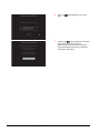
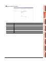
1
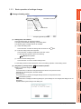
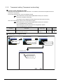
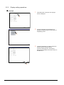
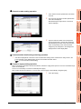
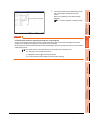
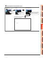
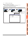
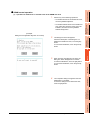
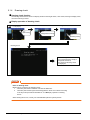
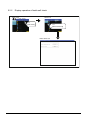
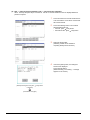
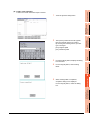
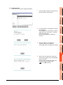
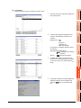
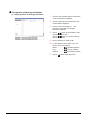
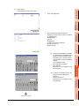
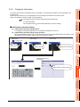
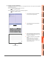
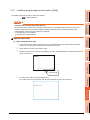
Display operation of main menu
UTILITY FUNCTION
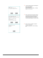
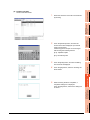
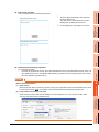
1.3.1
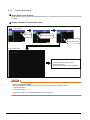
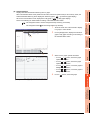
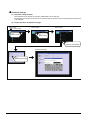
The following three types of operation can display the main menu.
(Display the main menu after installing the basic OS from GT Designer3 or GT Designer2 to the GOT built in flash
memory.)
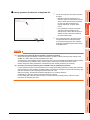
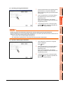
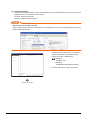
(1) When project data is undownloaded
If the power supply of GOT turns ON, the main menu is displayed automatically after title display.
2
DISPLAY AND
OPERATION SETTINGS
(GOT SET UP)
Main menu
GOT power supply ON
COMMUNICATION
INTERFACE SETTING
(COMMUNICATION SETTING)
3
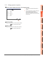
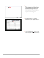
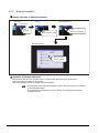
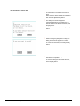
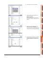
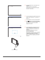
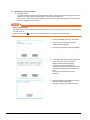
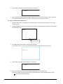
(2) When touching menu call key
If you touch the menu call key while user-created screen is displayed, the main menu is displayed.
The menu call key is set in the position on the GOT screen upper left corner at factory shipment.
4
Main menu
DEBUG
Menu call key
1-point touch on the upper-left corner
5
SELF CHECK
The menu call key can be set by the GOT utility, GT Designer3 or GT Designer2.
For the setting method of the utility call key, refer to the following.
•2.3.5 Utility call key setting
•GT Designer3 Version1 Screen Design Manual (Fundamentals)
(4.9 GOT Display and Operation Setting)
•GT Designer2 Version Screen Design Manual
(3.8 Setting of GOT Display and Operations (GOT Setup))
DATA CONTROL
6
APPENDICES
INSTALLATION OF
COREOS, BOOTOS AND
STANDARD MONITOR OS
7
1.3 Utility Display
1-9
POINT
(1) Prohibited simultaneous 2-point presses
Do not touch 2 points or more on the GOT screen simultaneously. Touching 2 points or more simultaneously
may activate a part other than the touched point.
(2) When setting menu call key to 1-point
When having set [Pressing time] of the menu call key setting screen to other than "0 (s)", keep pressing the
touch panel for the period set to [Pressing time] or more before leaving the finger from the touch panel.
For menu call key setting, refer to the following.
2.3.5 Utility call key setting
(3) When touching special function switch (utility)
If you touch the special function switch (utility) while user-created screen is displayed, the main menu is
displayed.
The special function switch (utility) can be set as a touch switch that is displayed on a user-created screen by
GT Designer3 or GT Designer2.
Main menu
Special function switch
(Utility)
For the details of the special function switch, refer to the following.
•GT Designer3 Version1 Screen Design Manual (Functions)
(2.6 Setting Special Function Switch)
•GT Designer2 Version
Screen Design Manual
(6.2.5 Setting items of special function switch)
1 - 10
1.3 Utility Display
HINT
2
DISPLAY AND
OPERATION SETTINGS
(GOT SET UP)
Locking the utility display by password
When you try to display the utility main menu while the password is set to the GOT by GT Designer3 or GT
Designer2, the display for password input will be appeared.
(The password setting of GT Designer3 is in the common menu. The password setting of GT Designer2 is in the
common menu.)
UTILITY FUNCTION
1
COMMUNICATION
INTERFACE SETTING
(COMMUNICATION SETTING)
3
4
DEBUG
When the password is not matched, displays the error message.
SELF CHECK
5
When touching the [OK] button, the screen returns to the monitor screen.
1.
Input the password after touching [0] to [9], [A] to [F] key.
2.
Define the password by touching [Enter] key, after password input.
3.
To correct the input character, touch [Del] key to delete the correcting character and reinput/retype the new
character.
7
(2) Password input cancel operation
button is touched, it returns to the monitor screen.
INSTALLATION OF
COREOS, BOOTOS AND
STANDARD MONITOR OS
When
Refer to the following for the details related to the password setting.
•GT Designer3 Version1 Screen Design Manual (Fundamentals)
Screen Design Manual
APPENDICES
•GT Designer2 Version
DATA CONTROL
6
(1) Input operation of password
1.3 Utility Display
1 - 11
1.3.2
Utility basic configuration
The basic configuration of utility is as follows.
Title display
Close/Return button
Scroll button
Screen
(1) Title display
The screen title name is displayed in title display part.
As the screen is composed of multiple layers, the title including these layers is displayed.
Title display
Title display
(2) Close/Return button
When a middle screen of the layers is displayed, if the
(Close/return) button in the right corner of screen is
touched, returns to the previous screen.
If this button is touched when directly displayed from monitor screen, the screen is closed and returns to monitor
screen.
(3) Scroll button
For screens in which the content does not fit on one screen page, there is a right or down scroll button on the
screen.
1 - 12
/
/
/
Scroll one line/column
/
/
/
Scroll window
1.3 Utility Display
1
Basic operation of settings change
UTILITY FUNCTION
1.3.3
Change of setting value
Close/Return button
DISPLAY AND
OPERATION SETTINGS
(GOT SET UP)
2
Select button
Setting item
COMMUNICATION
INTERFACE SETTING
(COMMUNICATION SETTING)
3
Example: [Operation] screen
(1) Setting item, select button
Touch the select button to change the settings.
The setting methods differ depending on the setting items.
The following types of setting method are available.
4
(a) Switch the setting value.
Touch the button to switch the setting value as shown in ON
OFF .
DEBUG
(b) Enter the setting value with a keyboard.
Touch the button to display a keyboard on the GOT screen.
For the keyboard operation, refer to the following.
5
Keyboard operation
SELF CHECK
Move to another setting screen.
Touch the button to move to another setting screen.
For the setting method of each setting item, refer to the setting operation of each setting screen.
(Close/Return) button
Reflect or cancel the changed settings.
• [OK] button
Touch this button to reflect the changed settings and return to the previous screen.
Depending on the setting item, the GOT restarts.
• [Cancel] button
Touch this button to cancel the changed settings and return to the previous screen.
(Close/Return) button
Touch this button to display the following dialog box. (If the settings are not changed, the dialog box is not
displayed.)
Operate following the message of the dialog box.
7
APPENDICES
•
6
DATA CONTROL
(2) [OK] button, [Cancel] button,
INSTALLATION OF
COREOS, BOOTOS AND
STANDARD MONITOR OS
(c)
1.3 Utility Display
1 - 13
Keyboard operation
1. Touch the numerical value to be changed.
2.
Keyboard for numerical input is displayed and cursor is displayed simultaneously.
The key board display position chanegs by the position of numerical value touched.
(At the time of numerical input, displayed in the position which will not interrupt the inputting.)
Cursor
Keyboard
3.
Input numeric with keyboard.
• [0] to [9] Key: Input the numeric.
• [Enter] Key: Complete numeric input and close the keyboard.
• [Cancel] Key: Cancel numeric input and close the keyboard.
•
/
Key: Moves the cursor to the right or left side.
Available only if any selectable item is at the right/left side of the cursor.
• [Del] Key: Cancel the input by 1 character.
• [*] key and the key which is not mentioned do not function.
4.
1 - 14
If [Enter] key is touched, numeric input is completed and keyboard is closed.
1.3 Utility Display
1
DISPLAY AND OPERATION
SETTINGS (GOT SET UP)
UTILITY FUNCTION
2.
2
Clock setting, clock display, GOT internal battery voltage status
2.1.1
Transparent mode
Ch No.
2.1.2
Clean
Cleaning the display section
2.1.3
3
Video/RGB Setting
Video unit, video display, RGB display
2.1.4
Multimedia setting
Multimedia equipment, video display, long time recording setting
2.1.5
License management
Registering/releasing the license
2.1.6
Item
Setting the GOT operation when a device with the same IP
address as that of the GOT is added to the network afterwards.
For GT
For GT
Designer2
Designer3
Reference
2.1.7
4
Language, opening screen time, screen save time, screen save
backlight, battery alarm display, sensor detect level, sensor detect
Security setting
2.3.4
5
Utility call key
2.3.5
Touch panel calibration
2.3.6
USB mouse/keyboard setting
2.3.7
SoftGOT-GOT link function setting
2.3.8
VNCserver function setting
2.3.9
Maintenance timing setting
2.4.1
Addition times reset
2.4.2
GOT start time
2.4.3
GOT information
2.4.4
6
7
INSTALLATION OF
COREOS, BOOTOS AND
STANDARD MONITOR OS
reaction speed, Touch detection mode
SELF CHECK
2.3.1
Buzzer volume, window move buzzer volume, Key sensitivity, Key
GOT maintenance
2.2.4
DEBUG
Adjusting the brightness and contrast
Operation
2.2.1
time
APPENDICES
Display
DATA CONTROL
Behavior of duplicate IPs
Description
COMMUNICATION
INTERFACE SETTING
(COMMUNICATION SETTING)
Time setting
DISPLAY AND
OPERATION SETTINGS
(GOT SET UP)
Setting screen for display and setting screen for operation can be displayed from the GOT utility screen.
In the setting screen for display and the setting screen for operation, the following settings can be set.
2-1
2.1 GOT Main Unit Function Settings
2.1.1
Time setting
Time setting functions
Time setting and displaying of the status of GOT built-in battery are possible.
Item
Description
For GT
For GT
Designer2
Designer3
Setup the method to adjust the time between GOT clock data
Time setting
(1) Time setting
and clock data of controller connected to the GOT.
Clock display
Carry out the display and setup of GOT clock data.
GOT internal battery
voltage status
Reference
(2) Clock display
(3) GOT internal
Displays GOT internal battery voltage status.
battery voltage
status
POINT
Changing times
When the time is changed on the Time setting & display screen, the changed time is written in a programmable
controller even though [Adjust] or [Broadcast] is set for [Time setting].
As a result, the time of the programmable controller can be changed on the GOT even though [Adjust] is set for
[Time setting].
(The clock data of the controller set as [Adjust CH No.] of [Clock data GOT is matched to clock data External
(Adjust)] in [GOT Setup] ([Clock Setting]) of GT Designer3 or in [System Environment] ([Time setting]) of GT
Designer2 is changed.)
For details of [Adjust] and [Broadcast], refer to the following manual.
•GT Designer3 Version1 Screen Design Manual (Fundamentals)
•GT Designer2 Version
Screen Design Manual
Display operation of time setting
Main menu
(
Time setting
1.3 Utility Display)
Touch
[Time setting]
2-2
2.1 GOT Main Unit Function Settings
Set the Time setting
and Clock setting
(1) Time setting
Setup the method to adjust the time between GOT data and the clock data of controller connected to the GOT.
Setting
Description
Adjust the time of GOT clock data to the clock data of controller.
UTILITY FUNCTION
1
Operation of time setting
It is same as set in the GOT setup in Environmental Setting of GT Designer3 or in System Environment of GT
Designer2.
•GT Designer3 Version1 Screen Design Manual (Fundamentals)
4.9.2 How to match clock data between the GOT and controllers
•GT Designer2 Version
3
Screen Design Manual 2.5 Clock Function
Adjust the time of controller clock data to the clock data of GOT.
Broadcast
It is same as set in the GOT setup in Environmental Setting of GT Designer3 or in System Environment of GT
Designer2.
4
•GT Designer3 Version1 Screen Design Manual (Fundamentals)
4.9.2 How to match clock data between the GOT and controllers
•GT Designer2 Version
COMMUNICATION
INTERFACE SETTING
(COMMUNICATION SETTING)
Adjust
DISPLAY AND
OPERATION SETTINGS
(GOT SET UP)
2
Screen Design Manual 2.5 Clock Function
DEBUG
Adjust the GOT and controllers to the controller whose clock data is used as a base.
Adjust/Broadcast
It is same as set in the GOT setup in Environmental Setting of GT Designer3 or in System Environment of GT
Designer2.
5
•GT Designer3 Version1 Screen Design Manual (Fundamentals)
Screen Design Manual 2.5 Clock Function
No adjustment of clock data.
DATA CONTROL
6
INSTALLATION OF
COREOS, BOOTOS AND
STANDARD MONITOR OS
7
APPENDICES
None
SELF CHECK
4.9.2 How to match clock data between the GOT and controllers
•GT Designer2 Version
2.1 GOT Main Unit Function Settings
2-3
1.
If touch the setup item, the setup contents is
changed.
Adjust
Broadcast
Adjust/Broadcast
None
2.
If touch the [OK] button, the GOT restarts and
operates with the changed settings.
If touch the [Cancel] button, the changed
settings are canceled and the screen returns
to the Main Menu.
POINT
(1) When connecting to an external device which does not have clock function
If set to [Adjust] or [Broadcast] for clock setting while the GOT is connected to external devices (PLC or
microcomputers) which do not have clock function, the clock data will not be adjusted.
Refer to the following for the list of PLC installed with clock function.
•GOT1000 Series Connection Manual for GT Works3 and a controller used
•GT Designer2 Version
Screen Design Manual
(2.5.3 PLC CPUs with clock function)
(2) Clock setting when using the multi-channel function
The channel No. of a controller whose clock is used as a base or adjusted cannot be set by the utility.
The controller whose clock is used as a base or adjusted can be set by GT Designer3 or GT Designer2.
For channel settings, refer to the following.
•GOT1000 Series Connection Manual for GT Works3 and a controller used
•GT Designer2 Version
Screen Design Manual
(2.5.1 Synchronizing clock data between GOT and PLC CPU)
(3) Setting of clock setting and battery
The connector of the GOT is not connected to the battery connector at purchase.
When selecting [Broadcast] or [None] in clock setting, set the clock of the GOT once with connecting a battery
to the GOT.
(4) Operation setting by GT Designer3 or GT Designer2
Carry out the setting of clock setting in [GOT set up] in [Environmental Setting] of GT Designer3 or in [System
Environment] of GT Designer2.
To change a part of the setting after downloading the project data, change the setting at the display setting of
GOT.
•GT Designer3 Version1 Screen Design Manual (Fundamentals)
(4.9 GOT Display and Operation Setting)
•GT Designer2 Version
Screen Design Manual
(3.8 Setting of GOT Display and Operation (GOT Setup))
2-4
2.1 GOT Main Unit Function Settings
2.
Key
If touch the clock display section, the keyboard
for input is displayed and the clock update
stops.
Input time with the keyboard by referring to the
table below. Input the scheduled time when the
operation of step3 is to be carried out since the
input time is reflected at the time of the
operation of step3.
The day of the week is displayed automatically
according to the input date.
The effective range of clock setting is as follows.
Jan. 1, 2000 to Dec. 31, 2037
Description
[0] to [9]
2
DISPLAY AND
OPERATION SETTINGS
(GOT SET UP)
1.
3
COMMUNICATION
INTERFACE SETTING
(COMMUNICATION SETTING)
Carry out the display and seting of GOT clock data.
The setup methods of clock data are shown below.
UTILITY FUNCTION
1
(2) Clock display
4
Input numeric value in cursor position.
Move the cursor.
/
Move the cursor to the left by one character when [Del] Key is touched while inputting year, month, day,
[Del]
time, minutes, seconds.
DEBUG
Carry out nothing when touched other than when inputting the above.
Close the keyboard after the input time is displayed in clock display.
[Enter]
5
The update of the clock display does not restart even if the keyboard is closed.
The update of the clock display restarts with the operation of step3.
Cancel the input time and returns the time of clock display to the time at which the keyboard was displayed
SELF CHECK
and close the keyboard.
The update of the clock display does not restart even if the keyboard is closed.
The update of the clock display restarts with the operation of step3.
3.
If touch the [OK] button, the changed settings
are reflected and the screen returns to the Main
Menu.
If touch the [Cancel] button, the changed
settings are canceled and the screen returns to
the Main Menu.
(3) GOT internal battery voltage status
6
DATA CONTROL
[Cancel]
7
Display
Status
Normal
Normal
Low/None
Low voltage
INSTALLATION OF
COREOS, BOOTOS AND
STANDARD MONITOR OS
Displays battery voltage status.
When the battery voltage is low, replace the battery immediately.
Refer to the following for battery replacement procedure.
APPENDICES
(Hardware) 8.3.2 Installation procedure
2.1 GOT Main Unit Function Settings
2-5
2.1.2
Transparent setting (Transparent mode setting)
Function of the transparent mode
When using the multi-channel function, the channel No. of a controller to which the FA transparent function is
executed can be specified.
For the multi-channel function, refer to the following manual.
•GOT1000 Series Connection Manual (Mitsubishi Products) for GT Works3
(20 MULTI-CHANNEL FUNCTION)
•GT Designer2 Version
Screen Design Manual (2.8 Multi-channel Function)
Also, refer to the following manual for the FA transparent function.
•GOT1000 Series Connection Manual (Mitsubishi Products) for GT Works3
(21 FA TRANSPARENT FUNCTION)
•GOT1000 Series Connection Manual for GT Designer2/GT Works2
(53 FA TRANSPARENT FUNCTION)
Functionf
ChNo.
Description
Setting range
The channel No. of a controller to which the FA transparent
1/2/3/4
function is executed can be set.
<Default: 1>
For GT
For GT
Designer2
Designer3
Displaying the transparent mode
Main menu
(
GOT main unit setup
Transparent Mode Setting
1.3 Utility Display)
Touch
Touch
[GOT setup]
[GOT main unit setup]
Touch
[Transparent made]
Transparent mode
Touch the channel No.
display area of ChNo.
2-6
2.1 GOT Main Unit Function Settings
1
2.
Touching the transparent ChNo. (numerical
part) on the left, the keyboard is displayed.
Input numerical value by the keyboard.
If touch the [OK] button, the GOT restarts and
operates with the changed settings.
If touch the [Cancel] button, the changed
settings are canceled and the screen returns to
the Main Menu.
2
DISPLAY AND
OPERATION SETTINGS
(GOT SET UP)
1.
UTILITY FUNCTION
Operation the transparent mode
COMMUNICATION
INTERFACE SETTING
(COMMUNICATION SETTING)
3
DEBUG
4
SELF CHECK
5
DATA CONTROL
6
APPENDICES
INSTALLATION OF
COREOS, BOOTOS AND
STANDARD MONITOR OS
7
2.1 GOT Main Unit Function Settings
2-7
2.1.3
Cleaning of display section (Clean)
In utility, the screen can be set as not to be effected by touching the screen when clean with clothes.
Refer to the below for the cleaning procedure.
(Hardware) 9.3 Cleaning Method
Display operation of Clean
Main menu
(
GOT main unit setup
Clean
1.3 Utility Display)
Touch
Touch
[GOT setup]
[GOT main unit setup]
Touch
[Clean]
Clean
Even if touch points other than the upper left corner and upper right corner of the screen, the GOT does not operates.
2-8
2.1 GOT Main Unit Function Settings
1
UTILITY FUNCTION
Operation of Clean
After cleaning the screen, touch the screen following the instruction displayed.
After touching the screen, the screen returns to the Main Menu.
The following screen is displayed.
DISPLAY AND
OPERATION SETTINGS
(GOT SET UP)
2
COMMUNICATION
INTERFACE SETTING
(COMMUNICATION SETTING)
3
DEBUG
4
SELF CHECK
5
DATA CONTROL
6
APPENDICES
INSTALLATION OF
COREOS, BOOTOS AND
STANDARD MONITOR OS
7
2.1 GOT Main Unit Function Settings
2-9
2.1.4
Video/RGB setting
Video unit setting
(1) Functions of the video unit settings
The video input signal and resolution can be selected.
Item
Description
Setting range
For GT
For GT
Designer2
Designer3
Input signal: NTSC format, PAL format
<At factory shipment: NTSC format>
Video Unit
The input signal and resolution can be selected.
Settings*1
Resolution: 640
720
480,
480*2, 768
<At factory shipment : 640
*1
*2
576*2
480>
GT1675-VN, GT1672-VN, GT1662-VN, GT1655-V cannot be used.
Can be selected only in PAL format
For GT1675M-V or GT1665M-V, the resolution is 640
480.
POINT
Input signal settings
Set the input signal as follows according to the output format for the video camera or the like connected.
If the settings made differ from these, video images may not be displayed correctly.
Output format for video camera or the like
2 - 10
Input signal setting
NTSC format
NTSC
PAL format
PAL
EIA format
NTSC
CCIR format
PAL
2.1 GOT Main Unit Function Settings
1
Main Menu
GOT setup
GOT main unit setup
1.3 Utility Display)
Touch
[GOT setup]
2
Touch
[GOT main unit setup]
DISPLAY AND
OPERATION SETTINGS
(GOT SET UP)
(
UTILITY FUNCTION
(2) Displaying the video unit setting
Touch
[Video/RGB Setting]
Communication setting
(
3.1 Communication Setting)
[Video/RGB]
COMMUNICATION
INTERFACE SETTING
(COMMUNICATION SETTING)
3
Touch
Video Unit Settings
Video/RGB
setting
4
DEBUG
Touch an item to be set
SELF CHECK
5
DATA CONTROL
6
7
INSTALLATION OF
COREOS, BOOTOS AND
STANDARD MONITOR OS
[Video Unit Settings]
APPENDICES
Touch
2.1 GOT Main Unit Function Settings
2 - 11
(3) Operating the video unit setting
1.
2.
3.
4.
2 - 12
2.1 GOT Main Unit Function Settings
When you touch the setting item, the setting
contents change.
Input signal :PAL
NTSC
Resolution :720 480
768 576
640 480
When you touch the [Confirm] button, the
setting contents are determined.
If you touch the
button without touching
the [Confirm] button, the dialog box on the left
is displayed.
After completing the settings for all the items
you want to change in [Video Unit Settings],
when closing [Video Unit Settings] and [Video/
RGB Setting]/[Communication Setting] with
the
button, the GOT is restarted, and the
new setting contents are reflected.
(1) Functions of the video display settings
The target for the video settings and the preview channel can be selected and the captive area and image
quality can be set.
Item
Description
Setting range
For GT
For GT
Designer2
Designer3
<At factory shipment : 1>
preview channel can be selected and the
captive area
(in the horizontal direction and vertical
Video Display
direction) and image quality (color tone,
Settings*1
contrast, brightness, color intensity) can be
set.
The captive area and image quality can be
set for each channel.
Captive area Horizontal: -100 to 100
<At factory shipment: 0>
Vertical: -100 to 100
<At factory shipment: 0>
Image Quality and Color Tone: -100 to 100
3
<At factory shipment: 0>
COMMUNICATION
INTERFACE SETTING
(COMMUNICATION SETTING)
The target for the video settings and the
Contrast: -100 to 100
<At factory shipment: 0>
Brightness: -100 to 100
<At factory shipment: 0>
Intensity: -100 to 100
<At factory shipment: 0>
*1
2
DISPLAY AND
OPERATION SETTINGS
(GOT SET UP)
Channel 1/2/3/4
UTILITY FUNCTION
1
Video Display Setting
4
GT1675-VN, GT1672-VN, GT1662-VN, GT1655-V cannot be used.
(2) Displaying the video display setting
(
GOT setup
GOT main unit setup
DEBUG
Main Menu
1.3 Utility Display)
5
Touch
[GOT setup]
Touch
[GOT main unit setup]
[Video/RGB Setting]
Communication Setting
(
3.1 Communication Setting)
SELF CHECK
Touch
6
[Video/RGB]
Video Display Setting
DATA CONTROL
Touch
Video/RGB
Setting Menu
[Video Display
Settings]
Touch an item
to be set
APPENDICES
Touch
INSTALLATION OF
COREOS, BOOTOS AND
STANDARD MONITOR OS
7
2.1 GOT Main Unit Function Settings
2 - 13
(3) Operating the video display setting
1.
2.
3.
Select a video channel No. to be displayed.
The video image for the selected channel No. is
previewed.
To change the captive area or image quality,
touch the display section of each item.
Captive Area : Refer to step3 to step6.
Image Quality : Refer to step7 to step10.
The captive area (horizontal direction/vertical
direction) for the selected channel No. can be
changed.
Moves the
captive area a
certain distance
in the direction.
Moves the
captive area
to the touched
position.
Moves the
captive area a
certain distance
in the direction.
Touching the [Default] button returns to the
default status.
4.
5.
6.
2 - 14
2.1 GOT Main Unit Function Settings
When touching the [Confirm] button, the setting
contents are determined.
If you touch the
button without touching the
[Confirm] button, the dialog box on the left is
displayed.
After completing all the items to set, if you touch
the
button, the display returns to the
preview screen step1.
7.
UTILITY FUNCTION
1
The image quality (color tone, contrast,
brightness, color intensity) for the selected
channel No. can be changed.
Changes the
number to the
touched
position.
Changes the
number a
certain amount
in the direction.
Touching the [Default] button returns to the
default status.
When touching the [Copy CH1] button, the
image quality (color tone, contrast, brightness,
color intensity) for the selected channel No. is
matched with the image quality settings for
Channel No. 1 ([CH1]).
8.
4
If you touch the
button without touching the
[Confirm] button, the dialog box on the left is
displayed.
DEBUG
9.
When touching the [Confirm] button, the setting
contents are determined.
3
COMMUNICATION
INTERFACE SETTING
(COMMUNICATION SETTING)
Changes the
number a
certain amount
in the direction.
DISPLAY AND
OPERATION SETTINGS
(GOT SET UP)
2
the
button, the display returns to the
preview screen step1.
11. After completing the settings for all the items
6
DATA CONTROL
you want to change in the video display
settings, when closing [Video Display (Preview)]
with the
button, the display returns to
[Video/RGB Setting].
SELF CHECK
10.After completing all the items to set, if you touch
5
POINT
7
APPENDICES
INSTALLATION OF
COREOS, BOOTOS AND
STANDARD MONITOR OS
Precautions for setting
Incorrect settings may disrupt or stop the video image.
(If this happens, returning the settings to their default values restores normal display.)
This phenomenon depends on the video camera or other device connected.
Use setting values that provide proper display.
2.1 GOT Main Unit Function Settings
2 - 15
RGB Display Setting
(1) Functions of the RGB display settings
The RGB clock phase and screen position can be set.
Item
Description
Setting range
For GT
For GT
Designer2
Designer3
Channel 1/2
The target for the RGB settings and the
preview channel can be selected and the
RGB Display
RGB clock phase *2 and screen position
Settings *1
(horizontal direction and vertical direction)
<At factory shipment : 1>
ClockPhase: -100 to 100
<At factory shipment: 0>
Display position Horizontal: -100 to 100
can be set.
<At factory shipment: 0>
Vertical: -100 to 100
<At factory shipment: 0>
*1
*2
GT1675-VN, GT1672-VN, GT1662-VN, GT1655-V cannot be used.
Adjust when a noise is displayed along the horizontal direction or characters are blotted or the contours are unclear.
(2) Displaying the RGB display settings
Main Menu
(
GOT setup
GOT main unit setup
1.3 Utility Display)
Touch
Touch
[GOT setup]
[GOT main unit setup]
Touch
[Video/RGB setting]
Communication setting
(
3.1 Communication Setting)
Touch
[Video/RGB]
RGB Display settings
Video/RGB
Settings
Touch
[RGB Display
Settings]
2 - 16
2.1 GOT Main Unit Function Settings
Touch an item
to be set
The clock phase and screen display position
(horizontal direction/vertical direction) can be
changed.
Changes the
number a certain
amount in the
direction.
3.
Changes the
number a
certain amount
in the direction.
3
When touching the [Confirm] button, the setting
contents are determined.
If you touch the
button without touching the
[Confirm] button, the dialog box on the left is
displayed.
4
DEBUG
4.
Changes the
number to the
touched
position.
2
DISPLAY AND
OPERATION SETTINGS
(GOT SET UP)
2.
Select an RGB channel No. to be displayed.
The RGB image for the selected channel No. is
previewed.
COMMUNICATION
INTERFACE SETTING
(COMMUNICATION SETTING)
1.
UTILITY FUNCTION
1
(3) Operating the RGB display setting
After completing all the items to set, if you touch
the
button, the display returns to [Video/
RGB Setting].
POINT
7
APPENDICES
INSTALLATION OF
COREOS, BOOTOS AND
STANDARD MONITOR OS
Precautions for setting
If the value for [Horizontal] or [Vertical] is too large, RGB display may not be performed or the display may be
disrupted or stopped.
If this happens, return the settings to their default values and make settings in the range where RGB display is
possible.
6
DATA CONTROL
5.
SELF CHECK
5
2.1 GOT Main Unit Function Settings
2 - 17
2.1.5
Multimedia setting
Video Unit Settings
(1) Functions of the video unit settings
The video input signal and resolution can be selected.
Item
Description
Setting range
For GT
For GT
Designer2
Designer3
Input signal: NTSC format, PAL format
Video Unit
Settings
*1
The input signal and resolution can be
<At factory shipment: NTSC>
selected.
Resolution: 640 480*2, 768 576*3
<At factory shipment : 640 480>
*1 GT1675-VN, GT1672-VN, GT1662-VN, GT1655-V cannot be used.
*2 When NTSC format is selected, the resolution is fixed to 640
*3 When PAL format is selected, the resolution is fixed to 768
480.
576.
POINT
Input signal settings
Set the input signal as follows according to the output format for the video camera or the like connected.
If the settings made differ from these, video images may not be displayed correctly.
Output format for video camera or the like
2 - 18
Input signal setting
NTSC format
NTSC
PAL format
PAL
EIA format
NTSC
CCIR format
PAL
2.1 GOT Main Unit Function Settings
1
Main Menu
GOT main unit setup
GOT setup
1.3 Utility Display)
Touch
[GOT setup]
2
Touch
[GOT main unit setup]
DISPLAY AND
OPERATION SETTINGS
(GOT SET UP)
(
UTILITY FUNCTION
(2) Displaying the video unit setting
Touch
[Multimedia setting]
Communication setting
(
3.1 Communication Setting)
3
COMMUNICATION
INTERFACE SETTING
(COMMUNICATION SETTING)
Touch
Video Unit Settings
[Multimedia]
Multimedia
setting menu
4
Touch an item
to be set
Touch
DEBUG
[Video Unit Settings]
SELF CHECK
5
DATA CONTROL
6
APPENDICES
INSTALLATION OF
COREOS, BOOTOS AND
STANDARD MONITOR OS
7
2.1 GOT Main Unit Function Settings
2 - 19
(3) Operating the video unit setting
1.
2.
3.
4.
5.
2 - 20
2.1 GOT Main Unit Function Settings
When you touch the setting item, the setting
contents change.
Input signal :PAL
NTSC
Resolution :720 480
640 480
Resolution automatically switches to 640 480
when NTSC is selected and to 768 576 when
PAL is selected.
When you touch the [Confirm] button, the
setting contents are determined.
If you touch the
button without touching the
[Confirm] button, the dialog box on the left is
displayed.
After completing the settings for all the items
you want to change, close [Video Unit Settings]
with the
button.
When closing [Multimedia Setting] or
[Communication Setting] with the
button,
the new setting contents are reflected.
(1) Function of Video setting
The captive area and image quality can be set.
Item
Description
Setting range
For GT
For GT
Designer2
Designer3
2
Captive area Horizontal: -100 to 100
DISPLAY AND
OPERATION SETTINGS
(GOT SET UP)
<At factory shipment: 0>
Vertical: -100 to 100
<At factory shipment: 0>
The captive area (in the horizontal direction
and vertical direction) for the video and the
Video setting
image quality (color tone, contrast,
Image Quality and Color Tone: -100 to 100
<At factory shipment: 0>
Contrast: -100 to 100
brightness, color intensity) can be set.
<At factory shipment: 0>
3
COMMUNICATION
INTERFACE SETTING
(COMMUNICATION SETTING)
Brightness: -100 to 100
<At factory shipment: 0>
Intensity: -100 to 100
<At factory shipment: 0>
(2) Display operation of Video setting
Main Menu
GOT setup
4
GOT main unit setup
1.3 Utility Display)
Touch
[GOT setup]
Touch
[GOT main unit setup]
DEBUG
(
Touch
5
[Multimedia setting]
Communication setting
3.1 Communication Setting)
Touch
SELF CHECK
(
UTILITY FUNCTION
1
Video setting
Video setting
[Multimedia]
6
Touch
DATA CONTROL
Multimedia
setting menu
Touch an item
to be set
7
APPENDICES
INSTALLATION OF
COREOS, BOOTOS AND
STANDARD MONITOR OS
[Video setting]
2.1 GOT Main Unit Function Settings
2 - 21
(3) Operation of Video setting
1.
2.
To change the captive area or image quality,
touch the display section of each item.
Captive Area : Refer to step2 to step5
Image Quality : Refer to step6 to step9.
The captive area (horizontal direction/vertical
direction) can be changed.
Moves the
captive area a
certain distance
in the direction.
Moves the
captive area
to the touched
position.
Moves the
captive area a
certain distance
in the direction.
Touching the [Default] button returns to the
default status.
3.
4.
5.
2 - 22
2.1 GOT Main Unit Function Settings
When touching the [Confirm] button, the setting
contents are determined.
If you touch the
button without touching the
[Confirm] button, the dialog box on the left is
displayed.
After completing all the items to set, if you touch
the
button, the display returns to the
preview screen
.
6.
UTILITY FUNCTION
1
The image quality (color tone, contrast,
brightness, color intensity) for the selected
channel No. can be changed.
Changes the
number to the
touched
position.
Changes the
number a
certain amount
in the direction.
Touching the [Default] button returns to the
default status.
When touching the [Confirm] button, the setting
contents are determined.
If you touch the
button without touching the
[Confirm] button, the dialog box on the left is
displayed.
4
DEBUG
7.
3
COMMUNICATION
INTERFACE SETTING
(COMMUNICATION SETTING)
Changes the
number a
certain amount
in the direction.
DISPLAY AND
OPERATION SETTINGS
(GOT SET UP)
2
9.
After completing all the items to set, if you touch
the
button, the display returns to the
preview screen step1.
After completing the settings for all the items
you want to change in [Video setting], when
closing [Video setting (preview)] with the
button, the display returns to [Multimedia setting
menu].
POINT
6
DATA CONTROL
8.
SELF CHECK
5
7
APPENDICES
INSTALLATION OF
COREOS, BOOTOS AND
STANDARD MONITOR OS
Precautions for setting
Incorrect settings may disrupt or stop the video image.
(If this happens, returning the settings to their default values restores normal display.)
This phenomenon depends on the video camera or other device connected.
Use setting values that provide proper display.
2.1 GOT Main Unit Function Settings
2 - 23
Long time recording setting
(1) Functions of long time recording settings
In the long time recording settings, the saving method of video files for long time recording can be set.
Item
Description
Setting range
For GT
For GT
Designer2
Designer3
At the long time recording, whether to start
Continuous
recording after deleting all the video files
Valid/Invalid
save
which are previously recorded or to start
<At factory shipment: Invalid>
recording without the deletion can be set.
(2) Displaying the long time recording settings
GOT setup
Main Menu
(
GOT main unit setup
1.3 Utility Display)
Touch
[GOT setup]
Touch
[GOT main unit setup]
Touch
[Multimedia setting]
Communication setting
(
3.1 Communication Setting)
Touch
Long time recording settings
[Multimedia]
Multimedia
setting menu
Touch
[Long time
recording settings]
2 - 24
2.1 GOT Main Unit Function Settings
Set the saving method
of the file for the long
time recording.
1.
When you touch the [Confirm] button, the
setting contents are determined.
2
DISPLAY AND
OPERATION SETTINGS
(GOT SET UP)
2.
When you touch the setting item, the setting
contents change.
Continuous save: Valid/Invalid
UTILITY FUNCTION
1
(3) Operating the long time recording settings
3.
If you touch the
button without touching the
[Confirm] button, the dialog box on the left is
displayed.
COMMUNICATION
INTERFACE SETTING
(COMMUNICATION SETTING)
3
DEBUG
4
4.
When closing [Multimedia Setting] or
[Communication Setting] with the
button,
the new setting contents are reflected.
6
DATA CONTROL
5.
After completing the settings for all the items
you want to change, close [Long time recording
settings] with the
button.
SELF CHECK
5
APPENDICES
INSTALLATION OF
COREOS, BOOTOS AND
STANDARD MONITOR OS
7
2.1 GOT Main Unit Function Settings
2 - 25
Version control
Version control is executed when the software version of the multimedia unit is upgraded.
(1) Display operation of multimedia setting version control
By installing a CF card in which the updated program is stored, the program can be updated.
Prepare the updated program from either of the followings.
• CD-ROM of GT Works3 or GT Designer2
• Contact your local distributor.
Main Menu
(
GOT setup
GOT main unit setup
1.3 Utility Display)
Touch
[GOT setup]
Touch
[GOT main unit setup]
Touch
[Multimedia setting]
Communication setting
(
3.1 Communication Setting)
Touch
[Multimedia]
Version control
Multimedia
setting menu
Touch
[Version control]
Touch the unit software update menu
to switch to the software update screen.
2 - 26
2.1 GOT Main Unit Function Settings
2.
By installing a CF card in which the updated
program is stored, the program can be updated.
Only when the updated program newer than the
unit software version is stored, the version of
newer updated program is displayed in Update
software version.
2
DISPLAY AND
OPERATION SETTINGS
(GOT SET UP)
Check the version displayed in Unit software
version.
It is the version of the software currently
installed in the multimedia unit.
Touch the [Unit software Update menu] button,
and then the update program transfer screen is
displayed.
3
COMMUNICATION
INTERFACE SETTING
(COMMUNICATION SETTING)
1.
UTILITY FUNCTION
1
(2) Operation of multimedia setting version control
4.
To update the program to the new version,
touch [Update] button
The dialog shown left is displayed.
Touch [OK] button, and then the software is
updated.
Touch [Cancel], and then the software is not
updated.
5
SELF CHECK
3.
DEBUG
4
DATA CONTROL
6
APPENDICES
INSTALLATION OF
COREOS, BOOTOS AND
STANDARD MONITOR OS
7
2.1 GOT Main Unit Function Settings
2 - 27
5.
6.
7.
2 - 28
2.1 GOT Main Unit Function Settings
The dialog box shown left is displayed during
the update of update program.
Do not pull out the CF card or power OFF the
GOT while the dialog box shown left is
displayed.
Do not turn off the CF card access switch of the
multimedia unit.
The software is not updated properly.
When the update of update program is
completed normally, the dialog box shown left is
displayed.
When the update program is not correct or the
update of update program failed, the dialog box
shown left is displayed.
After restarting the GOT, apply the steps starting
from step1 again.
The network setting is executed when the network connection is made using the Ethernet I/F of the multimedia unit.
(1) Functions of the network setting
The following settings can be made in the network setting.
Description
Setting range
Displays the MAC address.
IP address
Displays and sets the IP address.
0.0.0.0 to 255.255.255.255
<Default: 192.168.3.51>
Default gateway
Displays and sets the router address of the default
gateway.
For the connection via a router, the setting is required.
0.0.0.0 to 255.255.255.255
<Default: 0.0.0.0>
Subnet mask
Displays and sets the subnet mask.
For the connection via a router, the setting is required.
0.0.0.0 to 255.255.255.255
<Default: 255.255.255.0>
For GT
Designer3
-
3
(2) Displaying the network setting
GOT setup
Main Menu
(
2
DISPLAY AND
OPERATION SETTINGS
(GOT SET UP)
MAC address
For GT
Designer2
COMMUNICATION
INTERFACE SETTING
(COMMUNICATION SETTING)
Item
UTILITY FUNCTION
1
Network setting
GOT main unit setup
1.3 Utility Display)
4
Touch
[GOT setup]
Touch
[GOT main unit setup]
Communication setting
(
3.1 Communication Setting)
DEBUG
Touch
[Multimedia setting]
5
SELF CHECK
Touch
[Multimedia]
Network settings
6
DATA CONTROL
Multimedia
setting menu
Touch an item to
change settings
Touch
[Network settings]
APPENDICES
INSTALLATION OF
COREOS, BOOTOS AND
STANDARD MONITOR OS
7
2.1 GOT Main Unit Function Settings
2 - 29
(3) Operating the network setting
The following shows the setting operation of the IP address.
The same setting operation is applied to the default gateway and the subnet mask.
1.
Touch the IP address display box.
2.
The keyboard appears. Enter numerical values.
3.
4.
5.
2 - 30
2.1 GOT Main Unit Function Settings
When you touch the [Confirm] button, the
setting contents are determined.
If you touch the [Default] button, the setting
contents can be returned to the initial values.
If you touch the [Confirm] button without
touching the
button, the dialog box on the
left is displayed.
After completing the settings for all the items
you want to change in [Network settings], when
touching the
button, the display returns to
[Multimedia setting menu].
Multimedia screen
(1) Display operation of multimedia screen
2
DISPLAY AND
OPERATION SETTINGS
(GOT SET UP)
Create the multimedia screen switch used to display the multimedia screen on the project screen.
Touch the multimedia screen switch so that the screen is switched to the multimedia screen.
The video image, play video and file selection menu can be switched on the multimedia screen.
For details of the procedures for creating the extended function switch used to display the multimedia screen,
refer to the following manual.
UTILITY FUNCTION
1
•GT Designer3 Version1 Screen Design Manual (Functions)
(2.6 Setting Special Function Switch)
•GT Designer2 Version Screen Design Manual
(6.2.5 Setting items of special function switch)
Play video position display function
For using the video playing position display function on the play video screen, the software version 03.00.00 or
later of the multimedia unit is required.
If the software version of the multimedia unit is old, an error message is displayed.
For how to upgrade the multimedia software, refer to the following.
4
DEBUG
Version control
COMMUNICATION
INTERFACE SETTING
(COMMUNICATION SETTING)
3
POINT
SELF CHECK
5
DATA CONTROL
6
APPENDICES
INSTALLATION OF
COREOS, BOOTOS AND
STANDARD MONITOR OS
7
2.1 GOT Main Unit Function Settings
2 - 31
(2) Operation of multimedia screen
(a) Video image screen
Images taken with a video camera connected to the multimedia unit can be displayed on the GOT screen.
Images taken with a video camera can be recorded.
(1)
(2)
(3)
(4)
(5)
(6)
(7)
(8)
(9)
(10)
(11)
(12)
Number
(1)
Image display screen
Description
Screen to display images taken with a video camera
(2)
button
Button to pause images taken with a video camera
(3)
button
Button to start recording images taken with a video camera
(4)
button
Button to stop recording
(5)
button
Button to start printing the screen
(6)
button
Button to cancel printing the screen
(7)
button
Button to switch the display to the play video screen
(8)
button
Button to switch the screen to the file menu screen
(9)
button
Button to exit the multimedia screen switch and to return to the utility screen
(10)
button
Button to accept messages
(11)
button
Button to stop messages
(12)
2 - 32
Item
Message display screen
Screen to display error messages, etc.
2.1 GOT Main Unit Function Settings
1
(1)
UTILITY FUNCTION
(b) Play video screen
Video files saved in the CF card installed on the multimedia unit can be played and displayed.
(2) (3)
(4)
(5)
(6)
(7)
DISPLAY AND
OPERATION SETTINGS
(GOT SET UP)
2
(8)
(9)
(10)
(11)
3
COMMUNICATION
INTERFACE SETTING
(COMMUNICATION SETTING)
(12)
(13)
(14)
(16)
(15)
Item
Screen to display images taken with a video camera or to play video taken with a video
(1)
Image display screen
(2)
button
Play button for playing video
(3)
button
Button to pause images or video taken with a video camera
button
(6)
button
Button to return to the beginning of video files and to play the video
(7)
button
Button to play the video in slow motion
(8)
button
Button to start printing the screen
(9)
button
Button to cancel printing the screen
(10)
button
Button to switch the display to the video image screen
(11)
button
Button to switch the display to the video image screen
(12)
button
Button to exit the multimedia screen switch and to return to the utility screen
(13)
button
Button to accept messages
(14)
button
Button to stop messages
(15)
Message display screen
(16)
Play position display bar
*1
DEBUG
Button to return to the beginning of video files and to play the video
SELF CHECK
(5)
5
Button to stop playing
6
DATA CONTROL
button
camera
7
INSTALLATION OF
COREOS, BOOTOS AND
STANDARD MONITOR OS
(4)
4
Description
Screen to display the file name and shooting time of the video being played and
messages*1
APPENDICES
Number
Bar to display the play position of the video
This screen displays the shooting time of a video file saved with the GOT (unit software version 03.02.00 or later only).
2.1 GOT Main Unit Function Settings
2 - 33
(c)
File menu screen
Video files of the CF card installed on the multimedia unit can be searched.
Searched video files can be displayed on the play video screen.
(1)
(2)
(3)
(4)
(5)
(6)
(7)
Number
(1)
File menu display screen
Description
Screen to display video files in the CF card selected by Select drive or to delete video
files.
(2)
button
Button to switch the display to the play video screen
(3)
button
Button to switch the display to the video image screen
(4)
button
Button to exit the multimedia screen switch and to return to the utility screen
(5)
button
Button to accept messages
(6)
button
Button to stop messages
(7)
2 - 34
Item
Message display screen
Screen to display error messages, etc.
2.1 GOT Main Unit Function Settings
For using functions which require a license, register the license for the GOT.
For releasing a registered license for the GOT, also execute on the license management screen.
Description
Setting range
PC Remote Operation
Registers and deletes the license of the PC
function (Ethernet)
Remote Operation function (Ethernet).
VNC server function
For GT
For GT
Designer2
Designer3
-
Registers/deletes the license of the VNC server
-
function.
2
DISPLAY AND
OPERATION SETTINGS
(GOT SET UP)
Item
UTILITY FUNCTION
1
License management
License management function
For the remote personal computer operation function (Ethernet) and the VNCserver function, the license
registration and the cancellation of the license registration are available.
The GT1675-VN, GT1672-VN, and GT1662-VN do not support the remote personal computer operation function
(Ethernet).
For details of the remote personal computer operation function (Ethernet) and the VNCserver function, refer to the
following.
3
COMMUNICATION
INTERFACE SETTING
(COMMUNICATION SETTING)
2.1.6
4
GT Designer3 Version1 Screen Design Manual (Functions)
Display operation of license management
GOT setup
DEBUG
GOT main unit setup
1.3 Utility Display)
[GOT main unit setup]
Touch
[License management]
6
License management
DATA CONTROL
[GOT setup]
5
Touch
7
INSTALLATION OF
COREOS, BOOTOS AND
STANDARD MONITOR OS
Touch
APPENDICES
(
SELF CHECK
Main Menu
2.1 GOT Main Unit Function Settings
2 - 35
Setting operation of license management
(1) When registering a license number for the GOT
1.
2.
3.
Touch the license number input area on the
license management screen, and then the
keyboard appears on the bottom of the
screen.
Touch the [Regist] button to register the
input license number.
If the
button is touched without touching
the [Regist] button, the license number is not
registered.
After a license number is registered, touch
the
button to close the license
management screen.
(2) When releasing a license number for the GOT
1.
2.
Touch the [Cancel reg.] button to release the
registered license number.
Touch the
button to close the license
management screen.
POINT
How to acquire a license number
For how to acquire a license number, please consult your local Mitsubishi (Electric System) Service center or
representative.
2 - 36
2.1 GOT Main Unit Function Settings
Setting function for Behavior of duplicate IPs
The GOT operation can be set when a device with the same IP address as that of the GOT is added to the network
afterwards.
Description
Setting range
Behavior when a device
of the same IP address
as the GOT’s address
joins the network
The GOT operation can be set
when a device with the same IP
address as that of the GOT is
added to the network afterwards.
Maintain a network connection
(rec)/Do not maintain a network
connection
<Default: Maintain a network
connection (rec)>
For GT
For GT
Designer2
Designer3
2
DISPLAY AND
OPERATION SETTINGS
(GOT SET UP)
Items
UTILITY FUNCTION
1
Behavior of duplicate IPs
3
COMMUNICATION
INTERFACE SETTING
(COMMUNICATION SETTING)
POINT
(1) For checking IP address duplication
Use CoreOS with the version 05.10.00AG or later.
(2) When the IP address duplication is not checked
(a) When the IP address of the GOT is set to 192.168.0.18, the IP address duplication check is not
performed.
(3) When the GOT is added to the network in which a device with the same IP address as that of the GOT
exists
GOT goes into offline status and the following dialog box appears.
DEBUG
4
(b) Depending on the device to connect with the GOT, the IP address duplication check may not be
performed.
SELF CHECK
5
6
7
APPENDICES
INSTALLATION OF
COREOS, BOOTOS AND
STANDARD MONITOR OS
• When correcting the same IP address of other device as that of GOT
After correcting the same IP address of other device as that of GOT, touch the [Reboot GOT] button to
restart the GOT.
• When changing the IP address of GOT
Touch the [Clear IP Address] button to clear the IP address of GOT.
After touching the [Reboot GOT] button to restart the GOT, change the IP address of GOT by the utility.
DATA CONTROL
2.1.7
2.1 GOT Main Unit Function Settings
2 - 37
Display operation of Behavior of duplicate IPs
Main Menu
(
GOT setup
GOT main unit setup
1.3 Utility Display)
Touch
[GOT setup]
Touch
[GOT main unit setup]
Touch
[Behavior of duplicate
IPs]
Behavior of duplicate IPs
2 - 38
2.1 GOT Main Unit Function Settings
2.
If touch the [OK] button, the GOT restarts
and operates with the changed settings.
If touch the [Cancel] button, the changed
settings are canceled and the screen returns
to the Main Menu.
2
DISPLAY AND
OPERATION SETTINGS
(GOT SET UP)
If touch the setup item, the setup contents is
changed.
• Maintain a network connection (rec):
The GOT stays connected to the network
when a device with the same IP address
as that of the GOT is added to the
network afterwards. A system alarm
occurs.
• Do not maintain a network connection:
The GOT is disconnected from the
network when a device with the same IP
address as that of the GOT is added to
the network afterwards.
3
COMMUNICATION
INTERFACE SETTING
(COMMUNICATION SETTING)
1.
UTILITY FUNCTION
1
Setting operation for Behavior of duplicate IPs
4
6
DATA CONTROL
(2) Precautions for using a switching hub compatible with the spanning tree protocol
For the switching hub port connected with the GOT, configure the setting (PortFast or others) that makes the
GOT be ready for communications (forwarding state). The setting is required to make sure that the delay right
after the connection by the spanning tree protocol does not occur.
Without the setting, the Ethernet IP address duplication is not correctly detected.
Additionally, the GOT may not be connected to Ethernet correctly.
For the setting that makes the GOT be ready for communications (forwarding state), refer to the user’s
manual for the switching hub used.
5
SELF CHECK
(1) Precautions for selecting [Do not maintain a network connection]
When selecting [Do not maintain a network connection], the GOT is disconnected from the network at the
addition of a device with the same IP address as the GOT.
Therefore, there is a possibility that the running GOT cannot be communicated by IP address setting mistakes
or intended actions by malicious users, and the system control may be influenced by those errors.
Please change the setting of [Behavior of duplicate IPs] after carefully examining the necessity.
DEBUG
POINT
APPENDICES
INSTALLATION OF
COREOS, BOOTOS AND
STANDARD MONITOR OS
7
2.1 GOT Main Unit Function Settings
2 - 39
2.2 Display Settings
2.2.1
Display setting functions
Setting regarding display is possible.
The items which can be set are shown below. When each item part is touched, the respective setting becomes possible.
Items
Description
Setting range
For GT
For GT
Designer2
Designer3
(Japanese)
(English)
Confirmation of the current language and
(Chinese (Simplified))
switching language can be performed
Language*1
regarding with the language displayed by utility
(Chinese (Traditional))
and dialog box.
(Korean)
(German)
<At factory shipment: User's selection>
Opening
The title display period at the main unit boot
0 to 60 seconds *2
screen time
can be set.
<At factory shipment: 5 seconds >
The period from the user stops the touch panel
Screen save
operation till the screen save function starts can
time
be set.
Whether turn ON or OFF the backlight
Screen save
simultaneously at the screen save function start
backlight
can be specified.
0 to 60 minutes
<At factory shipment: 0 minutes>
ON/OFF
<At factory shipment: OFF>
Whether to display system alarm when the
Battery alarm
voltage of the GOT internal battery has dropped
display
<At factory shipment: OFF>
can be specified.
The brightness can be adjusted.
Brightness,
Contrast
2.2.4 Brightness, contrast adjustment
Screen saver status cancel by human sensor
Human sensor
Effective/Invalid
can be set to Effective or Invalid.
Sensor detect
<At factory shipment: Effective>
0 to 10
The sensor detect level can be set.
level *3
<At factory shipment:10>
The time corresponding to the [Sensor detect
level] is displayed. (setting is disabled)
Sensor detect
time
When the [Sensor detect level] is changed, the
*3
corresponding time is reflected by touching
0 to 4
<At factory shipment: 0sec>
[OK] button.
The time period from when the human sensor
Sensor off
detects no human movement until the Human
delay
Sensor Detection Signal (System Signal 2-
0Min 10Sec to 60Min 0Sec
<At factory shipment:0Min 10Sec>
1.b5) turns OFF can be set.
*1
Only selectable languages are displayed.
The selectable languages differ depending on the fonts installed in the GOT.
For details of the fonts, refer to the following manual.
•GT Designer3 Version1 Screen Design Manual (Fundamentals) (2.5 Specifications of Applicable Characters)
*2
*3
2 - 40
•GT Designer2 Version
Screen Design Manual (2.3 Specifications of Applicable Characters)
If setting 0, the title screen is not hidden.
The title screen is always displayed for 4 seconds or longer (which changes depending on the project data contents).
The monitoring time corresponding to the sensor detect level (0 to 10) is as follows.
As the sensor detect level becomes greater, the sensitivity of the human sensor becomes higher.
Sensor detect level
10
9
8
7
6
5
4
3
2
1
0
Sensor detect time [s]
0
0.1
0.2
0.4
0.8
1
1.5
2
2.5
3
4
2.2 Display Settings
•GT Designer3 Version1 Screen Design Manual (Fundamentals)
(4.9 GOT Display and Operation Setting)
•GT Designer2 Version Screen Design Manual
(3.8 Setting of the GOT display and operation (GOT setup))
(2) Screen save time
Using the system information function can compulsorily switch the controller to the screen saving status
(Forced Screen Saver Disable Signal) or disable the screen save time (Automatic Screen Saver Disable
Signal) set with Utility.
•GT Designer3 Version1 Screen Design Manual (Fundamentals)
(4.6 System Information Setting)
•GT Designer2 Version Screen Design Manual
(3.6 Setting System Information)
(3) Screen save backlight
When [Screen save backlight] is set to [ON], using the system information function (Backlight OFF output
signal) can switch the backlight OFF from the controller.
When [Screen save backlight] is set to [OFF], the above signal has no effect on the screen save backlight.
•GT Designer2 Version Screen Design Manual
(3.6 Setting System Information)
Go away
6
DATA CONTROL
Operator motion
[Sensor detect level]
Human Sensor
Detection Signal
[System Signal 2-1.b5]
SELF CHECK
Go away Approach
4
5
(4) Display control by human sensor
The human sensor is a function that releases the GOT from the screen saving mode without the necessity to
touch the GOT.
This function releases the GOT from the screen saving mode when the operator has come closer to the GOT.
Approach
3
DEBUG
•GT Designer3 Version1 Screen Design Manual (Fundamentals)
(4.6 System Information Setting)
2
DISPLAY AND
OPERATION SETTINGS
(GOT SET UP)
(1) Display setting by GT Designer3 or GT Designer2
Set title display period, screen save time and screen save backlight at [GOT set up] in [Environmental Setting]
of GT Designer3 or in [System Environment] of GT Designer2.
When change a part of the setting after downloading the project data, change the setting by [Display] screen
of the GOT.
COMMUNICATION
INTERFACE SETTING
(COMMUNICATION SETTING)
POINT
UTILITY FUNCTION
1
ON
OFF
[Sensor detect time]
[Sensor
off delay]
[Sensor
off delay]
7
Screen saving mode released
INSTALLATION OF
COREOS, BOOTOS AND
STANDARD MONITOR OS
Screen saving
Screen sav
mode activ
[Screen save time]
When there is no operator around the GOT for the time set as "Sensor OFF delay", the "Human Sensor
Detection Signal" turns OFF.
When the time set as the "Screen save time" elapses after the "Human Sensor Detection Signal" turns
OFF, the GOT enters the screen saving mode.
Refer to the following manual for the Human Sensor Detection Signal (System Signal 2-1.b5).
•GT Designer2 Version
APPENDICES
•GT Designer3 Version1 Screen Design Manual (Fundamentals)
(4.6 System Information Setting)
Screen Design Manual (3.6 Setting System Information)
2.2 Display Settings
2 - 41
(5) When setting the human sensor to invalid
Even if setting the human sensor to invalid by the utility, the Human Sensor Detection Signal (System Signal
2-1.b5) turns ON when the human sensor detects human movement.
Unintended operation may result, therefore, if controlling the Forced Screen Saver Enable Signal (System
Signal 1-1.b1) and Human Sensor Detection Signal associating them with each other by a sequence program,
etc.
When setting the human sensor to invalid, review the related sequence program, etc.
2 - 42
2.2 Display Settings
SELF CHECK
DEBUG
Touch an item to
change settings
2.2 Display Settings
COMMUNICATION
INTERFACE SETTING
(COMMUNICATION SETTING)
[GOT setup]
DATA CONTROL
Touch
Touch
[Display]
DISPLAY AND
OPERATION SETTINGS
(GOT SET UP)
(
INSTALLATION OF
COREOS, BOOTOS AND
STANDARD MONITOR OS
Main menu
APPENDICES
1.3 Utility Display)
GOT setup
UTILITY FUNCTION
2.2.2
Display operation of display setting
1
2
Display
3
4
5
6
7
2 - 43
2.2.3
Display setting operations
Language
1.
2.
3.
2 - 44
2.2 Display Settings
If the setting item is touched, the Language
screen is displayed.
If touch the language to be displayed, the
language is selected and the screen returns to
the [Display] screen.
If touch the [OK] button, the GOT restarts and
operates with the changed settings.
If touch the [Cancel] button, the changed
settings are canceled and the screen returns to
the Main Menu.
UTILITY FUNCTION
1
GT Designer2 Version
Screen Design Manual (2.3 Specifications of Applicable Characters)
(2) System language switching using the device
The system language can be switched using the system language switching device set with GT Designer3.
For the setting method of the system language switching device, refer to the following.
GT Designer3 Version1 Screen Design Manual (Fundamentals) (4.3 Language Switching Device
Setting)
Opening screen, screen save time
If touch the [OK] button, the GOT restarts and
operates with the changed settings.
If touch the [Cancel] button, the changed
settings are canceled and the screen returns to
the Main Menu.
4
SELF CHECK
5
DATA CONTROL
6
7
INSTALLATION OF
COREOS, BOOTOS AND
STANDARD MONITOR OS
2.
If touching the setting (numerical), keyboard is
displayed. Input numeric with the keyboard.
3
APPENDICES
1.
2
DISPLAY AND
OPERATION SETTINGS
(GOT SET UP)
GT Designer3 Version1 Screen Design Manual (Fundamentals) (2.5 Specifications of Applicable
Characters)
COMMUNICATION
INTERFACE SETTING
(COMMUNICATION SETTING)
(1) Selectable languages
The system message switch button is displayed only for the selectable languages.
The selectable languages differ depending on the fonts installed in the GOT.
For the relation between the selectable languages and the fonts, refer to the following.
DEBUG
HINT
2.2 Display Settings
2 - 45
Screen save backlight, battery alarm display
1.
2.
Setting item is changed if setting item is
touched. (ON
OFF)
If touch the [OK] button, the GOT restarts and
operates with the changed settings.
If touch the [Cancel] button, the changed
settings are canceled and the screen returns to
the Main Menu.
Brightness, Contrast
Refer to the following for brightness, contrast setting.
2.2.4 Brightness, contrast adjustment
Human sensor
1.
2.
Setting item is changed if setting item is
touched. (Effective
Invalid)
If touch the [OK] button, the GOT restarts and
operates with the changed settings.
If touch the [Cancel] button, the changed
settings are canceled and the screen returns to
the Main Menu.
Sensor detect level, sensor off delay
1.
2.
2 - 46
2.2 Display Settings
If touching the setting (numerical), keyboard is
displayed. Input numeric with the keyboard.
To move the cursor, touch the
or
button.
If touch the [OK] button, the GOT restarts and
operates with the changed settings.
If touch the [Cancel] button, the changed
settings are canceled and the screen returns to
the Main Menu.
1
Brightness, contrast adjustment
Functions of the brightness, contrast
The brightness can be adjusted.
Function
Description
For GT
For GT
Designer2
Designer3
Brightness of display part can be adjusted by 8 levels. (GT1675-VN,
Brightness setting
POINT
Refer to setting of the brightness by GS
Display operation of brightness, contrast
1.3 Utility Display)
GOT main unit setup
Display
4
Touch
Touch
Touch
[Display]
[Brightness,
contrast]
DEBUG
[GOT main unit
setup]
5
SELF CHECK
Brightness, contrast
6
DATA CONTROL
Touch + / - to
adjust the brightness.
INSTALLATION OF
COREOS, BOOTOS AND
STANDARD MONITOR OS
7
APPENDICES
(
3
COMMUNICATION
INTERFACE SETTING
(COMMUNICATION SETTING)
GT Designer3 version1 Screen Design Manual (Fundamentals) App2 GOT internal device
Main Menu
2
DISPLAY AND
OPERATION SETTINGS
(GOT SET UP)
GT1672-VN, GT1662-VN can be adjusted by 4 levels.)
UTILITY FUNCTION
2.2.4
2.2 Display Settings
2 - 47
Operating the brightness, contrast
1.
2.
2 - 48
2.2 Display Settings
Brightness can be adjusted by touching [+], [-]
key of brightness adjustment.
If touch the [OK] button, the changed settings
are reflected and the screen returns to the
[Display] screen.
If touch the [Cancel] button, the changed
settings are canceled and the screen returns to
the [Display] screen.
Operation setting functions
Setting regarding GOT operation can be set.
The items which can be set are described below. If touch the each item part, the respective setting becomes possible.
Function
setting
Window move
buzzer volume
setting
Security setting
For GT
For GT
Designer2
Designer3
OFF/SHORT/LONG
Buzzer volume setting can be changed.
<At factory shipment: SHORT>
Whether turn ON/OFF buzzer when move window can
ON/OFF
be selected.
<At factory shipment: ON>
2.3.4 Security level change
Utility call key setting screen can be displayed.
screen change
2.3.5 Utility call key setting
The touch panel sensitivity when touching the GOT
Key sensitivity
setting
2
3
Security level change screen can be displayed.
screen change
Utility call key
Setting range
COMMUNICATION
INTERFACE SETTING
(COMMUNICATION SETTING)
Buzzer volume
Description
UTILITY FUNCTION
2.3.1
1
DISPLAY AND
OPERATION SETTINGS
(GOT SET UP)
2.3 Operation Settings (Settings Regarding Operation)
4
screen can be set.
E.g. a setting can be changed when double-touch is
1 to 8
*1
made when touching the GOT screen only once. (For
preventing chattering)
DEBUG
Touch panel reading error can be corrected.
Touch panel
2.3.6 Adjusting the touch panel position (Touch
calibration
panel calibration setting)
Continuous key input/Avoid
Touch detection
other than the touched part) when more than 2 points
input error
mode
are touched simultaneously on the GOT or to prioritize
<Default:
response can be selected.
Continuous key input>
USB mouse/
Set the setting items related with USB mouse/
keyboard
keyboard.
setting
5
SELF CHECK
Whether to reduce incorrect inputs (responses of parts
6
2.3.7 USB mouse/keyboard setting
or released.
setting
2.3.8 SoftGOT-GOT link function setting
VNC server
The authorization guarantee time for the VNC server
function setting
function can be set.
0 to 3600 seconds
7
<At factory shipment: 0
second>
*1 Relation between the [Key sensitivity] setting and [Key reaction speed]
The larger the set value in [Key sensitivity] is, the shorter the time taken from touching the touch panel until the GOT
responds becomes.
E.g. decrease the value set for [Key sensitivity] when double-touch is made when touching the GOT screen only once.
(Decrease the reaction speed.)
The relation between the [Key sensitivity] setting and [Key reaction speed] is as follows.
[Key reaction speed]
Slow response
Quick response
8
7
6
5
4
3
2
1
- 20ms
- 10ms
0ms
(Standard)
+ 10ms
+ 20ms
+ 40ms
+ 80ms
+ 120ms
2.3 Operation Settings (Settings Regarding Operation)
APPENDICES
[Key sensitivity] setting
INSTALLATION OF
COREOS, BOOTOS AND
STANDARD MONITOR OS
be set, and the exclusive authorization can be obtained
link function
DATA CONTROL
The authorization of the SoftGOT-GOT link function can
SoftGOT-GOT
2 - 49
POINT
Operation settings by GT Designer3 or GT Designer2
Set buzzer volume and window move buzzer volume by [GOT setup] in [Environmental Setting] of GT Designer3 or
in [System Environment] of GT Designer2.
When change a part of the setting, change the setting by the GOT display setting after downloading the project
data.
•GT Designer3 Version1 Screen Design Manual (Fundamentals)
(4.9 GOT Display and Operation Setting)
•GT Designer2 Version
Screen Design Manual
(3.8 Setting of the GOT display and operation (GOT setup))
2.3.2
Display operation of operation setting
Main menu
(
GOT setup
1.3 Utility Display)
Touch
[GOT setup]
Touch
[Operation]
Touch an item to
change settings
2 - 50
2.3 Operation Settings (Settings Regarding Operation)
1
UTILITY FUNCTION
Setting operation of operation
Buzzer volume, window move buzzer, Touch detection mode
1. Setting items are changed if setting item is
touched.
2.
If touch the [OK] button, the GOT restarts and
operates with the changed settings.
If touch the [Cancel] button, the changed
settings are canceled and the screen returns to
the Main Menu.
2
DISPLAY AND
OPERATION SETTINGS
(GOT SET UP)
2.3.3
COMMUNICATION
INTERFACE SETTING
(COMMUNICATION SETTING)
3
Security setting
Refer to the following for the security setting operation
4
2.3.4 Security level change
Utility call key
DEBUG
Refer to the following for the utility call key operation
2.3.5 Utility call key setting
SELF CHECK
5
DATA CONTROL
6
APPENDICES
INSTALLATION OF
COREOS, BOOTOS AND
STANDARD MONITOR OS
7
2.3 Operation Settings (Settings Regarding Operation)
2 - 51
Key sensitivity setting
1.
2.
3.
If touching the setting items, keyboard is
displayed.
Input numeric with the keyboard.
The key response speed corresponding to
the [Key sensitivity] setting is displayed.
If touch the [OK] button, the GOT restarts and
operates with the changed settings.
If touch the [Cancel] button, the changed
settings are canceled and the screen returns
to the Main Menu.
Touch panel adjustment
Refer to the following for touch panel adjustment operation.
2.3.6 Adjusting the touch panel position (Touch panel calibration setting)
USB mouse/keyboard setting
Refer to the following for the USB mouse/keyboard setting.
2.3.7 USB mouse/keyboard setting
SoftGOT-GOT link function setting
Refer to the following for the SoftGOT-GOT link function setting operation.
2.3.8 SoftGOT-GOT link function setting
VNC server function setting
Refer to the following for the VNC server function setting operation.
2.3.9 VNC(R) server function setting
2 - 52
2.3 Operation Settings (Settings Regarding Operation)
1
Security level change
Security level change functions
Changes the security level to the same security level set by each object or screen switch.
To change the security level, input the password of the security level which is set in GT Designer3 or GT Designer2.
•GT Designer3 Version1 Screen Design Manual (Fundamentals)
(4.7 Security Setting)
•GT Designer2 Version Screen Design Manual
(5.8 Security function)
Password setting.........................
•GT Designer3 Version1 Screen Design Manual (Fundamentals)
(4.7 Security Setting)
Screen Design Manual
3
COMMUNICATION
INTERFACE SETTING
(COMMUNICATION SETTING)
•GT Designer2 Version
(3.5 Set Password)
2
DISPLAY AND
OPERATION SETTINGS
(GOT SET UP)
Security level setting...................
POINT
Restrictions on screen display
The security level change screen cannot be displayed when project data do not exist in GOT.
Change the security level after downloading the project data to GOT.
4
Displaying the security level change
GOT setup
Main menu
Operation
1.3 Utility Display)
DEBUG
(
UTILITY FUNCTION
2.3.4
5
Touch
Touch
Touch
[Operation]
Security level change
6
DATA CONTROL
Security setting
[Security setting]
SELF CHECK
[GOT setup]
Touch
[Security level change]
INSTALLATION OF
COREOS, BOOTOS AND
STANDARD MONITOR OS
7
APPENDICES
Input the password of
the security level which
is set in GT Designer3
or GT Designer2.
2.3 Operation Settings (Settings Regarding Operation)
2 - 53
Security level change operation
(1) Password input operation
1.
2.
3.
4.
5.
By touching [0] to [9], [A] to [F] key, the
password of the changed security level is input.
When correcting the input character, touch [Del]
key to delete the correcting character and input
the password again.
After inputting password, touch the [Enter] key.
When the password matches, the normal
completion message is displayed. When the
password does not match, an error message is
displayed.
If [OK] button is touched it returns to the
password input screen again.
If
button is touched it returns to security
setting screen.
HINT
About forgetting to return to the original level after changing security level temporarily
When use GOT after temporarily changing the security level, do not forget to return the security level to the original
level.
2 - 54
2.3 Operation Settings (Settings Regarding Operation)
1
UTILITY FUNCTION
Utility call key setting
Utility call key setting function
The key position for calling the main menu of the utility can be specified.
For the key position, the specification of 1 point from 4 corners on the screen, or no specification, can be set.
(No specification can be set when GT Designer3 is used.)
By keeping pressing the screen, a setting to switch the screen to the utility is available.
This prevents a switching to the utility by an unintentional operation.
POINT
Operation settings by GT Designer3 or GT Designer2
Set the utility call key at [GOT set up] in [Environmental Setting] of GT Designer3 or in [System Environment] of GT
Designer2.
When change a part of the setting after downloading the project data, change the setting by [Display] screen of the
GOT.
•GT Designer3 Version1 Screen Design Manual (Fundamentals)
(4.9 GOT Display and Operation Setting)
•GT Designer2 Version Screen Design Manual
(3.8 Setting of the GOT display and operation (GOT setup))
DISPLAY AND
OPERATION SETTINGS
(GOT SET UP)
2
3
COMMUNICATION
INTERFACE SETTING
(COMMUNICATION SETTING)
2.3.5
4
Utility call key display operation
Main menu
GOT setup
Operation
DEBUG
1.3 Utility Display)
5
Touch
[Operation]
Touch
[Utility call key]
SELF CHECK
Touch
Utility call key
DATA CONTROL
6
7
Touch buttons to set
for the utility call key
INSTALLATION OF
COREOS, BOOTOS AND
STANDARD MONITOR OS
[GOT setup]
APPENDICES
(
2.3 Operation Settings (Settings Regarding Operation)
2 - 55
Utility call key setting operation
1.
2.
3.
4.
5.
2 - 56
2.3 Operation Settings (Settings Regarding Operation)
Touch
or
displayed at the 4 corners
of the setting screen.
The button repeats
with every
touch.
Set the corner to be specified as a key position
to
.
For the key position, up to 1 point can be
specified.
When the key position is not specified,
displaying the utility with the utility call key is not
available.
When setting 1 point, specify the time to switch
to the utility in case of keeping pressing the key
position.
Touch the time input area.
Touching the input area displays a keyboard.
Input numerical value from the keyboard.
If touch the [OK] button, the changed settings
are reflected and the screen returns to the
[Operation] screen.
If touch the [Cancel] button, the changed
settings are canceled and the screen returns to
the [Operation] screen.
In the [Operation] screen, touching the [OK]/
[Cancel]/
button restarts and operates the
GOT with the changed settings.
1
UTILITY FUNCTION
POINT
(1) When the utility call key is not specified
The followings are the method for displaying the utility without using the utility call key.
(a) Changing the project data in GT Designer3
3.
Set either of the followings in GT Designer3.
• Set the utility call key in the [Display/Operation] tab of the [Environmental Setting] dialog box.
• Set a special function switch to display the utility at the user-created screen.
Write the project data whose setting is changed to the GOT.
(b) Operating the forced start-up of the utility with the GOT
After powering on the GOT, pressing the S.MODE switch during [Booting] displayed on the upper left
displays the utility in the screen.
When restricting the display of the utility, set a password in GT Designer3.
•GT Designer3 Version1 Screen Design Manual (Fundamentals)
(4.7 Security Setting)
(2) Precautions on using the advanced alarm popup display
When [Display Position Switching] is set to [Switch] in the advanced alarm popup display setting, set either of
the following for the utility call key.
• Setting the position of the utility call key to the upper-right or lower-left corner
• Setting [Pressing Time] of the utility call key to 1 or more seconds
3
4
DEBUG
When [Pressing Time] is set to 0 and the key position is set to the lower-left corner, the operation is as
described below.
If the positions of the key and the advanced alarm popup display overlap, the utility screen appears by
switching the display position of the advanced alarm popup display.
For the advanced alarm popup display, refer to the following.
DISPLAY AND
OPERATION SETTINGS
(GOT SET UP)
2.
2
Read the project data in GT Designer3.
COMMUNICATION
INTERFACE SETTING
(COMMUNICATION SETTING)
1.
5
SELF CHECK
•GT Designer3 Version1 Screen Design Manual (Functions)
(10.8 Advanced Alarm Popup Display)
•GT Designer2 Version
Screen Design Manual
(8.5 Advanced Alarm Popup Display)
DATA CONTROL
6
APPENDICES
INSTALLATION OF
COREOS, BOOTOS AND
STANDARD MONITOR OS
7
2.3 Operation Settings (Settings Regarding Operation)
2 - 57
2.3.6
Adjusting the touch panel position (Touch panel calibration setting)
Touch panel calibration setting function
Touch panel reading error can be corrected.
Normally the adjustment is not required, however, the difference between a touched position and the object position
may occur as the period of use elapses.
When any difference between a touched position and the object position occurs, correct the position with this
function.
Before adjustment
Run
After adjustment
Stop
Run
The [Run] will operate though you
intended to touch the [Stop] button.
Stop
The [Stop] button can be touched
without fail.
Touch panel calibration setting display operation
Main menu
(
GOT setup
Operation
1.3 Utility Display)
Touch
[GOT setup]
Touch
[Operation]
Touch
[Touch panel
calibration]
Touch panel calibration
Perform touch panel
adjustment.
2 - 58
2.3 Operation Settings (Settings Regarding Operation)
point displayed on the screen with the finger one by one to make the setting.
1.
Touch the center of the
upper left precisely.
displayed on the
DISPLAY AND
OPERATION SETTINGS
(GOT SET UP)
2
2.
Touch the
point displayed on the upper right.
COMMUNICATION
INTERFACE SETTING
(COMMUNICATION SETTING)
3
DEBUG
4
5
Touch the
point displayed on the lower left.
SELF CHECK
3.
DATA CONTROL
6
INSTALLATION OF
COREOS, BOOTOS AND
STANDARD MONITOR OS
7
APPENDICES
Touch the
UTILITY FUNCTION
1
Touch panel calibration operation
2.3 Operation Settings (Settings Regarding Operation)
2 - 59
4.
5.
2 - 60
2.3 Operation Settings (Settings Regarding Operation)
Touch the
right.
point displayed on the lower
Touching the
button displayed on the upper
right returns to the previous screen.
When the precise touch could not be made,
touch the [Readjustment] button to make the
setting from step1 again.
1
USB mouse/keyboard setting
UTILITY FUNCTION
2.3.7
USB mouse/keyboard function
To install and use the USB mouse/keyboard on the GOT, set the USB mouse/keyboard.
USB mouse/keyboard setting display operation
Main menu
GOT setup
2
Operation
1.3 Utility Display)
DISPLAY AND
OPERATION SETTINGS
(GOT SET UP)
(
Touch
Touch
Touch
[Operation].
[USB mouse/keyboard].
3
COMMUNICATION
INTERFACE SETTING
(COMMUNICATION SETTING)
[GOT setup].
USB mouse/keyboard
DEBUG
4
USB mouse/keyboard setting operation
To use the USB mouse, touch the setting item of
[Use USB mouse].
The setting content is changed by touching.
(YES
NO)
6
DATA CONTROL
1.
SELF CHECK
5
INSTALLATION OF
COREOS, BOOTOS AND
STANDARD MONITOR OS
7
APPENDICES
(Continued to next page)
2.3 Operation Settings (Settings Regarding Operation)
2 - 61
2.
3.
4.
To move the mouse cursor to the touched
position, touch the setting item of [Interlock with
mouse cursor touch operation].
The setting content is changed by touching.
(YES
NO)
To use the USB keyboard, touch the setting item
of [USB keyboard type].
The setting content is changed by touching.
(YES
NO)
To use the USB keyboard, touch the setting item
of [USB keyboard type].
The setting content is changed by touching.
(Japanese 106 keyboard
keyboard)
5.
6.
2 - 62
2.3 Operation Settings (Settings Regarding Operation)
English 101
If touch the [OK] button, the changed settings
are reflected and the screen returns to the
[Operation] screen.
If touch the [Cancel] button, the changed
settings are canceled and the screen returns to
the [Operation] screen.
In the [Operation] screen, touching the [OK]/
[Cancel]/
button restarts and operates the
GOT with the changed settings.
SoftGOT-GOT link function
The authorization of the SoftGOT-GOT link function can be set, and the exclusive authorization can be obtained or
released.
Only the GOT can obtain the exclusive authorization. While the GOT has the exclusive authorization, GT
SoftGOT1000 cannot obtain the authorization.
For the details of the SoftGOT-GOT link function, refer to the following.
GT SoftGOT1000 Version3 Operating Manual for GT Works3
Function
Description
Seting range
For GT
For GT
Designer2
Designer3
The status whether or not the GOT obtains the exclusive
authorization
obtained state
Authorization
obtained time
authorization is displayed.
Obtain/Release
Obtaining or releasing the exclusive authorization can
(At GOT startup: Release)
3
be executed by the GOT.
The time length from the last operation of GT
0 to 3600 seconds
SoftGOT1000 after obtaining the authorization until the
(At factory shipment: 60
GOT automatically obtains the authorization can be set.
seconds)
The time length for keeping the authorization obtained
Operating
priority
guaranteed
time
after the last operation of GT SoftGOT1000/GOT with
0 to 3600 seconds
the obtained authorization can be set. (The unauthorized
<At factory shipment: 0
equipment cannot obtain the authorization until the set
seconds>
4
time elapses.)
When the authorization is not obtained in GT
status popup
SoftGOT1000/GOT, whether to display or not the
notification
information of the authorized side in pop-up can be set.
YES/NO
<At GOT startup: No>
DEBUG
Operation
Displaying the SoftGOT-GOT link function setting
Main menu
GOT setup
5
Operation
SELF CHECK
1.3 Utility Display)
Touch
Touch
[Operation]
6
Touch
DATA CONTROL
[SoftGOT-GOT link]
SoftGOT-GOT link
7
INSTALLATION OF
COREOS, BOOTOS AND
STANDARD MONITOR OS
[GOT setup]
Touch buttons to set in
the SoftGOT-GOT link.
APPENDICES
(
2
COMMUNICATION
INTERFACE SETTING
(COMMUNICATION SETTING)
Exclusive
UTILITY FUNCTION
1
SoftGOT-GOT link function setting
DISPLAY AND
OPERATION SETTINGS
(GOT SET UP)
2.3.8
2.3 Operation Settings (Settings Regarding Operation)
2 - 63
SoftGOT-GOT link function setting operation
(1) Exclusive authorization obtained state
(a) Obtaining the exclusive authorization
1.
2.
Touch the [Obtain] button to display the dialog
box.
Touch the [OK] button to obtain the exclusive
authorization.
Touch the [Cancel] button to stop obtaining the
exclusive authorization.
(b) Releasing the exclusive authorization
1.
2.
Touch the [Release] button to display the dialog
box.
Touch the [OK] button to release the exclusive
authorization.
Touch the [Cancel] button to stop releasing the
exclusive authorization.
(2) Authorization obtained time
1.
2.
3.
2 - 64
2.3 Operation Settings (Settings Regarding Operation)
If touch the select button of the authorization
obtained time, a keyboard is displayed.
Enter the authorization obtained time with the
keyboard.
When setting to 0 second, the authorization is
not automatically obtained by the GOT.
If touch the [OK] button, the changed settings
are reflected and the screen returns to the
[Operation] screen.
If touch the [Cancel] button, the changed
settings are canceled and the screen returns to
the [Operation] screen.
In the [Operation] screen, touching the [OK]/
[Cancel]/
button restarts and operates the
GOT with the changed settings.
POINT
Relation between the authorization obtained time and the operating priority guaranteed time
When the followings are set, the authorization obtained time is prioritized. (After the authorization obtained time is
elapsed, the GOT automatically obtains the authorization.)
• 1sec or more is set for the authorization obtained time.
• The authorization guarantee time is set longer than the authorization obtained time.
(4) Operation status popup notification
1.
2.
3.
If the setting item is touched, the Language
screen is displayed.
(YES
NO)
If touch the [OK] button, the changed settings
are reflected and the screen returns to the
[Operation] screen.
If touch the [Cancel] button, the changed
settings are canceled and the screen returns to
the [Operation] screen.
In the [Operation] screen, touching the [OK]/
[Cancel]/
button restarts and operates the
GOT with the changed settings.
DISPLAY AND
OPERATION SETTINGS
(GOT SET UP)
3
COMMUNICATION
INTERFACE SETTING
(COMMUNICATION SETTING)
In the [Operation] screen, touching the [OK]/
[Cancel]/
button restarts and operates the
GOT with the changed settings.
2
4
DEBUG
3.
If touch the [OK] button, the changed settings
are reflected and the screen returns to the
[Operation] screen.
If touch the [Cancel] button, the changed
settings are canceled and the screen returns to
the [Operation] screen.
5
SELF CHECK
2.
If touch the select button of the operating priority
guaranteed time, a keyboard is displayed.
Enter the operating priority guaranteed time with
the keyboard.
6
DATA CONTROL
1.
UTILITY FUNCTION
1
(3) Operating priority guaranteed time
APPENDICES
INSTALLATION OF
COREOS, BOOTOS AND
STANDARD MONITOR OS
7
2.3 Operation Settings (Settings Regarding Operation)
2 - 65
2.3.9
VNC(R) server function setting
VNC server function setting
In the VNC server function setting, the authorization guarantee time for the VNC server function can be set.
For the details of the VNC server function, refer to the following.
GT Designer3 Version1 Screen Design Manual (Functions)
Function
Description
Setting range
For GT
For GT
Designer2
Designer3
The time that the authorized equipment holds the
Operating
priority
guaranteed
time
authorization after you operate the authorized
0 to 3600 seconds
equipment can be set. (The unauthorized equipment
<At factory shipment: 0
cannot obtain the authorization until the set time
seconds>
elapses.)
POINT
Authorization guarantee time cancel signal (GS1792.b8)
When the Authorization guarantee time cancel signal (GS1792.b8) turns on, the authorization guarantee time
setting is disabled.
Displaying the VNC server function setting
Main menu
GOT setup
Operation
Touch
[GOT setup]
Touch
[Operation]
Touch
[VNC server func. setting]
VNC server function setting
2 - 66
2.3 Operation Settings (Settings Regarding Operation)
2.
3.
Touch the input field for [Operating priority
guaranteed time] to display a keyboard.
Input the authorization guarantee time with the
keyboard.
If touch the [OK] button, the changed settings
are reflected and the screen returns to the
[Operation] screen.
If touch the [Cancel] button, the changed
settings are canceled and the screen returns to
the [Operation] screen.
In the [Operation] screen, touching the [OK]/
[Cancel]/
button restarts and operates the
GOT with the changed settings.
2
DISPLAY AND
OPERATION SETTINGS
(GOT SET UP)
1.
3
COMMUNICATION
INTERFACE SETTING
(COMMUNICATION SETTING)
(1) Operating priority guaranteed time
UTILITY FUNCTION
1
VNC server function setting operation
DEBUG
4
SELF CHECK
5
DATA CONTROL
6
APPENDICES
INSTALLATION OF
COREOS, BOOTOS AND
STANDARD MONITOR OS
7
2.3 Operation Settings (Settings Regarding Operation)
2 - 67
2.4 Maintenance Function
2.4.1
Maintenance time setting
Energization time, touch count and writing times used as a standard for the maintenance time are set.
For using the maintenance time notification, a battery is required.
Refer to the following for the details of battery.
(Hardware) 8. OPTION
Item
Description
Setting range
Unit
For GT
For GT
Designer2
Designer3
maintenance notification output.
time notification period.
When 0, no message notification.
(0 to 100000 hour)
The time is counted only when
0 to 100
<At factory
shipment: 0>
9.5 Backlight
1000
Shutoff
hours
Detection
and
backlight is lit, in every ten minutes.
maintenance notification output.
maintenance time
0 to 100
When 0, no message notification.
notification period
<At factory
The time is counted only when
(0 to 100000 hour)
shipment: 0>
Sets touch key touching count for the
maintenance time
maintenance notification output.
notification count
When 0, no message notification.
(0 to 2000000times)
Counts by every screen touch.
Built-in flash memory
(0 to 200000times)
1000
hours
energized, in every ten minutes.
Touch key
notification count
Replacement
Sets energization time for the
Display section
maintenance time
points
Reference
(Hardware)
Sets energization time for the
Backlight maintenance
Maintenance
0 to 200
<At factory
shipment: 0>
10000
times
Sets built-in flash memory writing count
for the maintenance notification output.
When 0, no message notification.
0 to 200
<At factory
Counts by every writing in built-in flash
shipment: 0>
1000
times
memory.
Function of the maintenance timing setting
For using the maintenance time notification, a battery is required.
When setting the time or count to notify the maintenance time, refer to the life described in “(Hardware) Section 3.2“
as a guide.
The maintenance time notification is output by the following two methods.
•Outputs to GOT special register (GS680).
•Outputs as system alarm
For details of the GOT special register and system alarm, refer to the following.
•GT Designer3 Version1 Screen Design Manual (Fundamentals)
•GT Designer3 Version1 Screen Design Manual (Functions)
•GT Designer2 Version
2 - 68
2.4 Maintenance Function
Screen Design Manual
Switching OFF the maintenance time notification output
The maintenance time notification setting which has been set once is not switched OFF even if changing its setting.
Switch OFF the maintenance time notification by the following methods.
• Execute addition time reset.
• Switch OFF each bit of "maintenance time notification cancel information (GS638)".
By using system alarm, the message that notifies that the maintenance time is near or it is already maintenance
time is displayed.
For the display of the system alarm, refer to the following.
(Hardware) 10. TROUBLESHOOTING
For the display of the system alarm, refer to the following.
3
COMMUNICATION
INTERFACE SETTING
(COMMUNICATION SETTING)
•GT Designer3 Version1 Screen Design Manual (Functions)
•GT Designer2 Version
Screen Design Manual
Display operation of maintenance timing setting
Main menu
GOT setup
GOT maintenance
4
1.3 Utility Display)
Touch
Touch
[GOT setup]
Touch
[GOT maintenance]
[Maintenance
timing setting]
DEBUG
(
2
DISPLAY AND
OPERATION SETTINGS
(GOT SET UP)
POINT
UTILITY FUNCTION
1
SELF CHECK
5
Maintenance time notification
DATA CONTROL
6
INSTALLATION OF
COREOS, BOOTOS AND
STANDARD MONITOR OS
7
For the addition times as power on addition time, refer to the following.
APPENDICES
2.4.2 Addition times reset
2.4 Maintenance Function
2 - 69
Operating the maintenance timing setting
1.
2.
2.4.2
Touch the select button of each setting item to
display the keyboard.
Enter the value to be set.
For the keyboard operation, refer to the
following.
1.3.3 Keyboard operation
If touch the [OK] button, the changed settings
are reflected and the screen returns to the [GOT
maintenance] screen.
If touch the [Cancel] button, the changed
settings are canceled and the screen returns to
the [GOT maintenance] screen.
Addition times reset
Displays the present value of Backlight maintenance time notification period, Display section maintenance time
notification period, Touch key maintenance time notification count and Built-in flash memory maintenance time
notification count which are additioned for the maintenance time notification, respectively and resets these values.
For maintenance time notification setting, refer to the following.
2.4.1 Maintenance time setting
Addition times reset function
Resets the value which is additioned by the "2.4.1 Maintenance time setting" to "0".
Item
Description
Backlight power on addition time reset
Function to reset the power on addition times to "0".
Display power on addition time reset
Function to reset the power on addition times to "0".
Touch key pushing addition times reset
Function to reset the pushing addition times to "0".
Build in flash memory writing addition times reset
Function to reset the writing addition times to "0".
2 - 70
2.4 Maintenance Function
For GT
For GT
Designer2
Designer3
1
GOT setup
Main menu
GOT maintenance
1.3 Utility Display)
Touch
[GOT setup]
2
Touch
[GOT maintenance]
[Addition times
reset]
DISPLAY AND
OPERATION SETTINGS
(GOT SET UP)
Touch
COMMUNICATION
INTERFACE SETTING
(COMMUNICATION SETTING)
3
Addtion times reset
4
DEBUG
Addition time
1.
2.
Touch the [Reset] button of each item to set "0"
for the addition time and addition count.
If touch the [OK] button, the changed settings
are reflected and the screen returns to the [GOT
maintenance] screen.
If touch the [Cancel] button, the changed
settings are canceled and the screen returns to
the [GOT maintenance] screen.
6
DATA CONTROL
Operation of Addition times reset
SELF CHECK
5
INSTALLATION OF
COREOS, BOOTOS AND
STANDARD MONITOR OS
7
POINT
Addition times resetting timing
It is convenient to reset addition times when replace backlight, display section, touch panel or built-in flash memory.
APPENDICES
(
UTILITY FUNCTION
Display operation of Addition times reset
2.4 Maintenance Function
2 - 71
2.4.3
GOT start time
GOT start time function
GOT start time is the function to display the following date and time.
• Start time of GOT
• Current time of GOT
• Operating hours of GOT
Display operation of GOT start time
Main menu
(
GOT setup
GOT maintenance
1.3 Utility Display)
Touch
[GOT setup]
GOT start time
2 - 72
2.4 Maintenance Function
Touch
Touch
[GOT maintenance]
[GOT start time]
1
UTILITY FUNCTION
Display of GOT start time
DISPLAY AND
OPERATION SETTINGS
(GOT SET UP)
2
Item
Start Time
Current Time
Description
Displays the time when the GOT was powered on or reset-restarted (OS installation, communication
setting change).
COMMUNICATION
INTERFACE SETTING
(COMMUNICATION SETTING)
3
4
Displays the current time.
Displays operating hours of the GOT.
The displayed operating hours is the accumulated time while GOT is powered on or reset-restarted (OS
installation, communication setting change).
DEBUG
Operating hours
When powering off or reset-restarting the GOT, the operating hours is cleared.
5
POINT
SELF CHECK
To display correct time
Set the clock of GOT. (
2.1.1 Time setting)
When the clock has not been set, the correct time is not displayed at [Start Time] and [Current Time].
7
APPENDICES
Time displayed at [Operating hours]
[Operating hours] is displayed irrespective of [Start Time] and [Current Time].
When changing the clock of the GOT, [Operating hours] does not match with the difference between [Current Time]
and [Start Time]. ([Operating hours] is not the time calculated from [Current Time] and [Start Time].)
The time displayed at [Operating hours] is a reference for the accumulated time while GOT is powered on or resetrestarted (OS installation, communication setting change).
INSTALLATION OF
COREOS, BOOTOS AND
STANDARD MONITOR OS
HINT
DATA CONTROL
6
2.4 Maintenance Function
2 - 73
2.4.4
GOT information
GOT information function
GOT information is the function to display the following GOT information.
• Communication driver written in the GOT
• Serial number
• MAC address
• H/W version
• S/W version at factory shipment
• Communication unit mounted on the GOT
• Option unit mounted on the GOT
• Capacity of the CF card mounted on A drive/B drive
Display operation of GOT information
Main menu
(
GOT setup
GOT maintenance
1.3 Utility Display)
Touch
[GOT setup]
Touch
[GOT maintenance]
Touch
[GOT information]
GOT information
2 - 74
2.4 Maintenance Function
1
UTILITY FUNCTION
Display of GOT information
DISPLAY AND
OPERATION SETTINGS
(GOT SET UP)
2
Item
COMMUNICATION
INTERFACE SETTING
(COMMUNICATION SETTING)
3
Description
Communication driver
Displays the communication driver written to the GOT.
S/N
Displays the serial number.
MAC address
Displays the MAC address.
H/W version
Displays the H/W version.
S/W version
Displays the S/W version at factory shipment.
UNIT
Displays the communication unit mounted on the GOT.
OPTION
Displays the option unit mounted on the GOT.
CFCard
Displays the capacity of the CF card mounted on A drive/B drive.
DEBUG
4
SELF CHECK
5
DATA CONTROL
6
APPENDICES
INSTALLATION OF
COREOS, BOOTOS AND
STANDARD MONITOR OS
7
2.4 Maintenance Function
2 - 75
2 - 76
2.4 Maintenance Function
1
UTILITY FUNCTION
COMMUNICATION INTERFACE
SETTING
(COMMUNICATION SETTING)
In the communication setting, the communication interface names and the related communication channel,
communication driver names display and channel numbers are set.
Moreover, in the communication detail setting, the communication interface details are set. (Communication parameters
setting)
Communication setting
Ethernet setting
Description
For GT
For GT
Designer2
Designer3
Reference
The setting contents of the communication interface can be
3.1
checked or changed.
The contents of the Ethernet setting can be checked and the
3.3
host can be changed.
3.1 Communication Setting
4
Communication setting functions
Function
Channel-Driver assign
Assign Ethernet I/F
Description
5
Change the assignment of channel No. and communication driver name of the
device connected using the Ethernet interface.
Set the channel numbers of the communication interface (Standard interface/
setting
Extend interface).
Set communication parameters of communication devices.
DATA CONTROL
6
INSTALLATION OF
COREOS, BOOTOS AND
STANDARD MONITOR OS
7
APPENDICES
parameters setting
For GT
Designer3
Change the assignment of channel No. and communication driver name.
Channel no. (Ch No.)
Communication
For GT
Designer2
SELF CHECK
3.1.1
3
COMMUNICATION
INTERFACE SETTING
(COMMUNICATION SETTING)
Function
DISPLAY AND
OPERATION SETTINGS
(GOT SET UP)
2
DEBUG
3.
3.1 Communication Setting
3-1
3.1.2
Communication setting display operation
Main menu
(
Communication setting
1.3 Utility Display)
Touch
[Comm. setting]
Communication setting
3-2
3.1 Communication Setting
Touch
[Communication
setting]
1
Communication setting contents
UTILITY FUNCTION
3.1.3
This section describes setting items and display contents for Communication Setting.
(1)
(6)
(2)
2
(4)
(4)
DISPLAY AND
OPERATION SETTINGS
(GOT SET UP)
(2)
(5)
(2)
(4)
(5)
(3)
(5)
(5)
(2)
(5)
COMMUNICATION
INTERFACE SETTING
(COMMUNICATION SETTING)
3
4
3.1.4 Channel-Driver assign operation
(b) Changing the assignment of communication drivers to channels
Without using GT Designer3 or GT Designer2, the assignment of communication drivers to channels can
be changed. (When change a communication driver, the alternative communication driver has to be
installed in GOT in advance.)
(2) Standard interface display BOX
Display the communication interface included as standard in GT16
.
There are the following 4 types.
RS232.............For communicating with PC (GT Designer3 or GT Designer2), controller
RS-422/485.....For communicating with controller
USB.................For communicating with PC (GT Designer3 or GT Designer2)
Ethernet...........For communicating with PC (GT Designer3 or GT Designer2), controller
DATA CONTROL
6
(3) Extend interface display BOX
7
INSTALLATION OF
COREOS, BOOTOS AND
STANDARD MONITOR OS
The name of the unit installed in the extend interface is displayed.
(Displays [None] when any unit is not mounted.)
For details of each uint, refer to the following.
(Hardware) 8.1 Communication Unit
Extend interface
Ethernet interface
(Standard interface)
RS-232 interface
(Standard interface)
USB interface (Standard interface)
GOT rear face
APPENDICES
GOT front face
5
SELF CHECK
(a) Assignment of communication drivers to channels
Communication drivers installed in the GOT can be assigned to channels.
Even without setting [Controller Setting] on GT Designer3 or [Communication Setting] on GT Designer2,
communication with controller is available by assigning channel No. with this function.
DEBUG
(1) Channel-Driver assign
RS-422/485 interface
(Standard interface)
3.1 Communication Setting
3-3
(4) Channel number specification menu BOX
Set channel No. to use with standard interface or extend interface.
Refer to this section (5) for driver that can be assigned to each channel.
0
: Set when the communication interface is not used.
1 to 4
: Set when connecting to a controller.
(Except fingerprint unit, bar code reader, RFID controller and PC)
1 2
:
Set when connecting to a barcode reader, an RFID controller or a PC.
5 to 7* *
Only extend I/F setting is possible.
: Set when connecting to a fingerprint unit, a barcode reader, an RFID controller or a PC.
8*1*2
Only standard I/F setting is possible.
: Set when connecting with PC (GT Designer3 or GT Designer2). (For USB and RS-232
9*1
interface, the simultaneous setting is possible. However, when either interface is during
communication, communication is not possible for another interface.)
*
: Set when using the function that uses the gateway function (when connection types except the
Ethernet connection is used for connecting to controllers), MES interface function, Ethernet
download function, report function, hard copy (when printing), video display, RGB display,
RGB output, external I/O, operation panel function, sound output, Multimedia, CF card unit or
CF card extension unit.
• Fixed to 9 for the USB interface.
*1
*2
Cannot be assigned with Ethernet I/F Assignment.
The same device cannot be used for ChNo.5 to Ch No.8 simultaneously.
For restrictions on external devices, refer to the following manual.
•GOT1000 Series Connection Manual for GT Works3 and a controller used
(1.1 Setting the Communication Interface)
•GT Designer2 Version
Screen Design Manual
(3.7 Communication Interface Setting (Communication Settings))
(5) Driver display BOX
The name of communication driver assigned to the channels or the driver set with the Communication Setting of
GT Designer3 or GT Designer2 is displayed.
For details of drivers to be displayed, refer to the following manual.
•GOT1000 Series Connection Manual for GT Works3 and a controller used
(1.1 Setting the Communication Interface)
•GT Designer2 Version Screen Design Manual
(3.7 Communication Interface Setting (Communication Settings))
Display [None] in the driver display BOX in case of the followings.
• The communication driver is not installed. (
6.3.1 OS information)
• In channel number specification menu BOX, [0] is set.
• The communication unit type and the communication driver are mutually not corresponding at the extend
interface side.
When the channel number for the standard I/F-1 is set to [9], the communication driver [Host (PC)] or [Host
(Modem)] can be selected.
When the channel number for the standard I/F-2 is set to [9], the communication driver [Host (PC)] is
automatically assigned.
For how to set the communication driver, refer to the following.
3.1.4 Host (PC)/Host (Modem) settings
(6) Assign Ethernet I/F
The communication settings for the Ethernet connection can be made.
Ethernet I/F Assignment can assign up to four channels per interface.
3.1.4 Assign Ethernet I/F operation
3-4
3.1 Communication Setting
1
UTILITY FUNCTION
POINT
Precautions for communications between GOT and controller
(1) Installing communication driver and downloading Communication Setting
The followings below are required for the communication interface to communicate with the controller.
1) Installing communication drivers (Up to 4 communication drivers)
2) Assigning the channel number and communication driver for the communication
interface
3) Downloading the contents (project data) assigned in 2).
Perform1), 2), 3) by GT Designer3 or GT designer2.
DISPLAY AND
OPERATION SETTINGS
(GOT SET UP)
2
COMMUNICATION
INTERFACE SETTING
(COMMUNICATION SETTING)
3
Refer to the following for details.
• GOT1000 Series Connection Manual for GT Works3 and a controller used
(1.1 Setting the Communication Interface)
• GT Designer2 Version Screen Design Manual
(3.7 Communication Interface Setting (Communication Settings))
• GT Designer3 Version1 Screen Design Manual (Fundamentals)
(7.3.7 Reading project data)
• GT Designer2 Version Basic Operation/Data Transfer Manual
(8.3.1 Downloading project data [PC to GOT])
DEBUG
4
(2) When Communication Setting has not been downloaded.
The GOT automatically assigns the installed communication driver in the order of 1 to 4 as follows.
(Only the extend interface is assigned automatically.)
SELF CHECK
5
2)
3)
4)
6
DATA CONTROL
1)
INSTALLATION OF
COREOS, BOOTOS AND
STANDARD MONITOR OS
7
APPENDICES
1) ChNo.1, Communication driver installed at 1st
2) ChNo.2, Communication driver installed at 2nd
3) ChNo.3, Communication driver installed at 3rd
4) ChNo.4, Communication driver installed at 4th
3.1 Communication Setting
3-5
(a) After communication driver is assigned automatically.
When saving the settings to the GOT with [OK] button after the automatic assignment of communication
driver, automatic assignment will not be performed at the next time and after.
(b) Priority against [Controller Setting] of GT Designer3 or [Communication Settings] of GT Designer2
If download the communication settings to the GOT with GT Designer3 or GT Designer2 after the
automatic assignment, the GOT will operate with the communication settings of the GT Designer3 or GT
Designer2. (The GOT operates with the latest communication settings.)
(3) When the communication driver does not match with the unit that is installed in the GOT
An error is displayed on the GOT when displaying [Communication setting].
If an error is displayed, confirm the combination of the communication driver and communication unit.
Refer to the following manual for the combination.
•GOT1000 Series Connection Manual for GT Works3 and a controller used
(System Configuration in each chapter)
•GOT1000 Series Connection Manual for GT Designer2/GT Works2
(System Configuration in each chapter)
3-6
3.1 Communication Setting
Channel-Driver assign operation
The following describes how to operate the Channel-Driver assign.
The example of changing to the direct CPU connection (Communication driver: "A/QnA/L/QCPU, L/QJ71C24") for
the GOT of the computer link connection (Communication driver: "AJ71QC24, MELDAS C6*") is used.
UTILITY FUNCTION
1
Communication setting operation
2
DISPLAY AND
OPERATION SETTINGS
(GOT SET UP)
POINT
Before the operation
The GOT automatically restarts after executing this setting.
If project data has been downloaded, the GOT starts monitoring of the controller after restarting.
Execute this setting after carefully confirming the safety.
Install communication driver "A/QnA/L/QCPU,
L/QJ71C24" to GOT.
(Download of [Communication Setting] from GT
Designer3 or GT Designer2 is not required.)
After installing communication driver, touch the
[Channel Driver assign] button in
[Communication Setting].
3
4
DEBUG
1.
COMMUNICATION
INTERFACE SETTING
(COMMUNICATION SETTING)
3.1.4
Touch the [Change assignment] button on the
dislayed screen as shown left.
5
SELF CHECK
2.
DATA CONTROL
6
7
APPENDICES
INSTALLATION OF
COREOS, BOOTOS AND
STANDARD MONITOR OS
(Continued to next page)
3.1 Communication Setting
3-7
3.
4.
5.
6.
3-8
3.1 Communication Setting
As the communication driver ([A/QnA/L/QCPU,
L/QJ71C24]) installed in the GOT is displayed,
touch it.
The screen returns to the [Channel-Driver
assign] screen. If touch the [OK] button, the
changed settings are reflected and the screen
returns to the [Communication Setting] screen.
If touch the [Cancel] button, the changed
settings are canceled and the screen returns to
the [Communication Setting] screen.
Confirm that the selected communication driver
([A/QnA/L/QCPU, L/QJ71C24]) is assigned.
After the confirmation, if touch the [OK]/
[Cancel]/
button, the GOT restarts and
operates with the changed settings.
2.
Touch channel number specification menu BOX
to be set.
The cursor for the channel number specification
menu BOX is displayed.
Simultaneously the keyboard for a numerical
input is displayed.
2
DISPLAY AND
OPERATION SETTINGS
(GOT SET UP)
1.
UTILITY FUNCTION
1
Channel number setting operation
Input the channel number from the keyboard
and touch [Enter] key, and the value is defined.
Simultaneously, the name of the communication
driver corresponding to the channel number
assigned by GT Designer3 or GT Designer2 is
displayed in the driver display BOX.
Communication detail setting switching operation
1. If the driver display BOX is touched on the communication setting screen or Ethernet I/F assign screen, the
screen switches to the detailed setting screen of the related controller device.
(
3.2 Communication Detail Setting)
5V power supply setting operation
6
Touch [5V supply].
INSTALLATION OF
COREOS, BOOTOS AND
STANDARD MONITOR OS
7
APPENDICES
1.
5
DATA CONTROL
When connecting a controller to the RS-232 interface, whether to supply 5VDC power or not to the controller through
9 pins can be selected.
Thus, it is not necessary to connect an external power supply.
When setting the RS-232 interface to "9" (Host (PC)), the 5V supply is automatically changed to [NO].
4
DEBUG
3.
SELF CHECK
Keyboard
COMMUNICATION
INTERFACE SETTING
(COMMUNICATION SETTING)
3
3.1 Communication Setting
3-9
2.
3.
4.
3 - 10
3.1 Communication Setting
Select whether 5V power supply is supplied or
not.
If touch the [OK] button, the changed settings
are reflected and the screen returns to the
[Communication Setting] screen.
If touch the [Cancel] button, the changed
settings are canceled and the screen returns to
the [Communication Setting] screen.
After setting completion, [ ] is displayed
indicating that 5V power supplying setting is on.
If touch the [OK]/[Cancel]/
button, the GOT
restarts and operates with the changed settings.
1
UTILITY FUNCTION
Host (PC)/Host (Modem) settings
The following describes how to set [Host (PC)] and [Host (Modem)].
When setting [Host (PC)] for [PC connection type], the following settings are not required.
Set as follows only when selecting [Host (Modem)].
DISPLAY AND
OPERATION SETTINGS
(GOT SET UP)
2
COMMUNICATION
INTERFACE SETTING
(COMMUNICATION SETTING)
3
4
The connecting method to the personal computer can
Host (PC)/Host (Modem)
be selected.
<Default: Host (PC)>
Transmission Speed
Set the transmission speed for communication.
Data Bit
Set the data bit for communication.
7/8 <Default: 8>
Stop Bit
Set the stop bit for communication.
1/2 <Default: 1>
select the format to check.
<Default: 115200>
SELF CHECK
Set whether to check the parity for communication and
Parity
5
9600/19200/38400/57600/115200
Odd/Even/None <Default: Odd>
Retry (TIMES)
Displays the number of retry (times) for communication.
<Default: 1 (fixed)>
Timeout Time (SEC.)
Displays the timeout time (sec.) for communication.
<Default: 1 (fixed)>
Init. AT command
Set the AT command to initialize the modem.
6
English one byte characters within 255
characters*1
<Default: AT&FE0%C0&K0&D0W2S0=1>
*1
Touch the [Init.] button to initialize the modem.
Touch the [Disc.] button to disconnect the line.
7
-
The maximum number of characters of the AT command depends on the specifications of the modem.
When the maximum number of characters of the AT command which can be used for a modem is less than 255, the initializing
command is set according to the specifications of the modem.
APPENDICES
Modem operation
DATA CONTROL
PC connection type
Setting range
DEBUG
Description
INSTALLATION OF
COREOS, BOOTOS AND
STANDARD MONITOR OS
Item
3.1 Communication Setting
3 - 11
Assign Ethernet I/F operation
The following describes how to operate the Ethernet I/F assign.
The setting operation is same as that of the communication setting screen.
1.
2.
3.
4.
5.
3 - 12
3.1 Communication Setting
Touch the [Assign Ethernet I/F] button in
[Communication Setting].
After the screen shown left is displayed, touch
the channel number specification menu BOX
when changing the channel number.
(
Channel number setting operation in
this section)
For changing the parameter settings, touch the
driver display BOX.
(
3.2 Communication Detail Setting)
If touch the [OK] button, the changed settings
are reflected and the screen returns to the
[Communication Setting] screen.
If touch the [Cancel] button, the changed
settings are canceled and the screen returns to
the [Communication Setting] screen.
In the [Communication Setting] screen, touching
the [OK]/[Cancel]/[
] button restarts and
operates the GOT with the changed settings.
Communication detail setting functions
Description
Communication
Set various communication parameters of communication devices.
parameters setting
The settable parameters differ according to the communication device.
set.
For the FX series PLCs, key word for protecting program in the PLC can be
Key word deleting
deleted.
Key word protection cancel
3.2.2
For GT
Designer3
For the FX series PLCs, key word for protecting program in the PLC can be
Keyword setting
Keyword protection
For GT
Designer2
2
DISPLAY AND
OPERATION SETTINGS
(GOT SET UP)
Function
3
For the FX series PLCs, the program protection status in the PLC can be
COMMUNICATION
INTERFACE SETTING
(COMMUNICATION SETTING)
3.2.1
UTILITY FUNCTION
1
3.2 Communication Detail Setting
cancelled.
For the FX series PLCs, the cancelled program protection status in the PLC
can be returned to the protection status again.
Communication detail setting display operation
4
Communication settings
Touch the driver display BOX of the
communication parameter to be set in the
communication setting screen.
DEBUG
1.
SELF CHECK
5
7
APPENDICES
Communication parameter
The screen switches to the detail setting screen.
Set communication parameters from this
screen.
Refer to the following for the setting change
operation.
1.3.3 Basic operation of settings change
INSTALLATION OF
COREOS, BOOTOS AND
STANDARD MONITOR OS
2.
DATA CONTROL
6
3.2 Communication Detail Setting
3 - 13
POINT
(1) Communication parameter setting by GT Designer3 or GT Designer2
Set the communication parameters for each communication driver at [Communication Settings] in [Controller
Setting] of GT Designer3 or in [System Environment] of GT Designer2.
When change the communication parameters after downloading project data, change the setting at
communication detail setting of GOT.
•GOT1000 Series Connection Manual for GT Works3 and a controller used
(1.1 Setting the Communication Interface)
•GT Designer2 Version
Screen Design Manual
(3.7 Communication Interface Setting (Communication setting))
(2) For the Ethernet multiple connection
Touch the driver display BOX of the Ethernet connection, and then the communication detail setting screen of
Channel No. 1 is displayed.
Assign Ethernet I/F
Several drivers are assigned to the same Ethernet interface. However, only one GOT IP address is assigned per
interface.
By changing the settings of one interface, the GOT IP address, GOT port No. download, default gateway and subnet
mask settings of other drivers, which are assigned to the same interface, are also changed.
1.
2.
3 - 14
3.2 Communication Detail Setting
Touch the [Assign Ethernet I/F] button in
Communication Setting.
Touch the driver display BOX of the
communication parameter to be set in the
[Ethernet I/F assignment] screen.
Communication parameter
The screen switches to the detail setting screen.
Set communication parameters from this
screen.
Refer to the following for the setting change
operation.
1.3.3 Basic operation of settings change
1
UTILITY FUNCTION
3.
DISPLAY AND
OPERATION SETTINGS
(GOT SET UP)
2
Communication parameter setting by GT Designer3 or GT Designer2
Set the communication parameters for each communication driver at [Communication Settings] in [Controller
Setting] of GT Designer3 or in [System Environment] of GT Designer2.
When change the communication parameters after downloading project data, change the setting at communication
detail setting of GOT.
•GOT1000 Series Connection Manual for GT Works3 and a controller used
COMMUNICATION
INTERFACE SETTING
(COMMUNICATION SETTING)
3
POINT
4
(1.1 Setting the Communication Interface)
•GT Designer2 Version
Screen Design Manual
DEBUG
(3.7 Communication Interface Setting (Communication setting))
SELF CHECK
5
DATA CONTROL
6
APPENDICES
INSTALLATION OF
COREOS, BOOTOS AND
STANDARD MONITOR OS
7
3.2 Communication Detail Setting
3 - 15
3.2.3
Display contents of communication detail setting
The contents of communication detail setting varies according to driver type.
This section explains setting items different from the communication detail setting of the GT Designer3 or GT Designer2.
For setting items other than described in this section, refer to the following manual.
•GOT1000 Series Connection Manual for GT Works3 and a controller used
(1.1 Setting the Communication Interface)
•GT Designer2 Version
Screen Design Manual
(3.7 Communication Interface Setting (Communication Settings))
For bus (A/QnA)
3 - 16
3.2 Communication Detail Setting
1
UTILITY FUNCTION
Key word registration, deletion and protection delete
MELSEC-FX
DISPLAY AND
OPERATION SETTINGS
(GOT SET UP)
2
COMMUNICATION
INTERFACE SETTING
(COMMUNICATION SETTING)
3
4
(1) Registration
Register key words.
2.
Touching the [Regist] key pop-up displays the keyboard for inputting a keyword.
DEBUG
1.
Input a keyword and touch the [Enter] key, and the registration completes.
Up to 8 characters can be set for keyword with using A to F and 0 to 9.
SELF CHECK
5
DATA CONTROL
6
FX CPU compatible
with 2nd keyword
7
Setting
When registering keyword and 2nd keyword
When registering keyword only
INSTALLATION OF
COREOS, BOOTOS AND
STANDARD MONITOR OS
PLC connected
[Registration condition]*1 can be selected.
[Registration condition]*1 cannot be selected.
FX CPU not
compatible with 2nd
keyword
[Registration condition]
The access restriction can be selected from [Read/Write Protect], [Write Protect], and [All Protect].
For access restriction on each setting, refer to the following manual.
APPENDICES
*1
The User's Manual of the FX series PLC you are using
3.2 Communication Detail Setting
3 - 17
POINT
(1) How to select a keyword protection level
For equipments that are allowed to operate the FX PLC on line, 3 levels of protection level can be set.
When performing monitoring or changing settings with any on-line equipment is required, set password with
referring to the following.
(a) When setting keyword only
Select a protection level by the initial letter of keyword.
All operation protect : Set a keyword with initial letter of "A", "D" to "F", or "0" to "9".
Read/Incorrect write protection : Set a keyword with initial letter of "B".
Incorrect write protect : Set a keyword with initial letter of "C".
(b) When setting keyword and 2nd keyword
Select a protection level by [Registration condition].
(2) Monitoring availability at each keyword protection level
Device monitoring availability at each keyword protection level is shown in the following.
When registering keyword only
Item
All operation
protect
Read/
Incorrect
write
protection
Incorrect
write protect
When registering keyword and 2nd
keyword
All on-line
operation
protect
Read/write
protect
Write
protect
Keyword
not
registered
or
protection
cancelled
Monitoring devices
Changing
devices
T, C set value and
file register (D1000
and the following)
Other than the above
(3) Difference between all online operations prohibition and all operations prohibition
When specifying All online operations prohibited, displaying devices and inputting data with a programming
tool or GOT are all prohibited.
When all operations are prohibited, displaying devices and inputting data with the GOT are enabled while all
operations using a programming tool are prohibited.
3 - 18
3.2 Communication Detail Setting
1
(2) Deletion
1.
Touching the [Delete] key pop-up displays the keyboard for inputting a keyword.
2.
Input a key word and touch the [Enter] key, and the keyword is deleted.
UTILITY FUNCTION
Delete a registered keyword.
DISPLAY AND
OPERATION SETTINGS
(GOT SET UP)
2
PLC connected
FX CPU compatible with 2nd keyword
FX CPU not compatible with 2nd keyword
COMMUNICATION
INTERFACE SETTING
(COMMUNICATION SETTING)
3
Setting
4
Input a keyword to delete.
Input the keyword to delete only into the keyword.
The 2nd keyword will be ignored.
DEBUG
(3) Protection delete
Delete the protection by key word in order to access to a FX PLC to which a key word is registered.
Touching the [Clear] key pop-up displays the keyboard for inputting a keyword.
2.
Input a keyword and touch the [Enter] key to delete the protection.
5
SELF CHECK
1.
DATA CONTROL
6
PLC connected
FX CPU compatible with 2nd keyword
FX CPU not compatible with 2nd keyword
INSTALLATION OF
COREOS, BOOTOS AND
STANDARD MONITOR OS
7
Setting
Input a keyword to delete the protection.
Input a keyword to delete only into the keyword.
The 2nd keyword will be ignored.
(4) Protection
1.
APPENDICES
Reset the keyword in which protection has been deleted to the protection status.
Touch the [Protect] key, and the keyword goes to a protected status.
3.2 Communication Detail Setting
3 - 19
3.3 Ethernet Setting
3.3.1
Ethernet setting function
The contents of the Ethernet set in GT Designer3 can be checked.
The setting of the host station can be changed.
For the Ethernet setting, refer to the following.
GOT1000 Series Connection Manual for GT Works3 and a controller used
3.3.2
Display operation of Ethernet setting
Main menu
(
Communication setting
1.3 Utility Display)
Touch
[Comm. setting]
Touch
[Ethernet setting]
Ethernet setting
3 - 20
3.3 Ethernet Setting
1
Display contents of Ethernet setting
UTILITY FUNCTION
3.3.3
The following describes the setting items and the display contents of the Ethernet setting.
(1)
(2)
DISPLAY AND
OPERATION SETTINGS
(GOT SET UP)
2
COMMUNICATION
INTERFACE SETTING
(COMMUNICATION SETTING)
3
(3)
4
(1) Channel select tab
Channels can be switched.
Switching to the channel which does not have the Ethernet setting is not available.
[*] is displayed on the tab of the channel whose setting is changed.
DEBUG
(2) Ethernet setting items
The contents of the Ethernet setting configured in GT Designer3 are displayed.
The setting of the host station can be changed.
5
Change of host
If touch this button, the change of the setting is canceled and the setting returns to the status when the project
data was written.
POINT
SELF CHECK
(3) Restore default settings
APPENDICES
(2) Range where the settings changed in the [Ethernet setting] screen are reflected
The settings changed in the [Ethernet setting] screen are valid in the GOT. On the other hand, they are not
overwritten to the project data written to the GOT.
The changed settings are not reflected to the project data which is read from the GOT after changing the
settings.
If the GOT data is copied with the GOT data package acquisition, the change in the [Ethernet setting] screen
is reflected to the copied data.
7
INSTALLATION OF
COREOS, BOOTOS AND
STANDARD MONITOR OS
(1) How to cancel the change of the setting in the [Ethernet setting] screen.
Cancel the settings changed in the [Ethernet setting] screen with the [Restore default settings] button.
The changed settings remain until they are canceled with the [Restore default settings] button.
The changed settings are not canceled even if writing the project data or OS to the GOT.
When the project data is written to the GOT without canceling the changed settings, those changed settings
are reflected to the Ethernet setting of the written project data.
(If the written project data does not have a channel with same Ethernet settings as that of the channel
changed in [Ethernet setting] screen, the changed settings are not reflected.)
DATA CONTROL
6
3.3 Ethernet Setting
3 - 21
Change of host
1.
2.
3 - 22
3.3 Ethernet Setting
Touch the device to be set as the host.
If touch the [OK] button, the GOT restarts and
operates with the changed settings.
If touch the [Cancel] button, the changed
settings are canceled and the screen returns to
the [Communication Setting] screen.
1
UTILITY FUNCTION
DEBUG
In this manual, the overview of the debuggingfunction and the operation procedure until displaying the screen are
described.
For display contents and operation procedure of debuggings, refer to the following manual.
•GOT1000 Series Extended/Option Functions Manual for GT Designer2/GT Works2
The following describes the functions available as the debugging function.
Item
Description
For GT
For GT
Designer2
Designer3
Reference
3
COMMUNICATION
INTERFACE SETTING
(COMMUNICATION SETTING)
System monitor, Ladder monitor, Network monitor, intelligent module
monitor, servo amplifier monitor, CNC monitor, A list editor, List editor
4.1
Monitor screens for MELSEC-A, SFC monitor, Ladder editor, MELSEC-L
troubleshooting, Log viewer, Motion SFC monitor, Motion program
(SV43) editor
Debug setting
Memory/data
control
Q/L/QnA ladder monitor setting, Backup/restoration setting
4.2
Backup/restoration function, GOT data package acquisition, CNC
data I/O, Memory card format, Memory information, USB device
4
4.3
status display, SRAM control, Motion program (SV43) I/O
DEBUG
4.1 Monitor Screens
Function of monitor screens
5
The Monitor screens are designed to confirm the device status of PLC CPU and to make the response for PLC system
trouble more efficient.
The following shows the functions that can be performed with the Monitor screens.
Item
Network monitor
6
The device of PLC CPU and buffer memory of intelligent function module can be
monitored or tested.
The program of PLC CPU can be monitored in ladder format.
The network status of the MELSECNET/H, MELSECNET(II), CC-Link IE Controller
Network and CC-Link IE Field Network can be monitored.
Intelligent unit
Buffer memory in the intelligent function module can be monitored or the data can be
monitor
changed on the dedicated screen. And the signal status of I/O modules can be monitored.
Servo amplifier
Various monitor functions, parameter change, test operation, etc. of the servo amplifier are
monitor
available.
Motion monitor
CNC monitor
7
The servo monitoring and parameter settings of the motion controller CPU (Q series) are
available.
Functions equivalent to the MELDAS dedicated display, such as Position Display Monitor,
Alarm Diagnosis Monitor, Tool Offset/Param, and Program Monitor, are available.
A list editor
The sequence program of ACPU can be list edited.
FX list editor
The sequence program of FXCPU can be list edited.
SFC Monitor
For GT
Designer3
DATA CONTROL
Ladder monitor
For GT
Designer2
INSTALLATION OF
COREOS, BOOTOS AND
STANDARD MONITOR OS
System monitor
Description
SELF CHECK
4.1.1
DISPLAY AND
OPERATION SETTINGS
(GOT SET UP)
2
•GOT1000 Series User's Manual (Extended Functions, Option Functions) for GT Works3
The GOT can monitor and display SFC programs of the PLC CPU in the SFC diagram
format (MELSAP3 or MELSAP-L format).
(Continued to next page)
4.1 Monitor Screens
4-1
APPENDICES
4.
Item
Description
Ladder editor
The sequence program of PLC CPU can be edited.
MELSEC-L
The status of MELSEC-L CPU and buttons for functions related to the troubleshooting are
troubleshooting
displayed.
For GT
For GT
Designer2
Designer3
Logging data collected by the high speed data logger module and the LCPU can be
Log viewer
browsed, and the logging data can be read via the GOT.
Motion SFC
The motion SFC program and devices in the motion controller CPU (Q series) can be
monitor
monitored.
Motion program This function is available for a motion controller OS (SV43) special model.
(SV43) editor
4.1.2
For details of this function, please contact our company.
Display operation of monitor screens
Main menu
Debug
Monitor screens
Touch
Touch
[Debug]
[Monitor
screens]
Debug is displayed.
(For System monitor)
4-2
4.1 Monitor Screens
Touch
the debug to be
operated.
Q/L/QnA ladder monitor setting
Storage locations and others for data to be used for the ladder monitor function can be set.
Saving the ladder data cuts out the need for reading the ladder data from PLC CPU at the next GOT start-up, enabling to
start the ladder monitoring earlier.
Refer to the following manual for details of the ladder monitoring function.
•GOT1000 Series User's Manual (Extended Functions, Option Functions) for GT Works3
•GOT1000 Series Extended/Option Functions Manual for GT Designer2/GT Works2
Description
Data save
Select the ladder data storage location of the
location
Q/L/QnA ladder monitor.
Setting range
For GT
For GT
Designer2
Designer3
C: Flash Memory/B: Memory card/A:
Built-in CF Card/Not store
<Default: A:Built-in CF card>
Whether to automatically read sequence
Automatic
program when the ladder monitor starts from
YES/NO
program read
a touch switch or Advanced Alarm Display
<Default: YES>
can be selected.
4
If both Common comment and Each program
Priority
comment
comment are set for the same device in a
Common comment/Each program
sequence program, select either of the
comment
comments to be displayed in the ladder
<Default: Common comment>
DEBUG
monitor.
Select if monitoring local devices are
Local device
monitor
executed or not when monitoring devices with
the ladder monitor.
(Applicable to only the MELSEC-Q series
3
COMMUNICATION
INTERFACE SETTING
(COMMUNICATION SETTING)
Function
2
DISPLAY AND
OPERATION SETTINGS
(GOT SET UP)
4.2.1
UTILITY FUNCTION
1
4.2 Debug Setting
5
YES/NO
<Default: NO>
Drive for device
Select the drive to be used for reading
A:Built-in CF card/B:Memory card
comment
comment data for the ladder monitor.
<Default: A:Built-in CF card>
Comment
Select if the comment data used in the ladder
setting
monitor is displayed/hidden.
6
char comment
<Default: Hide comment>
Select [Save a ladder program]/[Save ladder
Save ladder programs/Save a ladder
programs] for the save setting of ladder data
program
to be used in the ladder monitor.
<Default: Save a ladder program>
DATA CONTROL
ladders
Hide comment/Display comment/32-
7
POINT
Ladder data to be saved
(a) The ladder data to be saved is used by the GOT to execute ladder monitoring.
The ladder data can be saved in the CF card with this function, however it cannot be copied in the PC to
be referred/edited with GX Developer, etc.
The name of the ladder data to be stored can be checked with the project information.
For how to check the name of ladder data, refer to the following.
INSTALLATION OF
COREOS, BOOTOS AND
STANDARD MONITOR OS
Setting to save
SELF CHECK
ladder monitor)
(b) The ladder data saved in the built-in flash memory and CF card or USB memory (file name: CIRDAT) can
be deleted by selecting [Project information] in [OS/project information] of [Data control].
6.3.2 Operation of project information
4.2 Debug Setting
4-3
APPENDICES
6.3.2 Display operation of project information
Display operation of Q/L/QnA ladder monitor
Main menu
Debug setting
Debug
Touch
[Debug]
Touch
Touch
[Debug setting]
[Q/L/QnA ladder monitor]
[Q/L/QnA ladder monitor]
Select the ladder data
storage location of the
Q/L/QnA ladder monitor.
Q/L/QnA ladder monitor setting operation
1.
2.
4-4
4.2 Debug Setting
Setting items are changed if setting item is
touched.
If touch the [OK] button, the changed settings
are reflected and the screen returns to the
[Debug Setting] screen.
If touch the [Cancel] button, the changed
settings are canceled and the screen returns to
the [Debug Setting] screen.
1
UTILITY FUNCTION
Backup/restoration setting
The storage location for backup data can be set.
For how to use the backup/restoration, refer to the following manual.
• GOT1000 Series User's Manual (Extended Functions, Option Functions) for GT Works3
(11 BACKUP/RESTORE)
2
• GOT1000 Series Extended/Option Functions Manual for GT Designer2/GT Works2
(11 Backup/restore)
Set the following items with touching the items on the GOT.
Drive for
backup setting
Description
The drive for storing backup settings, including
parameters and passwords for controllers, can
be selected.
Setting range
For GT
For GT
Designer2
Designer3
A: Standard CF Card
3
B: Memory card
E: USB drive
COMMUNICATION
INTERFACE SETTING
(COMMUNICATION SETTING)
Function
<Default: A: Standard CF Card>
A: Standard CF Card
Drive for
The drive for storing backup data can be
B: Memory card
backup data
selected.
E: USB drive
<Default: A: Standard CF Card>
Trigger backup
setting
The GOT automatically backs up data when
None/Rise/Time
triggers (Rise, Time) specified for each
<Default: None>
backup setting are met.
DISPLAY AND
OPERATION SETTINGS
(GOT SET UP)
4.2.2
4
4.2.3 Trigger backup settings
be stored.
Setting range: 0 to 50
data
(When 0 is specified, the GOT does not check
<Default: 10>
DEBUG
Set the maximum number of backup data to
Max. of backup
the number of backup data to be stored.)
not.
<Default: NO>
SELF CHECK
No. setting
5
6
DATA CONTROL
YES/NO
7
INSTALLATION OF
COREOS, BOOTOS AND
STANDARD MONITOR OS
Set whether to enable the CPU No. setting or
APPENDICES
Enable CPU
4.2 Debug Setting
4-5
Display operation of backup/restoration setting
Main menu
(
Debug
Debug setting
1.3 Utility Display)
Touch
[Debug]
Touch
Touch
[Backup/restoration
setting]
[Debug setting]
Backup/restore setting
Touch an item to
change settings
Backup/restoration setting operation
(1) Drive for backup setting, drive for backup data
1.
2.
4-6
4.2 Debug Setting
Touch a setting item, and then the setting is
changed.
If touch the [OK] button, the changed settings
are reflected and the screen returns to the
[Debug Setting] screen.
If touch the [Cancel] button, the changed
settings are canceled and the screen returns to
the [Debug Setting] screen.
1
(2) Trigger backup setting
UTILITY FUNCTION
For operations of the trigger backup setting, refer to the following.
4.2.3 Trigger backup settings
(3) Max. number of backup data
Touch the setting item, and then a keyboard
appears.
Input values with the keyboard.
2.
If touch the [OK] button, the changed settings
are reflected and the screen returns to the
[Debug Setting] screen.
If touch the [Cancel] button, the changed
settings are canceled and the screen returns to
the [Debug Setting] screen.
(4) Enable CPU No. setting
4
5
SELF CHECK
If touch the [OK] button, the changed settings
are reflected and the screen returns to the
[Debug Setting] screen.
If touch the [Cancel] button, the changed
settings are canceled and the screen returns to
the [Debug Setting] screen.
DATA CONTROL
6
7
INSTALLATION OF
COREOS, BOOTOS AND
STANDARD MONITOR OS
2.
Touch a setting item, and then the setting is
changed.
APPENDICES
1.
3
COMMUNICATION
INTERFACE SETTING
(COMMUNICATION SETTING)
Setting range: 0 to 50, Default: 10
(When 0 is specified, the GOT does not check
the number of backup data to be stored.)
DISPLAY AND
OPERATION SETTINGS
(GOT SET UP)
2
DEBUG
1.
4.2 Debug Setting
4-7
4.2.3
Trigger backup settings
When the conditions of the trigger specified for each backup setting (Rise, Time) are met, the GOT automatically backs
up data.
How to use the trigger backup, refer to the following manual.
• GOT1000 Series User's Manual (Extended Functions, Option Functions) for GT Works3
(11 BACKUP/RESTORE)
• GOT1000 Series Extended/Option Functions Manual for GT Designer2/GT Works2
(11 Backup/restore)
Display operation of trigger backup setting
Main menu
(
Debug
Debug setting
1.3 Utility Display)
Touch
[Debug]
Touch
Touch
[Backup/restoration
setting]
[Debug setting]
Backup/
restoration setting
Trigger backup setting
Touch
[Trigger backup
setting]
Touch an item to
change settings
Trigger backup setting operation
1.
Touch a setting item for the trigger type, and
then the setting is changed.
(None
None
Rise
Time
4-8
4.2 Debug Setting
Rise
Time)
: The GOT does not execute the
trigger backup.
: The GOT backs up data when
the trigger device turns on.
: The GOT backs up data at the
specified time.
4.
When the trigger type is changed, a password
input window appears by touching the [OK]
button.
Input the password for the backup/restore.
When the password is verified, the settings are
reflected, and then the screen returns to the
[trigger backup setting] screen.
When the trigger type is not changed, touching
the [OK] button reflects the settings.
If touch the [Cancel] button, the changed
settings are canceled and the screen returns to
the [Backup/restoration] screen.
When the trigger type is set to [Time], touch a
setting item for [Detail] and the screen is
switched to the trigger time setting screen.
In the screen, specify the days and time that the
GOT executes the backup.
Day
: Select days that the GOT executes
the backup by touching displayed
items.
Multiple days can be selected.
Time : Set the time that the GOT executes
the backup by touching the
displayed item.
DISPLAY AND
OPERATION SETTINGS
(GOT SET UP)
3
COMMUNICATION
INTERFACE SETTING
(COMMUNICATION SETTING)
3.
2
4
DEBUG
Not
execute
: When the backup is executed,
the GOT checks if data stored in
file registers are changed after
the previous backup. When the
data are changed, the GOT
backs up the changed data.
: When the backup is executed,
the GOT does not back up data
stored in file registers even if the
data are changed after the
previous backup.
5
SELF CHECK
Execute
UTILITY FUNCTION
1
Touch a setting item for [Check the file register
changes], and then the setting is changed.
6
DATA CONTROL
2.
POINT
7
APPENDICES
INSTALLATION OF
COREOS, BOOTOS AND
STANDARD MONITOR OS
Precautions for setting
When the trigger type is set to [Rise], set the trigger device with GT Designer3 or GT Designer2 in advance.
Failure to do so disables the backup setting with [Rise] set.
4.2 Debug Setting
4-9
4.3 Memory/Data Control
4.3.1
Functions of memory/data control
Use the CF card or USB memory to backup/restore the OS data, special data, project data (screen data) and alarm data
stored in GOT.
The format of the CF card or USB memory is also possible.
The following describes the functions available as the memory/data control.
Item
Description
Backup/
Executing backups, executing restorations, and deleting backup data
restoration
are possible.
GOT data
Copying OS data, special data and project data stored in GOT main
package
unit to CF card or USB memory are possible.
acquisition
CNC data I/O
Machining programs, parameters, and others of the CNC connected
function
to the GOT can be copied or deleted.
Memory card
Formatting CF card or USB memory is possible.
format
For GT
For GT
Designer2
Designer3
Reference
4.3.2
4.3.3
4.3.4
4.3.5
Displaying the flash memory empty area size available for the user of
Memory
each drive and Boot drive empty area size is possible. Confirming
infomation
memory empty space is enabled without connecting a personal
USB device
Displays the USB device installation status. Use this screen to remove
status display
the USB memory from GOT.
4.3.6
computer.
SRAM control
Motion program
(SV43) I/O
4 - 10
Data in the SRAM user area can be backed up or restored, and the
SRAM user area is initialized.
4.3.7
4.3.8
This function is available for a motion controller OS (SV43) special
model.
For details of this function, please contact our company.
4.3 Memory/Data Control
4.3.9
1
Memory/data control
Debug
Main menu
1.3 Utility Display)
2
Touch
[Memory/data
control]
Touch the memory/data
control to be operated.
Memory/data control is displayed.
(For Memory card format.)
COMMUNICATION
INTERFACE SETTING
(COMMUNICATION SETTING)
3
DEBUG
4
SELF CHECK
5
DATA CONTROL
6
7
INSTALLATION OF
COREOS, BOOTOS AND
STANDARD MONITOR OS
[Debug]
DISPLAY AND
OPERATION SETTINGS
(GOT SET UP)
Touch
APPENDICES
(
UTILITY FUNCTION
Display operation of memory/data control
4.3 Memory/Data Control
4 - 11
4.3.2
Backup/restoration
Display operation of backup/restoration
(
Memory/data control
Debug
Main menu
1.3 Utility Display)
Touch
Touch
[Debug]
[Backup/restoration]
Touch
[Memory/data control]
Backup/restoration
Touch an item to
change settings
Operation of backup/restoration
Backup/restore data from the controller to GOT, or erase backup data with the backup/restoration.
GOT data package acquisition is also possible.
Refer to the following manuals for details of backup/restoration.
• GOT1000 Series User's Manual (Extended Functions, Option Functions) for GT Works3
(11 BACKUP/RESTORE)
• GOT1000 Series Extended/Option Functions Manual for GT Designer2/GT Works2
(11 Backup/restore)
4 - 12
4.3 Memory/Data Control
1
GOT data package acquisition
GOT data package acquisition function
The copied data can be utilized for backup or creating the same GOT system by installing the data.
For installation function of the GOT, refer to the following.
7.3 BootOS and Standard Monitor OS Installation Using CF Card or USB Memory
Display operation of GOT data package acquisition
COMMUNICATION
INTERFACE SETTING
(COMMUNICATION SETTING)
3
Memory/data control
Debug
Main menu
1.3 Utility Display)
Touch
Touch
Touch
[Memory/data control]
[GOT data package
acquisition]
4
DEBUG
[Debug]
GOT data package acquisition
SELF CHECK
5
DATA CONTROL
6
INSTALLATION OF
COREOS, BOOTOS AND
STANDARD MONITOR OS
7
APPENDICES
(
2
DISPLAY AND
OPERATION SETTINGS
(GOT SET UP)
The GOT data package acquisition copies the installed OS or data in the GOT main unit to the CF card or USB
memory.
• OS (Boot OS, standard monitor OS, communication driver, extended function OS, option OS)
• Special data
• Project data
UTILITY FUNCTION
4.3.3
4.3 Memory/Data Control
4 - 13
Display example of GOT data package acquisition
(1)
(2)
No.
Item
Description
(1)
Select Drive
Displays the drive where OS and data can be copied.
When the memory card is not installed, [A: Built-in CF card] and [B: Memory card] are not displayed.
[E: USB drive] is displayed even if the USB memory is not installed.
(2)
Copy
Touching the button starts copying.
GOT data package acquisition operation
(1) Display operation of GOT data package acquisition
The GOT data package acquisition copies the installed OS or data in the GOT main unit to the CF card or USB
memory.
(This item explains using the A drive.)
1.
4 - 14
4.3 Memory/Data Control
Touching the drive name below [Select Drive]
inverts the touched drive name.
Touching the [Copy] button starts copying.
2.
The display depends on the status of copy
destination and setup.
Operate with following the displayed dialog
box.
UTILITY FUNCTION
(Example:
Dialog box after touching the [Copy] button)
1
After copying OS and data, the dialog box for
notifying the completion appears.
Touching the [OK] button closes the dialog
box.
3
COMMUNICATION
INTERFACE SETTING
(COMMUNICATION SETTING)
3.
DISPLAY AND
OPERATION SETTINGS
(GOT SET UP)
2
DEBUG
4
HINT
5
SELF CHECK
Processing time reference
The time required for the processing depends on conditions such as OS, data capacity, and file structure.
(Reference values)
• When the capacity is 4 Mbytes: Around 6 seconds
• When the capacity is 12 Mbytes: Around 18 seconds
(b) When project data are copied to the GOT
If OS or project data is copied to the GOT using the CF card or USB memory created with GOT data
package acquisition, the utility setting is also copied.
Check each utility setting after copying to the GOT and change the setting according to need.
CF card or USB memory to be used
When performing GOT data package acquisition, do not store other data to the CF card or USB memory.
If doing so, the previous data will be unavailable.
7
APPENDICES
(c)
6
DATA CONTROL
(a) Copying project data
If the Boot source drive and copy destination drive for project data is the same, the project data cannot be
copied.
If the drives are the same, cancel the setup.
INSTALLATION OF
COREOS, BOOTOS AND
STANDARD MONITOR OS
(2) Precautions for operation
4.3 Memory/Data Control
4 - 15
4.3.4
CNC data I/O function
Machining programs, parameters, and others of the CNC connected to the GOT can be copied or deleted.
Refer to the following manuals for details of CNC data I/O.
•GOT1000 Series User's Manual (Extended Functions, Option Functions) for GT Works3
•GOT1000 Series Extended/Option Functions Manual for GT Designer2/GT Works2
4.3.5
Memory card format
Function of the memory card format
Format the CF card or USB memory.
Display operation of memory card format
(
Memory/data control
Debug
Main menu
1.3 Utility Display)
Touch
[Debug]
Touch
[Memory/data control]
Memory card format
4 - 16
4.3 Memory/Data Control
Touch
[Memory card format]
2.
3.
Install the CF card or USB memory to GOT.
Refer to the following for inserting/removing
method of CF card or USB memory.
(Hardware) 8.3.2 CF card
(Hardware) 8.5.2 Install USB peripheral
devices
Touch and select the drive to format by drive
selection.
If touch [Format] button, the password input
screen is displayed.
2
DISPLAY AND
OPERATION SETTINGS
(GOT SET UP)
1.
UTILITY FUNCTION
1
Operating the memory card format
COMMUNICATION
INTERFACE SETTING
(COMMUNICATION SETTING)
3
6.
DEBUG
4
5
SELF CHECK
5.
Type [1] [1] [1] [1] and touch the [Enter] key. The
dialog box shown on the left will appear. (The
password is fixed to 1111.)
Confirm the contents of the dialog box, and touch
[OK] button when execute the format of CF card
or USB memory.
When cancel the memory card format, touch
[Cancel] button.
If touch [OK] button by step4, the dialog
mentioned left is displayed for reconfirm.
Reconfirm whether to format the CF card or USB
memory.
Touch the [OK] button to start the format.
Touch the [Cancel] button to cancel the format of
CF card or USB memory.
6
DATA CONTROL
4.
8.
When the formatting is completed, the completion
dialog mentioned left is displayed.
If touch [OK] button, closes the dialog.
APPENDICES
7.
INSTALLATION OF
COREOS, BOOTOS AND
STANDARD MONITOR OS
7
4.3 Memory/Data Control
4 - 17
HINT
Restrictions on formatting
• When use an unformatted CF card or USB memory in GOT, format the CF card or USB memory by PC. GOT
cannot format the unformatted CF card or USB memory.
• The formatting of GOT does not change the file system (Example: FAT16) of the CF card or USB memory and
inherits the file system before formatting.
4 - 18
4.3 Memory/Data Control
1
Memory information
Memory information functions
Displays the flash memory empty area size available for the user of each drive and Boot drive empty area size.
Confirming memory empty space is enabled without connecting a personal computer.
Memory information display operation
Memory/data control
Debug
1.3 Utility Display)
Touch
[Debug]
3
Touch
Touch
COMMUNICATION
INTERFACE SETTING
(COMMUNICATION SETTING)
[Memory/data control]
[Memory
information]
Memory information
4
DEBUG
Check memory information.
SELF CHECK
5
DATA CONTROL
6
INSTALLATION OF
COREOS, BOOTOS AND
STANDARD MONITOR OS
7
APPENDICES
(
2
DISPLAY AND
OPERATION SETTINGS
(GOT SET UP)
Main menu
UTILITY FUNCTION
4.3.6
4.3 Memory/Data Control
4 - 19
Memory information display example
(1)
(2)
No.
4 - 20
Item
Description
(1)
Flash memory empty area size
Indicates the memory space of each drive available for the user to store files or folders.
The [A: Standard CF Card] and [B: Memory card] are not displayed when CF card is not
installed.
If USB memory is not installed, [E: USB drive] is not displayed.
(2)
Boot drive empty area size
Indicates the empty area size of boot drive specified by the user.
4.3 Memory/Data Control
1
USB device status display
UTILITY FUNCTION
4.3.7
Function of USB device status display
This function displays a list of the USB peripheral device connection status in the GOT.
Also, this screen is used to remove the USB peripheral device from GOT.
Display operation of USB device status display
DISPLAY AND
OPERATION SETTINGS
(GOT SET UP)
Main menu
Memory/data control
Debug
1.3 Utility Display)
Touch
[Debug]
3
Touch
Touch
COMMUNICATION
INTERFACE SETTING
(COMMUNICATION SETTING)
[Memory/data control]
[USB device status
display]
USB device status display
DEBUG
4
SELF CHECK
5
DATA CONTROL
6
INSTALLATION OF
COREOS, BOOTOS AND
STANDARD MONITOR OS
7
APPENDICES
(
2
4.3 Memory/Data Control
4 - 21
USB device status display operation
1.
2.
3.
4.
5.
When the USB peripheral device is installed to
GOT, the screen shown left is displayed.
USB mass storage is displayed in Device, and
[Stop] button is displayed in Attach.
When the [Stop] button is touched, the dialog
box shown left is displayed.
Touch the [OK] button to prepare the USB
peripheral devices removal.
Touch the [Cancel] button to cancel the
preparation of USB peripheral devices removal.
When the preparation of removal is ready, the
dialog box shown left is displayed.
Touch [OK] to close the dialog box.
POINT
USB mouse/keyboard recognition
When using the USB mouse/keyboard, install [USB mouse/keyboard] of the extended function OS to the GOT.
4 - 22
4.3 Memory/Data Control
1
SRAM control
Function of SRAM control
The SRAM user area usage can be confirmed, data in the SRAM user area can be backed up or restored, and the
SRAM user area is initialiized.
For the available functions in the SRAM user area, refer to the following.
2
GT Designer3 Version1 Screen Design Manual (Functions)
Main menu
DISPLAY AND
OPERATION SETTINGS
(GOT SET UP)
Display operation of SRAM control
Memory/data control
Debug
1.3 Utility Display)
3
COMMUNICATION
INTERFACE SETTING
(COMMUNICATION SETTING)
Touch
[Debug]
Touch
[Memory/data control]
Touch
[SRAM control]
4
DEBUG
USB device status display
SELF CHECK
5
DATA CONTROL
6
INSTALLATION OF
COREOS, BOOTOS AND
STANDARD MONITOR OS
7
APPENDICES
(
UTILITY FUNCTION
4.3.8
4.3 Memory/Data Control
4 - 23
Display example of SRAM control
(2)
(3)
(4)
(5)
(6)
(1)
(7)
(11)
(10)
(8)
(9)
(12)
No.
4 - 24
(13)
Item
(14)
Description
(1)
Check box
Touch the check box to select or clear the item.
(2)
Function name
Displays the used functions in the order of the advanced system alarm, advanced user
alarm, and logging function.
(3)
Setting ID
Displays the setting IDs. The setting IDs of the advanced system alarm are not displayed.
(4)
Size
Displays the data size.
(5)
Setting name
Displays the setting name. For the setting name, only characters within the display range
are displayed.
(6)
Date, Time
Displays the creation date and time of each data.
(7)
n item(s) has/have been selected.
Displays the information of the items currently selected.
(8)
SRAM Free space
Displays the current free space size or total space size of the SRAM user area.
(9)
Free space
Displays the current free space size or total space size of the drive selected for [Select
drive].
(10)
Initialize all
Initializes all areas of the SRAM user area.
(11)
Initialize selected area
Select each area of the SRAM user area to initialize multiple areas of the SRAM user
area.
(12)
Select drive
Switches drives to be used for the data backup or restoration in the SRAM user area.
The following drives can be switched only when a CF card or USB memory is installed.
• CF card: A (standard CF card), B (extended memory card)
• USB memory: E (USB drive)
(13)
Restoration
Saves data in the selected drive to the SRAM user area.
(14)
Backup all area
Saves data in the SRAM user area to the selected drive.
4.3 Memory/Data Control
Perform any of the following operations.
• To initialize all areas of the SRAM user area,
touch the [Initialize all] button.
• To initialize selected areas of the SRAM user
area, select the check box of the area to be
initialized, and then touch the [Initialize
selected area] button.
(Example:
Dialog box if the [Initialize all] button is touched.)
2.
The dialog box shown left appears.
Check the description of the dialog box. To
initialize the SRAM user area, touch the [OK]
button.
To cancel the initialization, touch the [Cancel]
button.
2
DISPLAY AND
OPERATION SETTINGS
(GOT SET UP)
1.
3
COMMUNICATION
INTERFACE SETTING
(COMMUNICATION SETTING)
(1) Operation to initialize all or selected areas of the SRAM user area
UTILITY FUNCTION
1
SRAM control operation
When touching the [OK] button in step2, the
dialog box shown left appears for recheck.
To start the initialization, touch the [OK] button.
To cancel the initialization, touch the [Cancel]
button.
5
SELF CHECK
3.
DEBUG
4
The completion dialog box appears when the
initialization is completed.
To close the dialog box and restart the GOT,
touch the [OK] button.
INSTALLATION OF
COREOS, BOOTOS AND
STANDARD MONITOR OS
7
APPENDICES
4.
DATA CONTROL
6
4.3 Memory/Data Control
4 - 25
(2) Operation to restore data
1.
2.
3.
4.
4 - 26
4.3 Memory/Data Control
To restore data in the SRAM user area to a
drive
Select the drive where the data is stored, and
then touch the [Restoration] button.
The dialog box shown left appears.
Check the description of the dialog box. To
restore all data in the SRAM user area, touch
the [OK] button.
To cancel the restoration, touch the [Cancel]
button.
When touching the [OK] button in step2, the
dialog box shown left appears for recheck.
To start the restoration, touch the [OK] button.
To cancel the restoration, touch the [Cancel]
button.
The completion dialog box appears when the
restoration is completed.
To close the dialog box and restart the GOT,
touch the [OK] button.
2.
To back up data in the SRAM user area to a
drive
Select the drive where the data is stored, and
then touch the [Backup all area] button.
The dialog box shown left appears.
Check the description of the dialog box. To back
up all data in the SRAM user area, touch the
[OK] button.
To cancel the backup, touch the [Cancel]
button.
2
DISPLAY AND
OPERATION SETTINGS
(GOT SET UP)
1.
UTILITY FUNCTION
1
(3) Operation to back up all data in the SRAM user area
When touching the [OK] button in step2, the
dialog box shown left appears for recheck.
To start the backup, touch the [OK] button.
To cancel the backup, touch the [Cancel]
button.
4
DEBUG
3.
COMMUNICATION
INTERFACE SETTING
(COMMUNICATION SETTING)
3
When the file, whose name is the same, exists
in the destination folder, the dialog box shown
left appears without starting the backup.
To overwrite the file, touch the [OK] button.
To cancel the backup, touch the [Cancel]
button.
SELF CHECK
4.
5
4.3.9
The completion dialog box appears when the
backup is completed.
To close the dialog box, touch the [OK] button.
7
INSTALLATION OF
COREOS, BOOTOS AND
STANDARD MONITOR OS
5.
DATA CONTROL
6
Motion program (SV43) I/O
APPENDICES
This function is available for a motion controller OS (SV43) special model.
For details of this function, please contact our company.
4.3 Memory/Data Control
4 - 27
5.
SELF CHECK
The GOT can display the screen for self-checking.
The following describes the functions available as the self checking function.
Item
Description
Diagnostic
System alarm, Memory check, Drawing check, Font check, Touch panel
functions
check, I/O check, Network unit status display, Ethernet status check
For GT
For GT
Designer2
Designer3
Reference
5.1
Various start up information, System status, Communication setting
Batch self
contents, Operation history, Screen switching history, Clock change
check
5.2
history, System alarm history, CPU error history
5.1 Diagnostic Functions
The following functions can be used in diagnostic functions.
Item
Description
System alarm
Displays error code and error message when error occurs.
For GT
For GT
Designer2
Designer3
Reference
5.1.2
Carries out write/read check of the CF card or USB memory and built-in
Memory check
flash memory.
5.1.3
Password: [5] [9] [2] [0]
Drawing Check
Carries out missing bit check, color check and drawing check.
5.1.4
Font check
Displays the character data on the screen to check visually.
5.1.5
Checks whether there are no dead zone area in the Touch key minimum
Touch panel
unit
Check
5.1.6
(16 dots x 16 dots).
Carries out RS-232 connecting target confirmation and self-loopback
I/O check
check.
5.1.7
Displays the LED status, error information, etc. of the installed
Network status
display
MELSECNET/H communication unit, CC-Link IE Controller Network
communication unit (GT15-J71GP23-SX), CC-Link IE Field Network
5.1.8
communication unit (GT15-J71GF13-T2) or CC-Link communication unit
(GT15-J61BT13).
Ethernet status
check
5.1.1
Sends a ping to check the Ethernet connection status.
Self check function
Carries out self-check of screen data, hardware or memory etc.
5-1
5.1 Diagnostic Functions
5.1.9
1
System alarm
System alarm function
System alarm is the function to display error code and error message when an error occurs in GOT, controller or
network.
System alarms can be reset on the System alarm display screen.
For details of system alarm, refer to the following manual.
•GT Designer2 Version
Screen Design Manual (8. ALARM)
Display operation of system alarm
Self check
Main menu
Diagnostic functions
3
Touch
[Self check]
Touch
[Diagnostic functions]
COMMUNICATION
INTERFACE SETTING
(COMMUNICATION SETTING)
1.3 Utility Display)
Touch
[System alarm]
4
DEBUG
System alarm display
5
SELF CHECK
Touching Reset resets the
system alarm display in the
GOT error.
DATA CONTROL
6
INSTALLATION OF
COREOS, BOOTOS AND
STANDARD MONITOR OS
7
APPENDICES
(
2
DISPLAY AND
OPERATION SETTINGS
(GOT SET UP)
•GT Designer3 Version1 Screen Design Manual (Functions) (11. ALARM)
UTILITY FUNCTION
5.1.2
5.1 Diagnostic Functions
5-2
Operation of system alarm display
(1) System alarm display resetting
1.
2.
Touch
Eliminate each cause of the system alarm being
occurred.
Error causes can be identified by the error code,
error message and channel No. displayed on
the System alarm screen.
(
(Hardware) 10. TROUBLESHOOTING)
A method for resetting system alarm depends
on an error.
• GOT error
Touch the Reset button to reset system
alarms.
• CPU error and Network error
The system alarm is automatically reset after
its cause is eliminated.
POINT
(1) Before resetting the system alarm display in the GOT error
Eliminate the system alarm cause before resetting the system alarm display in the GOT error.
If not eliminated, the system alarm display in the GOT error will not be reset even after the reset operation.
(2) Processings with reset operation
The following data in the system information are also reset.
• GOT error code (Write device)
• GOT error detection signal (System Signal 2-1.b13)
5-3
5.1 Diagnostic Functions
Memory check function
Memory check function carries out the write/read check of A drive (Standard CF Card), B drive (Extended memory
card), C drive (Built-in flash memory) and E drive (USB drive).
B drive memory check
C drive memory check
E drive memory check
For GT
For GT
Designer2
Designer3
Checks whether the memory (CF card) of the A drive can be read/written
normally.
Checks whether the memory (Extended memory card) of the B drive can be read/
written normally.
Checks whether the memory (Built-in flash memory) of the C drive can be read/
3
written normally.
Checks whether the memory (USB drive) of the E drive can be read/written
normally.
Display operation of memory check
Main menu
Self check
4
Diagnostic functions
1.3 Utility Display)
Touch
[Self check]
Touch
[Diagnostic functions]
Touch
[Memory check]
SELF CHECK
5
Memory check
DATA CONTROL
6
Select the memory to check
and touch [Check].
INSTALLATION OF
COREOS, BOOTOS AND
STANDARD MONITOR OS
7
APPENDICES
(
2
COMMUNICATION
INTERFACE SETTING
(COMMUNICATION SETTING)
A drive memory check
Description
DISPLAY AND
OPERATION SETTINGS
(GOT SET UP)
Function
UTILITY FUNCTION
1
Memory check
DEBUG
5.1.3
5.1 Diagnostic Functions
5-4
Memory check operation
Carries out write/read check of memory.
POINT
When drive is not displayed
When the drive (memory) to check is not displayed, confirm the mounting procedure or memory type with reference
to the following.
(Hardware) 8.3.2 CF Card
(Hardware) 8.5.2 Install USB peripheral devices
4.3.7 USB device status display
When no faults are found in mounting, etc, a memory failure may be arosen.
Replace the CF card or USB memory or built-in flash memory (C drive).
For details of built-in flash memory, contact your local Mitsubishi (Electric System) Service.
The following example explains about Memory Check using built-in flash memory (C drive).
For the Built-in CF card (A drive) memory check or Extended memory card (B drive) memory check, install the CF card
before carrying out the same key operations as built-in flash memory. For the USB drive (E drive) memory check, install
the USB memory before carrying out the check operations.
1.
Select [Flash Memory] in the Memory check setting screen.
If select [OK] button, the numeric keyboard window is
displayed.
If select [Cancel] button, returns to the initial menu.
2.
5-5
Touch to input password ([5] [9] [2] [0]) and touch [Enter] key.
If touch [Enter] key,executes read/write check for the built-in
flash memory, which is completed in around 10 seconds.
5.1 Diagnostic Functions
UTILITY FUNCTION
1
HINT
Password change
The password cannot be changed.
When input password error, the cancel dialog box is displayed.
If touch [OK], returns to the Memory check screen.
DISPLAY AND
OPERATION SETTINGS
(GOT SET UP)
2
COMMUNICATION
INTERFACE SETTING
(COMMUNICATION SETTING)
3
DEBUG
4
SELF CHECK
5
DATA CONTROL
6
POINT
When error is found in memory
When error is found by memory check, the dialog box indicating
the area in which the error occurred is displayed.
In case of error, contact your local Mitsubishi (Electric System)
Service.
If touch [OK], returns to the Memory check screen.
APPENDICES
INSTALLATION OF
COREOS, BOOTOS AND
STANDARD MONITOR OS
7
5.1 Diagnostic Functions
5-6
5.1.4
Drawing check
Drawing check function
The drawing check function carries out display checks as missing bit check, color check, basic figure display check,
move check among screens.
Display operation of drawing check
Main menu
(
Self check
1.3 Utility Display)
Diagnostic functions
Touch
[Self check]
Touch
[Diagnostic functions]
Touch
[Drawing check]
Drawing check
Start Drawing check
If touch the [Drawing check] of
Diagnostic functions,
the screen for drowing check
is displayed.
POINT
Notes on drawing check
Missing bits is occurred in the following cases.
1. There are parts drawn in different color with the filled color.
2. There are parts of basic figure and drawing patterns which are not drawn according
to the layout and procedures described in "5.1.4 Display operation of drawing
check".
When missing bits occurs, contact your local Mitsubishi (Electric System) Service.
5-7
5.1 Diagnostic Functions
1
UTILITY FUNCTION
Drawing check operation
The screen for drawing check can be displayed by touching [Drawing check] on the Display check menu.
(1) Before execute drawing check
Touching the upper right part of the screen proceeds to the
next check in each step during drawing check.
Touching the upper left part of the screen returns to the
[Display check] screen.
Upper-left touch
position
Upper-right touch
position
DISPLAY AND
OPERATION SETTINGS
(GOT SET UP)
2
(a) Missing bit, Color Check
Each touch of the upper-right part of the screen, the entire screen color changes in the following order:
blue, black, red, purple, green, light blue, yellow, white, and gray.
Check missing bit and color visually.
COMMUNICATION
INTERFACE SETTING
(COMMUNICATION SETTING)
3
4
Red
Purple
Green
Light blue
Yellow
White
Gray
DEBUG
Black
To (b) Basic
figurecheck screen
5
SELF CHECK
If touch the upper right part of the screen at the final color (white screen), the following 2) Basic figure
check screen is displayed.
(b) Basic figure check
Check whether there is no shape transformation of basic figure or display losses.
The basic figure drawn has 4 types: 1. Filled circle, 2. Line, 3. Rectangle, 4. Ellipse.
6
DATA CONTROL
To Pattern 1 of (c) Move check
among screen
INSTALLATION OF
COREOS, BOOTOS AND
STANDARD MONITOR OS
7
APPENDICES
Blue
5.1 Diagnostic Functions
5-8
(c)
Move check among screens
• Pattern 1: Shape transformation, color check
The drawn figures are displayed in order and at regular intervals.
If the shape and color are displayed visually in order, it is normal.
To Pattern 2
Pattern 1
• Pattern 2: Shape transformation, color check
The drawn figures are displayed in order and at regular intervals.
If the shape and color are displayed visually in order, it is normal.
To Pattern 3
Pattern 2
5-9
5.1 Diagnostic Functions
1
UTILITY FUNCTION
• Pattern 3: Shape transformation, color check
The overlaped shapes of pattern 1 and pattern 2 are displayed.
If the shape and color are displayed visually in order, it is normal.
To Pattern 4
DISPLAY AND
OPERATION SETTINGS
(GOT SET UP)
2
COMMUNICATION
INTERFACE SETTING
(COMMUNICATION SETTING)
3
• Pattern 4: Shape Check
The drawn figures are displayed in order and at regular intervals.
If the shape and color are displayed visually in order, it is normal.
If touch the upper right part of the screen, returns to [Display check] screen.
DEBUG
4
To [Display check]
SELF CHECK
5
DATA CONTROL
6
The main screen image after the screen information read and write is executed
APPENDICES
INSTALLATION OF
COREOS, BOOTOS AND
STANDARD MONITOR OS
7
5.1 Diagnostic Functions
5 - 10
5.1.5
Font check
Font check function
The font check is a function which confirms fonts installed in GOT. The character data of the font is displayed on the
upper left part of the screen one by one.
Display operation of Font check
Main menu
(
Diagnostic functions
Self check
1.3 Utility Display)
Touch
[Self check]
Touch
[Diagnostic functions]
Touch
[Font check]
[Font check]
Starts font check
If touch the [Font check] of Diagnostic function,
the screen for drawing check is displayed.
POINT
Notes on Font Check
Judged as normal if the following characters are correctly displayed. (UNICODE)
Alphabetic characters etc.
: 0 x 0000 to 0 x 04F9 (From basic Latin to Kirill)
Hangul characters
: 0 x AC00 to 0 x D7A3 (Hangul / Hangul auxiliary)
Kanji
: 0 x 4E00 to 0 x 9FA5 (CJK integrated Kanjis)
If the characters above are not displayed correctly, the fonts may not be installed. Install the standard monitor OS
again.
5 - 11
5.1 Diagnostic Functions
1
UTILITY FUNCTION
Font check operation
Font check starts by touching [Font Check] in the [Display check] screen.
The character data of the built-in font (in the built-in flash memory) can be checked visually to confirm the font
drawings by displaying the character data serially on the screen.
(1) Before execute font check
Touching the upper right part of the screen proceeds to the
next check in each step during Font check.
Touching the upper left part of the screen returns to the
[Display check] screen.
Upper-left touch
position
Upper-right touch
position
DISPLAY AND
OPERATION SETTINGS
(GOT SET UP)
2
COMMUNICATION
INTERFACE SETTING
(COMMUNICATION SETTING)
3
The installed font data is displayed by touching the
upper right part of the screen.
4
DEBUG
Font data
SELF CHECK
5
POINT
6
DATA CONTROL
Option fonts
To display optional fonts, the followings are required.
• The option font installation
The option fonts are displayed at the end.
APPENDICES
INSTALLATION OF
COREOS, BOOTOS AND
STANDARD MONITOR OS
7
5.1 Diagnostic Functions
5 - 12
5.1.6
Touch panel check
Touch panel check function
Touch panel check is a function which checks whether there is no dead zone area in touch key minimum unit (16 dots
x 16 dots).
Display operation of Touch panel check
Main menu
(
Self check
Diagnostic functions
1.3 Utility Display)
Touch
[Self check]
Touch
[Diagnostic functions]
Touch
[Touch panel check]
Touch panel check
Starts Touch panel check
If touch the [Touch panel check] of
Diagnostic function,
the screen for drawing check is displayed.
POINT
Notes on Touch panel check
If the touched part is not filled with yellow color, there are the following two possible causes.
1. Display part failure
2. Touch panel failure
In that case, contact your local Mitsubishi (Electric System) Service.
5 - 13
5.1 Diagnostic Functions
1
UTILITY FUNCTION
Touch panel check operations
If touch [Touch panel check] of self-check, a black-filled screen is displayed over the entire screen area.
1.
Touch a part of the screen.
The touched part becomes a yellow-filled display.
DISPLAY AND
OPERATION SETTINGS
(GOT SET UP)
2
3
COMMUNICATION
INTERFACE SETTING
(COMMUNICATION SETTING)
Black-filled screen
Yellow
color
2.
If touch the upper left part, returns to the self-check.
4
DEBUG
Upper-left touch position
5
SELF CHECK
HINT
Checking the upper left part of the screen
Only the upper left part of the screen cannot be filled with yellow.
If returnes to the self-check by touching the upper left part, judge that the upper left area operates normally.
DATA CONTROL
6
APPENDICES
INSTALLATION OF
COREOS, BOOTOS AND
STANDARD MONITOR OS
7
5.1 Diagnostic Functions
5 - 14
5.1.7
I/O check
I/O check function
The I/O check is a function which checks whether GOT and PLC can communicate with each other.
If I/O check ends normally, the communication interface and the connection cable hardwares are normal.
To execute I/O check, the communication driver has to be installed in GOT in advance from GT Designer3 or GT
Designer2.
Note that the GOT restarts when this function is performed.
Refer to the following for the details related to the installation of the communication driver.
• GT Designer3 Version1 Screen Design Manual (Fundamentals)
(7. COMMUNICATION WITH GOT)
• GT Designer2 Version
Basic Operation/Data Transfer Manual
(8. TRANSFERRING DATA)
(1) Communication drivers inapplicable to I/O check
When the following communication drivers are used, the I/O check cannot be executed.
Connection type
MELSECNET/H
connection
MELSECNET/10
connection
Connection to
CC-Link IE Controller
MITSUBISHI
Network connection
PLC
CC-Link IE Field Network
connection
CC-Link connection
(Intelligent device station)
Ethernet connection
Communication driver
MELSECNET/H
MELSECNET/H
CC-Link IE Controller Network
CC-Link IE Field Network
CC-Link Ver.2(ID)
Ethernet(MELSEC), Q17nNC, CRnD-700
Connection to FUJI FA PLC
FUJI PXR/PXG/PXH
Connection to YASKAWA PLC
YASKAWA GL/CP9200(SH/H)/CP9300MS, Ethernet (YASKAWA)
Connection to YOKOGAWA PLC
YOKOGAWA FA500/FA-M3/STARDOM, Ethernet (YOKOGAWA)
Connection to ALLEN-BRADLEY PLC
EtherNet/IP(AB)
Connection to SIEMENS PLC
SIEMENS S7-200, SIEMENS S7-300/400, Ethernet(SIEMENS S7)
Microcomputer connection
Computer
Inverter connection
FREQROL 500/700
MODBUS/TCP connection
MODBUS/TCP
AZBIL control equipment connection
Azbil SDC/DMC
Connection to RKC temperature controller
RKC SR Mini HG (MODBUS)
5 - 15
5.1 Diagnostic Functions
1
Main menu
(
Self check
UTILITY FUNCTION
Display operation of I/O Check
Diagnostic functions
1.3 Utility Display)
Touch
[Self check]
2
Touch
DISPLAY AND
OPERATION SETTINGS
(GOT SET UP)
[Diagnostic functions]
Touch
[I/O check]
COMMUNICATION
INTERFACE SETTING
(COMMUNICATION SETTING)
3
I/O check
DEBUG
4
SELF CHECK
5
I/O check operation
(1) Connecting target confirmation
If touch [CPU] button, the connecting target confirmation communication check is carried out.
DATA CONTROL
7
When the connecting target confirmation communication ends, its result is
notified by dialog box.
If the connecting target confirmation communication ends normally, the
dialog box notifying of the normal termination mentioned right is displayed.
If touch [OK] button after confirming the result, returns to [I/O check].
INSTALLATION OF
COREOS, BOOTOS AND
STANDARD MONITOR OS
2.
6
After the CPU communication starts normally, the dialog box mentioned
right notifying that it is on checking, untill the connecting target
confirmation communication ends normally.
APPENDICES
1.
5.1 Diagnostic Functions
5 - 16
If the dialog box mentioned right is displayed after selecting
connecting target confirmation or during CPU communication
check, confirm the following.
• No misconnection with CPU
(
• GOT1000 Series Connection Manual
for GT Works3 and a controller used
(1.5 Verifying GOT recognizes controllers)
• GOT1000 Series Connection Manual
for GT Designer2/GT Works2
(3.3.6 Verifying GOT recognizes controllers))
• No missettings of parameter
(
3.2 Communication Detail Setting)
• No hardware error.
(
(Hardware) 10. TROUBLESHOOTING)
If touch [OK] button in the dialog box After confirming the result, returns to [I/O check].
(2) Self-loopback
If touch [Self], the hardware check of RS-232 interface is carried out.
1.
For preparation for the self-loopback communication
check, insert the connector for self-loopback check
(Customer purchased) shown in the diagram right in the
RS-232 interface.
For this connector, short 2 and 3 pins, 7 and 8 pins and 4
and 6 pins, respectively.
In the communication setting of the GOT utility, set the
channel number for the RS-232 interface to 0 ([None]).
Display unit (rear face)
RS-232 interface
2.
After selecting [Self], the transferred data and received
data are verified through the self-loopback connector.
When the GOT cannot receive the data during the data
transmission, the dialog box shown right appears and the
GOT restarts in five seconds.
When the dialog box shown right appears, check the
following.
• Check if the pins of the connector for self-loopback
check are incorrectly shorted.
• Check if the channel number for the RS-232 interface is
set to 0 ([None]) in the communication setting of the
GOT utility.
(
•
(
5 - 17
3.1.3 Communication setting contents)
Check if the hardware has no problems.
(Hardware) 10. TROUBLESHOOTING)
5.1 Diagnostic Functions
1
During check, the dialog box shown right is displayed.
UTILITY FUNCTION
3.
4.
DISPLAY AND
OPERATION SETTINGS
(GOT SET UP)
2
When the all checks ended normally, the dialog box shown right
is displayed. And the GOT restarts in five seconds.
COMMUNICATION
INTERFACE SETTING
(COMMUNICATION SETTING)
3
4
(Hardware) 10. TROUBLESHOOTING)
SELF CHECK
5
DATA CONTROL
6
7
INSTALLATION OF
COREOS, BOOTOS AND
STANDARD MONITOR OS
(
DEBUG
When an error occurs, the dialog box that shows the GOT
abnormal termination and the byte with the error appears, and
then the GOT restarts in five seconds.
When the dialog box shown right appears, check the following.
• Check if the hardware has no problems.
APPENDICES
5.
5.1 Diagnostic Functions
5 - 18
5.1.8
Network status display
Functions of the network status display
The network status display is a function that uses the communication units below to monitor the network status.
• MELSECNET/H communication unit (GT15-J71LP23-25, GT15-J71BR13)
• CC-Link IE Controller Network communication unit (GT15-J71GP23-SX)
• CC-Link IE Field Network communication unit (GT15-J71GF13-T2)
• CC-Link communication unit (GT15-J61BT13)
The LED status or error status of a network module can be checked.
For the corrective actions for errors that occur on the network, refer to the following manual.
• The Reference Manual of the MELSECNET/H or MELSECNET/10 network system
(PLC to PLC network) to be used
• CC-Link IE Controller Network Reference Manual
• The User's Manual of the CC-Link IE Field Network master/local module to be used
• The User's Manual of the CC-Link system master/local module to be used
Displaying the network status display
Main menu
(
Self check
Diagnostic functions
1.3 Utility Display)
Touch
[Self check]
Touch
[Diagnostic functions]
Touch
[Network
status display]
Network status display
5 - 19
5.1 Diagnostic Functions
DATA CONTROL
(4)
(8)
(5)
SELF CHECK
(2)
INSTALLATION OF
COREOS, BOOTOS AND
STANDARD MONITOR OS
(7)
5.1 Diagnostic Functions
DEBUG
(6)
COMMUNICATION
INTERFACE SETTING
(COMMUNICATION SETTING)
(2)
APPENDICES
(1)
(3)
(4)
(8)
DISPLAY AND
OPERATION SETTINGS
(GOT SET UP)
(1) MELSENCNET/H communication unit
GT15-J71LP23-25
UTILITY FUNCTION
Display example of the network status display
1
(7)
2
(5)
3
4
GT15-J71BR13
(3)
(1)
5
(6)
6
7
5 - 20
(a) LED status
Displays the MELSECNET/H communication unit operation status.
No.
Item
RUN
(1)
(2)
LED color*
Green
Lit
Not lit
Data link normal
Data link error
Operating other than as control
MNG
Green
Operating as control station
S.MNG
Green
Operating as sub control station
D.LINK
Green
Data link being executed
Data link stopped
T.PASS
Green
Baton pass being executed
Baton pass not executed
SW.E.
Green
Switch setting error
Normal
M/S.E.
Green
station
Duplicate station number and control
station error
Operating other than as sub control
station
Normal
PRM.E.
Green
Parameter error
Normal
GOT R/W
Green
Accessed from GOT
Not accessed from GOT
CRC
Red
Code check error
Normal
OVER
Red
Data entry delay error
Normal
AB.IF
Red
All reception data 1
Normal
TIME
Red
Time limit exceeded
Normal
DATA
Red
Reception data error
Normal
UNDER
Red
Send data error
Normal
LOOP
Red
Forward/reverse loop reception error
Normal
SD
Green
Sending data
RD
Green
Receiving data
*
For monochrome display, it is displayed as
(lit) or
(not lit).
(b) Loop information
Displays the MELSECNET/H communication unit loop status.
No.
Item
F loop*
Displays the status (Normal/NG) of the F loop.
R loop*
Displays the status (Normal/NG) of the R loop.
FLoopBK Sta*
(3)
Description
RLoopBK Sta*
Displays the F loopback station execution status (No per/Number of the station at
which loopback is executed).
Displays the R loopback station execution status (No per/Number of the station at
which loopback is executed).
Displays the loopback status (No per/Perf).
Loop Back *
No per: Loop normal, forward loop error, reverse loop error,
data link not possible
Perf: During loopback
*
5 - 21
For the GT15-J71BR13, "---" is displayed.
5.1 Diagnostic Functions
Description
Displays the communication status of the host.
(4)
Com Status
D-Link in prog.
:
FData link being executed
D-Link Stop(A)ss
:
Cyclic transmission stopped from other station
2
D-Link Stop (H)
:
Cyclic transmission stopped by host
B-Pass exec (No Area)
:
Host B/W send no allocation
B-Pass exec (Param Err)
:
Error in host parameters
B-Pass exec (Param unreceived)
:
Common parameters not received
Disconnect (No B-Pass)
:
Station numbers duplicated, cable not connected
Disconnect (Line Err)
:
Cable not connected
Testing
:
Testing online/offline
Reset. in prgr.
:
Hardware failure
3
Cause of Ssp
Communicating normally
:
Offline
Offline test
:
Testing offline
Initialize
:
Error (error code: F101, F102, F105)
Change Ctrl Sta
:
Error (error code: F104, F106)
Testing Online
:
FError (error code: F103, F109, F10A)
Baton Missing
:
Error (error code: F107)
Baton Duplicated
:
Error (error code: F108)
Dup Sta No
:
Error (error code: F10B)
Dup Ctrl Sta
:
Error (error code: F10C)
Rcv Retry Err
:
Error (error code: F10E)
Send Retry Err
:
Error (error code: F10F)
Time Out Err
:
Error (error code: F110)
Abnormal Line
:
Error (error code: F112)
Disconnection
:
Error (error code: F11B)
No Own Sta Baton
:
Error (error code: F11F)
Other (error code)
:
Error (error code: displayed)
4
DEBUG
(5)
:
Offline
COMMUNICATION
INTERFACE SETTING
(COMMUNICATION SETTING)
Displays the cause of disabled communication (transient transmission) of the host.
Normal Comm
5
Displays the cause of disabled data link (cyclic transmission) of the host.
(6)
Cause of Stop
Normal
:
Communicating normally
StopOrder
:
Cyclic transmission of all stations stopped from host or
other station
6
No Shared Param
:
Parameters cannot be received
Bad Shared Param
:
Set parameter error
Bad Self Sta CPU
:
A medium/critical error occurred in the host CPU
Com Aborted
:
Host data link error occurred
(d) Transient status
Displays the number of transient transmission errors and the error code.
Item
7
Description
Transmission Err
Displays the number of transient transmission errors.
(8)
ErrCode
Error histories of 16 errors are displayed in 16 lows from the latest.
APPENDICES
(7)
INSTALLATION OF
COREOS, BOOTOS AND
STANDARD MONITOR OS
No.
DISPLAY AND
OPERATION SETTINGS
(GOT SET UP)
Item
SELF CHECK
No.
1
UTILITY FUNCTION
Data link information
Displays the MELSECNET/H communication unit data link information (communication status, cause of
communication suspension, cause of communication stop).
DATA CONTROL
(c)
5.1 Diagnostic Functions
5 - 22
(2) CC-Link IE Controller Network communication unit
(3)
(7)
(1)
(8)
(4)
(2)
(5)
(6)
(9)
(10)
(a) LED status
Displays the operation status of the CC-Link IE Controller Network communication unit.
No.
(1)
(2)
Item
Lit
Not lit
Green
Operating normally
Hardware failure or WDT error
PC
Green
Data link being executed
Data link not executed
ONLINE
Green
Online mode
Other than online mode
TEST
Green
Test mode
Other than test mode
OFFLINE
Green
Offline mode
Other than offline mode
M/S.ERR
Red
Duplicated control station or
station No.
No duplicated control station or
station No.
MANAGER
Green
Control station in operation
Other than control station in
operation
S.MANAGER
Green
Sub-control station in
operation
Other than sub-control station
in operation
NORMAL
Green
Normal station in operation
Other than normal station in
operation
PARAM.ERR
Red
Parameter error
No parameter error
F LOOP ERR
Red
IN-side error
No IN-side error
SD
Green
Sending data
Not sending data
RD
Green
Receiving data
Not receiving data
TOKEN PASS
Green
Baton pass being executed
Baton pass not executed
DATA LINK
Green
Data link being executed
(Cyclic transmission
executed)
Data link not executed
GOT R/W
Green
Offline, or hardware test, selfloopback test, internal selfloopback test or station-tostation test being executed
Online or circuit test being
executed
R LOOP ERR
Red
OUT-side error
No OUT-side error
*
5 - 23
LED color*
RUN
For monochrome display, it is displayed as
5.1 Diagnostic Functions
(lit) or
(not lit).
Blink
With communication error
stations or duplicated station
numbers
Data link being executed
(Cyclic transmission stopped)
Item
Description
IN: Loop Sts.
Displays the IN-side connection status of the host station. (Normal/Rev connect)
Displays the station No. of the IN-side loopback station.
IN: LoopBK Sta
(No loopback station: ---, value: 1 to 120)
Displays the cause of the loopback. (No LoopBK Sta./OUT: cable disconnection/
IN: LoopBK factor
(3)
OUT: connecting a line/OUT: wrong cable connection)
OUT: Loop Sts.
Displays the OUT-side connection status of the host station. (Normal/Rev connect)
Displays the station No. of the OUT-side loopback station.
OUT: LoopBK Sta
(No loopback station: ---, value: 1 to 120)
Displays the cause of the loopback. (No LoopBK Sta./IN: cable disconnection/IN:
OUT: LoopBK factor
(c)
connecting a line/IN: wrong cable connection)
Data link information
Displays the data link information (Com Status, Cause of Ssp, Cause of Stop) of the CC-Link IE Controller
Network communication unit.
No.
Item
Description
Displays the communication status of the host station.
D-Link in prog.
Com Status
3
4
D-Link stopped
(4)
2
DISPLAY AND
OPERATION SETTINGS
(GOT SET UP)
No.
COMMUNICATION
INTERFACE SETTING
(COMMUNICATION SETTING)
Displays the loop status of the CC-Link IE Controller Network communication unit.
UTILITY FUNCTION
1
(b) Loop information
B-Pass exec
B-Pass stopped
Testing Offline
DEBUG
Offline
Displays the cause of the interrupted communication (transient transmission) of the host station.
Normal Comm
Cable disconnection
5
Wrong cable connection
(5)
Cause of Ssp
Checking cable IN/OUT
SELF CHECK
Disconnecting/returning to system
Offline
Offline test
Self-check mode
Displays the cause of the interrupted data link (cyclic transmission) of the host station.
6
Normal Comm
StopOrder
DATA CONTROL
D-Link observation timer time up
Testing Line
Param not rcvd
Host out of range
Host reservation
Dup Host No.
7
Dup CtrlSta
Sta.No. not set
INSTALLATION OF
COREOS, BOOTOS AND
STANDARD MONITOR OS
Cause of Stop
Invalid Network No.
Param Err
Params in comm.
CPU stop error
CPU pwr stp err
APPENDICES
(6)
5.1 Diagnostic Functions
5 - 24
(d) Transient status
Displays the number of transient transmission errors and the error codes.
No.
(7)
Item
Description
Transmission Err
Displays the number of transient transmission errors.
The histories of 16 latest errors are
displayed in 16 rows in reverse
Other than GT155
(8)
chronological order.
ErrCode
Only the latest error is displayed in
GT155
one row.
(e) Link scan time information
Displays the link scan time.
No.
(9)
(f)
Item
Description
Current LS time
Displays the current link scan time.
Max. LS time
Displays the maximum link scan time.
Min. LS time
Displays the minimum link scan time.
Constant LS time
Displays the link scan time set in the parameter.
Host station line status
Displays the connection status of the CC-Link IE Controller Network communication unit.
No.
Item
Description
Displays the connection status of the host station.
Normal
IN: Loop Back (OUT: cable disconnection)
IN: Loop Back (OUT: connecting a line)
IN: Loop Back (OUT: wrong cable connection)
OUT: Loop Back (IN: cable disconnection)
OUT: Loop Back (IN: connecting a line)
OUT: Loop Back (IN: wrong cable connection)
Connction
Disconnect (IN: cable disconnection, OUT: cable disconnection)
Disconnect (IN: cable disconnection, OUT: connecting a line)
(10)
Disconnect (IN: cable disconnection, OUT: wrong cable connection)
Disconnect (IN: connecting a line, OUT: cable disconnection)
Disconnect (IN: connecting a line, OUT: connecting a line)
Disconnect (IN: connecting a line, OUT: wrong cable connection)
Disconnect (IN: wrong cable connection, OUT: cable disconnection)
Disconnect (IN: wrong cable connection, OUT: connecting a line)
Disconnect (IN: wrong cable connction, OUT: wrong cable connction)
IN: cable disconnct count
5 - 25
0: No error, 1 or more: Number of accumulated errors
IN: line err count
0: No error, 1 or more: Number of accumulated errors
OUT: cable disconnct count
0: No error, 1 or more: Number of accumulated errors
OUT: line err count
0: No error, 1 or more: Number of accumulated errors
5.1 Diagnostic Functions
1
UTILITY FUNCTION
(3) CC-Link IE Field Network communication unit
(2)
(6)
2
DISPLAY AND
OPERATION SETTINGS
(GOT SET UP)
(1)
(7)
(3)
(4)
(5)
COMMUNICATION
INTERFACE SETTING
(COMMUNICATION SETTING)
3
(8)
(9)
4
LED color*
Lit
Not lit
Blink
5
Green
Operating normally
MST
Green
Operating as master
station
Operating other than as
master station
DLINK
Green
For online mode:
Data link being executed
For test mode:
Test completed
For online mode:
Data link stopped
For test mode:
Test being executed
Data link being executed
ERR
Red
Communication error
occurred
Normal, unit being reset
Faulty data link station
LERR
Red
Reception data error
Reception data normal
SD
Green
Sending data
Not sending data
RD
Green
Receiving data
Not receiving data
MODE
Green
Online mode
Offline mode
LER1
Red
PORT1 side reception
frame error
PORT1 side reception
frame normal
LER2
Red
PORT2 side reception
frame error
PORT2 side reception
frame normal
LINK1
Green
PORT1 side linking up
PORT1 side linking down
LINK2
Green
PORT2 side linking up
PORT2 side linking down
GOT R/W
Green
Accessed from GOT
Not accessed from GOT
*
For monochrome display, it is displayed as
(lit) or
SELF CHECK
RUN
Hardware failure or WDT
error occurred,
communication unit being
reset
6
7
INSTALLATION OF
COREOS, BOOTOS AND
STANDARD MONITOR OS
Test mode
(not lit).
APPENDICES
(1)
Item
DATA CONTROL
No.
DEBUG
(a) LED status
Displays the CC-Link IE Field Network communication unit operation status.
5.1 Diagnostic Functions
5 - 26
(b) Link information
Displays the CC-Link IE Field Network communication unit link status.
No.
(2)
(c)
No.
Item
Description
Host PORT1
link info.
Link up status
Displays the link up status (Linking up/Linking down) of the host station PORT1 side.
Host PORT2
link info.
Link up status
Displays the link up status (Linking up/Linking down) of the host station PORT2 side.
Data link information
Displays the data link information (Com Status, Cause of Ssp, Cause of Stop) of the CC-Link IE Field
Network communication unit.
Item
Description
Displays the communication (data link) status of the host station.
D-Link in prog.
(3)
B-Pass exec
Com Status
B-Pass stopped
Testing Offline
Offline
Displays the cause of the interrupted communication (baton pass) of the host station.
Normal Comm
Cable disconnection
(4)
Disconnecting/returning to system
Cause of Ssp
Offline
Offline test - H/W test
Offline test - self-loopback test
Offline test - shipping test
Displays the cause of the interrupted data link (cyclic transmission) of the host station.
Normal Comm
StopOrder
D-Link observation timer time up
Slave stations do not exist
Param not rcvd
Host out of range
(5)
Cause of Stop
Host reservation
Dup Host No.
Dup Master Sta.: Master detected
Sta.No. not set
Param Err(Other)
Params in comm.
CPU stop error
Invalid ring configuration
5 - 27
5.1 Diagnostic Functions
No.
Item
Description
(6)
Unit error
Displays the number of unit errors.
(7)
ErrCode
Error histories of 16 errors are displayed in 16 lows from the latest.
2
(f)
Description
Current LS time
Displays the current link scan time.
Max. LS time
Displays the maximum link scan time.
Min. LS time
Displays the minimum link scan time.
Constant LS time
Displays the link scan time set in the parameter.
3
COMMUNICATION
INTERFACE SETTING
(COMMUNICATION SETTING)
(8)
Item
DISPLAY AND
OPERATION SETTINGS
(GOT SET UP)
(e) Link scan time information
Displays the link scan time.
No.
Host station line status
Displays the connection status of the CC-Link IE Field Network communication unit.
No.
Item
Description
Displays the connection status of the host station.
Normal (PORT1: communicating, PORT2: communicating)
4
Normal (PORT1: communicating, PORT2: cable disconnected)
Normal (PORT1: in loopBK communication, PORT2 cable disconnected)
Connection
UTILITY FUNCTION
1
(d) Unit error information
Displays the number of unit errors and the error codes.
Normal (PORT1: cable disconnected, PORT2: communicating)
Normal (PORT1: cable disconnected, PORT2: in loopBK communication)
DEBUG
Disconnect (PORT1: cable disconnected, PORT2: cable disconnected)
(9)
Disconnect (PORT1: cable disconnected, PORT2: connecting a line)
Disconnect (PORT1: connecting a line, PORT2: cable disconnected)
5
Disconnect (PORT1: connecting a line, PORT2: connecting a line)
0: No error, 1 or more: Number of accumulated errors
PORT1: line err count
0: No error, 1 or more: Number of accumulated errors
PORT2: cable disconnct count
0: No error, 1 or more: Number of accumulated errors
PORT2: line err count
0: No error, 1 or more: Number of accumulated errors
SELF CHECK
PORT1: cable disconnct count
DATA CONTROL
6
APPENDICES
INSTALLATION OF
COREOS, BOOTOS AND
STANDARD MONITOR OS
7
5.1 Diagnostic Functions
5 - 28
(4) CC-Link communication unit
(2)
(1)
(3)
(a) LED status
Displays the CC-Link communication unit (GT15-J61BT13) operation status.
No.
Item
LED color
RUN
Green
ERR.
Red
Lit
Running normally
Not lit
WDT error occurred or unit
being reset
All station
No communication error
communication error
occurred or unit being reset
No responses from all
stations due to cable
TIME
Red
breakage or
Responses from all stations
transmission path
affected by noise
(1)
Operating other than as
station
master station
Red
Switch setting error
No switch setting error
Red
Cable breakage error
No cable breakage error
Operating as standby
Operating other than as
master station
standby master station
Duplicate master station
No duplicate master station
error
error
Operating as local
Operating other than as
Green
SW
LINE
S MST
5 - 29
Operating as master
MST
Green
M/S
Red
LOCAL
Green
PRM
GOT R/W
station
local station
Red
Parameter error
No parameter error
Green
Accessed from GOT
Not accessed from GOT
5.1 Diagnostic Functions
Blink
There is a communication
error station or duplicated
station numbers.
1
Description
Displays the data link startup status.
: Data link being executed
D-Link Offline
: Data link being stopped
Initialize
: Set to the initial status
Parameter wait
: Parameter not received
Disconnect (No Polling)
: In cut-off status with no inquiry from
Disconnect (Line Err)
: In cut-off status due to line error
2
master station
(2)
D-Link Boot Status
Disconnect (Other)
: In cut-off status due to other causes
Testing Line
: Line test being executed
Testing Pram Setup
: Parameter setting test being executed
from master station
Auto Reconnecting
: Return processing being executed
Reset. in prgr.
: CC-Link communication unit being reset
automatically
(GOT reset status)
Displays the status of the current error.
: Transmission path error detected
Invalid Parameter
: Parameter error detected
CRC Error
: Reception data error detected
Time Out Error
: Timeout error detected in data reception
Abort Error
: Error detected in data communication
4
: Invalid station number, station type,
Invalid Setup
transmission speed, or mode setting
detected
5
SELF CHECK
: Error due to some other cause detected
6
DATA CONTROL
Other Abnormality
7
INSTALLATION OF
COREOS, BOOTOS AND
STANDARD MONITOR OS
Error Status
: Normal status
Invalid TransPath
3
APPENDICES
(3)
Normal
DISPLAY AND
OPERATION SETTINGS
(GOT SET UP)
D-Link in prog.
COMMUNICATION
INTERFACE SETTING
(COMMUNICATION SETTING)
Item
DEBUG
No.
UTILITY FUNCTION
(b) Data link information
Displays the CC-Link communication unit (GT15-J61BT13) data link startup status and error.
5.1 Diagnostic Functions
5 - 30
5.1.9
Ethernet status check
Ethernet status check function
Ethernet status check is a function that sends a ping to check the connection status with the equipment on the
Ethernet.
Display operation of Ethernet status check
Main menu
(
Self check
Diagnostic functions
1.3 Utility Display)
Touch
[Self check]
Touch
Touch
[Diagnostic functions]
[Ethernet status
check]
Ethernet status check
Operation of Ethernet status check
1.
2.
5 - 31
5.1 Diagnostic Functions
If touch the select button of [IP address of the
other terminal], a keyboard is displayed.
Enter the IP address of the other terminal with the
keyboard.
<Default: 192.168.3.18>
If touch the [Ping transmission] button, a ping is
sent to the IP address entered in [IP address of
the other station].
The result is displayed in the dialog box.
The timeout time is about 5sec.
Batch self check
The Batch self check collects data about energization time, installed OS and others, and can display it in View self check
results menu.
In the Batch self check screen, the CF card or USB memory can be set as save destination of the log.
Also, the following information are displayed in View self check results menu.
Item
Description
Start up information
Information at power-on, Information at system start up, Maintenance time notification
information
System status 1
Installed OS, Installation history
System status 2
Communication driver, GOT system configuration information
Communication setting
contents
Displays the controller status.
Operation history
Displays the operation history and execution time.
Screen switching history
Displays the screen switching history and execution time.
Displays the time GOT was powered on.
COMMUNICATION
INTERFACE SETTING
(COMMUNICATION SETTING)
GOT start time history
4
DEBUG
Displays the ChNo., error messages and error occurrence time.
5
SELF CHECK
CPU error history
6
DATA CONTROL
Displays the alarm and alarm occurrence time.
3
7
INSTALLATION OF
COREOS, BOOTOS AND
STANDARD MONITOR OS
Displays the time before and after clock change.
System alarm history
For GT
Designer3
APPENDICES
Clock change history
For GT
Designer2
2
DISPLAY AND
OPERATION SETTINGS
(GOT SET UP)
5.2.1
UTILITY FUNCTION
1
5.2 Batch Self Check
5.2 Batch Self Check
5 - 32
5.2.2
Display operation of batch self check
Self check
Main menu
(
1.3 Utility Display)
Touch
[Self check]
Touch
[Batch salf check]
Batch salf check
5 - 33
5.2 Batch Self Check
1.
Touch the [Start] button to start Batch self
check.
Touch the
button to return to the main
menu.
2
3
4
DEBUG
2.
Each time the Export item on system status log
is touched, the displayed drive changes as
follows: A drive
B drive
E drive
Not
exported
A drive.
When selecting A drive or B drive, install the CF
card. When selecting the E drive, install the
USB memory.
If Batch self check is started without installing
the CF card or USB memory, the system status
log will not be saved.
(The system status log is for manufacturer
investigation only. Customers cannot view it.)
DISPLAY AND
OPERATION SETTINGS
(GOT SET UP)
Batch self check
UTILITY FUNCTION
1
Operation of batch self check
COMMUNICATION
INTERFACE SETTING
(COMMUNICATION SETTING)
5.2.3
5
SELF CHECK
View self check results menu
After completion of Batch self check, the following screen is displayed.
Touch each item to display the details screen.
Touch the [Stop] button to return to the Batch self check screen.
DATA CONTROL
6
APPENDICES
INSTALLATION OF
COREOS, BOOTOS AND
STANDARD MONITOR OS
7
5.2 Batch Self Check
5 - 34
(1) Display example of details screen
Touch the items to display the following screens.
Touch the
button to return to the View self check results menu.
Touch the button in the left bottom of the screen to display the previous screen.
Touch the button in the right bottom of the screen to display the next screen.
5 - 35
5.2 Batch Self Check
1
DATA CONTROL
OS, project data (screen data) or alarm data which is written in the GOT, CF card or USB memory can be displayed, and
data can be transferred between GOT and CF card or USB memory.
The format of the CF card or USB memory is also possible.
6.1.1
Data type and the storage location
System
3
OS
COMMUNICATION
INTERFACE SETTING
(COMMUNICATION SETTING)
The data storage location and transferring (write/read) route for each data type are shown below.
Also, the data storage locations are shown below.
GOT main unit
BootOS
Project
data
Install
Download
C drive
(Built-in flash memory)
Install
Download
A drive
(Standard CF card),
B drive
(Extended memory card)
OS
Upload
BootOS
Project
data
Copy files on
Windows
Project
data
E drive
(USB drive)
CF card
USB memory
(when installed in GOT, CF card
unit, CF card extension unit) (when installed in GOT)
Inserting/Removing
4
PC
GT Designer3
or
GT Designer2
Write
DEBUG
BootOS
Project
data
Upload
Project
data
BootOS
Project
data+OS
5
SELF CHECK
OS
2
DISPLAY AND
OPERATION SETTINGS
(GOT SET UP)
6.1 Data Storage Location
UTILITY FUNCTION
6.
CF card
USB memory
(when installed (when installed
in PC)
in PC)
6
BootOS
Storage location
DATA CONTROL
BootOS
Data type
• Built in flash memory (C drive)
Standard monitor OS
OS *1
PLC communication driver
• Standard CF card (A drive)
Extended function OS
• Built-in flash memory (C drive) *2
7
Option OS
Project data
(Including recipe setting, alarm conditions, time action, and GOT setup.)
• Extended memory card (B drive) *2
• Built-in flash memory (C drive) *2
*1
The USB memory can be used from Utility.
*2
When using the project data stored in the Standard CF Card (A drive) or extended memory card (B drive) with the GOT, hold the
CF card installed to the GOT.
For the USB memory, store the project data to the Standard CF Card (A drive), extended memory card (B drive) or Built-in flash
memory (C drive).
7.3.2 Installing using the data control function (Utility)
APPENDICES
Project *1
data
• Standard CF card (A drive)
INSTALLATION OF
COREOS, BOOTOS AND
STANDARD MONITOR OS
Item
6.1 Data Storage Location
6-1
At maintenance
GOT main unit
Resource data
upload
C drive
(Built-in flash memory)
Alarm
Recipe
Copy
Copy
Alarm
Alarm
Logging
Hard copy
Hard copy
Operation Log
PC
GT Designer3
or
GT Designer2
Hard copy
A drive
(Standard CF card),
B drive
(Extended memory card)
Copy files on
Windows
E drive
(USB drive)
Alarm
Recipe
Logging
CF card
(when installed in GOT, CF card
unit, CF card extension unit)
Operation Log
USB memory
(when installed
in GOT)
Hard copy
Inserting/Removing
CF card
USB memory
(when installed (when installed
in PC)
in PC)
Install, Download, Write :
Upload, Read
:
The data of the build in flash memory (Project data, etc.) can be saved even if the battery voltage becomes low.
Item
Alarm
Recipe
Logging
Operation Log
Hard copy
Data type
Alarm data (Extended alarm log file and alarm log file)
Recipe data (Advanced recipe file, Recipe file)
Logging (Logging file)
Operation log (Operation log file)
Image file (Hard copy function)
*1
The USB memory can be used from Utility.
7.3.2 Installing using the data control function (Utility)
6-2
Storage location
6.1 Data Storage Location
• Standard CF card (A drive)
• USB drive (E drive)*1
(1) When install BootOS
When the BootOS to be installed has the older major version, GOT displays the installation disapproving
message to cancel the installtion so that the older version may not be written.
(Even when the version of the BootOS to be installed has the same or later version, the version information and
the dialog box for selecting continue/not continue will be displayed.)
Depending on the Installation method, the dialog box to be displayed varies.
• When installing from the standard CF card, the dialog box is displayed by the main unit.
• When installing from GT Designer3 or GT Designer2 via USB, RS-232 or Ethernet, the dialog box is
displayed by the GT Designer3 or GT Designer2.
(2) When install standard monitor OS, communication driver, option OS
When standard monitor OS, communication driver, or option OS has already been installed, the version
information of the OS which has been installed and the dialog box for selecting continue/not continue will be
displayed.
Moreover, when the different versions will coexist amoung all OSs (standard monitor OS, communication driver,
and option OS) by installing OS, the installation disapproving dialog will be displayed and the installation
process is canceled.
(3) When download project data
3
4
DEBUG
GOT automatically compares the version between the project data to be downloaded and the installed OS.
When the versions are different, the dialog box confirming whether to install the OS together is displayed.
When downloading the project data from the CF card or USB memory, storing the project data and OS
beforehand is recommended.
2
DISPLAY AND
OPERATION SETTINGS
(GOT SET UP)
Confirm the OS version carefully when install BootOS and standard monitor OS.
When OS is installed, GOT checks and compares the OS version automatically.
UTILITY FUNCTION
1
OS version confirmation
COMMUNICATION
INTERFACE SETTING
(COMMUNICATION SETTING)
6.1.2
The version of each OS installed in the GOT can be confirmed by [Property] of [OS information] screen.
5
SELF CHECK
Explanation of OS version
01.00.00.A
BootOS version
(Appears only when the property
of the BootOS is displayed.)
6
DATA CONTROL
Minor version
Major version
Refer to the following for details of the screen display operation.
7
APPENDICES
INSTALLATION OF
COREOS, BOOTOS AND
STANDARD MONITOR OS
6.3.1 OS information
6.1 Data Storage Location
6-3
POINT
Version confirmation of BootOS by rating plate
Confirm the version of BootOS installed in the GOT at product shipment by rating plate of GOT rear face.
GT1675M-VTBA
MAC ADD.
D
AA
BootOS version
(In case that the BootOS is two digits,
only the first digit is written.)
MITSUBISHI ELECTRIC CORPORATION
GT16-70VLTTA
6.1.3
Capacity confirmation of the project data downloading location
When download the project data, confirm the capacity of the user area in the drive to which transferred, the transferred
project data size, the transfer size and buffering area size of the optional function OS in advance to judge whether to
carry out the download.
The capacities can be confirmed by GT Designer3 or GT Designer2.
Refer to the following for details.
•GT Designer3 Version1 Screen Design Manual (Fundamentals)
(7.5.2 Drive capacity required for data transfer)
•GT Designer2 Version
Basic Operation/Data Transfer Manual
(8.1.2 Drive capacity required for data transfer)
6-4
6.1 Data Storage Location
1
Display file
UTILITY FUNCTION
6.1.4
The display screen and storage destination for each type of data are shown below.
The file name and contents of each data can be displayed with property display of the utility
Item
Storage destination
(Drive name/folder name)
Display screen
A drive/B drive/C drive/E drive:\G1BOOT\*2
BootOS
2
DISPLAY AND
OPERATION SETTINGS
(GOT SET UP)
Standard monitor OS system screen data
Standard monitor OS system screen management
information file
Standard monitor OS (monitor function)
8-dot font (ASCII characters)
24-dot numerical HQ font
OS information
screen
32-dot numerical HQ font
A drive/B drive/C drive/
3
E drive*3
:\G1SYS\*2
TrueType numerical font
COMMUNICATION
INTERFACE SETTING
(COMMUNICATION SETTING)
6
Standard monitor OS
12-dot standard font
16-dot standard font
Extended function OS
Option OS
Communication driver
4
Project data*1
User-created screen data
Comment data
Project information
screen
PROJECT1\*2*4
DEBUG
12-dot HQ fonts (Mincho/Gothic)
A drive/B drive/C drive:/E drive*3
16-dot HQ fonts (Mincho/Gothic)
TrueType (Mincho/Gothic)
5
Advanced alarm log file CSV file *5
Alarm information
screen
SELF CHECK
Advanced alarm log file binary file
*5
Alarm log file CSV file *5
Hard copy file BMP file *5
Hard copy file JPG file
*5
Hard copy
information screen
Advanced recipe file CSV file *5
Advanced recipe file TXT file *5
Advanced recipe
information screen
Advanced recipe file binary file *5
or file name can be specified.*2
Operation log file CSV file *5
Operation log file TXT file *5
Operation log
information screen
7
Operation log file binary file *5
Logging file TXT file *5
INSTALLATION OF
COREOS, BOOTOS AND
STANDARD MONITOR OS
Logging file CSV file *5
Logging infomation
screen
Logging file binary file *5
*1
*2
*3
The user-created screen data, comment data, and font data are displayed as project data.
Each folder is created automatically when a file is installed, downloaded, or uploaded.
The USB memory cannot be activated directly from the E drive. It can be used only for data storage.
*4
The folder names and file names can be set at [System Settings] in [System Environment] of GT Designer3 or GT Designer2 .
6.3.1 OS information
•GT Designer3 Version1 Screen Design Manual (Fundamentals)(4.1 GOT Type Setting)
•GT Designer2 Version
*5
*6
APPENDICES
Resource data
6
A drive/B drive/E drive*6:\
With GT Designer3 or GT Designer2, any folder name
DATA CONTROL
Advanced alarm log file TXT file *5
Screen Design Manual (3.1 GOT/Controller Type Setting)
A serial number is automatically added to file names.
Each function does not provide direct storage to the E drive.
6.1 Data Storage Location
6-5
6.2 Various Data Control
6.2.1
Alarm information
Function of alarm information
The extended alarm log file or alarm log file held by each drive (A: Built-in CF card, B: Extended memory card, C:
Flash Memory, E: USB drive) is displayed.
The functions below can be carried out for files.
The USB drive only stores log files, and cannot be displayed.
For details of Advanced Alarm, refer to the following manual.
•GT Designer3 Version1 Screen Design Manual (Functions) (10 ALARM)
•GT Designer2 Version
Function
Screen Design Manual (8 ALARM)
For GT
Designer2
Description
For GT
Designer3
Reference
Information
display of files
and folders
Displays name, data size, creation date and time of file or
folder.
G1A
CSV conversion
Converts the G1A file of advanced alarm log file to CSV
file.
(2) G1A CSV conversion operation, G1A
TXT conversion operation
G1A
TXT conversion
Converts the G1A file of advanced alarm log file to TXT
file.
(2) G1A CSV conversion operation, G1A
TXT conversion operation
The display example of alarm
information,
Record save operation
Deletion
Deletes file.
(3) Deletion operation
Copy
Copys file.
(4) Copy operation
Graph
Displays the advanced alarm watch result by historical
graph or tally graph.
(5) Graph operation
The display operation of alarm information
Main menu
(
Data control
1.3 Utility Display)
Touch
Data control
Touch
[Data control]
[Data control]
Alarm information
Operate Extended alarm
log file or Alarm log file.
6-6
6.2 Various Data Control
Touch
[Alarm information]
1
UTILITY FUNCTION
The display example of alarm information
(1)
(9)
(2) (3) (4)
(8)
(6) (5)
DISPLAY AND
OPERATION SETTINGS
(GOT SET UP)
2
(7)
(10)
(11)
Number
Item
COMMUNICATION
INTERFACE SETTING
(COMMUNICATION SETTING)
3
Description
The drive which displays file or folder can be selected.
When CF card or USB memory is not installed, the following drives are not displayed.
(1)
Select drive
(2)
Check box
If the check box is selected, up to 512 files can be selected.
(3)
Kind
Indicates whether the displayed name is file or folder.
In case of file, displays the extension; in case of folder, displays "DIR".
4
CF card: [A: Built-in CF card], [B: Memory card]
(4)
Name
DEBUG
USB memory: [E: USB drive]
Displays the file name or folder name.
For the long file/folder name, entire part may not be displayed.
Confirm the nondisplayed part with the [Copy] button, etc.
(
5
(4) Copy operation)
After confirmation, touch the [Cancel] button to cancel the operation.
(6)
Size
Displays the size of the file displayed in Name.
(7)
Date and time
The date and time when each file was created are displayed.
(8)
Select all files/Cancel
selection
Multiple files can be selected or canceled at once.
Touch the [Select all files] button to select all files.
If the number of the displayed files is exceeds 513, the first 512 files are selected.
(9)
The size of drive
Displays the size in use and the entire size of the drive which is selected by drive selection.
(10)
Operation switch
Execution switch of each function.
(11)
Number of folders and files
Displays the total number of the displayed files and folders.
SELF CHECK
Displays the path name of drive/folder which is currently displayed.
6
POINT
Display of creation date and time
The creation date and time display is not updated even if a file is created or updated while displaying the alarm
information display screen.
If close the screen currently displayed (moving the screen to the folder of the upper hierarchy, etc.) and display the
screen again, the updated contents are displayed.
HINT
7
APPENDICES
Folders and files displayed
For the folders and files displayed, refer to the following.
6.1.4 Display file
DATA CONTROL
Path name
INSTALLATION OF
COREOS, BOOTOS AND
STANDARD MONITOR OS
(5)
6.2 Various Data Control
6-7
Alarm information operation
(1) The display operation of alarm information
1.
2.
3.
4.
5.
6.
If touch a drive of [select drive], the information
of the touched drive is displayed.
If touch a folder name, the information of the
touched folder is displayed.
If touch a folder of ". .", the information of the
folder of the one upper hierarchy is displayed.
If touch
button of the scrollbar, the
screen scrolls up/down by one line.
If touch
button, the screen scrolls up/
down by one screen.
Touch the check box to select the file.
Refer to the following for G1A
CSV, G1A
TXT, delete, copy, graph operations.
G1A
CSV ,
G1A
TXT..........
(2) G1A CSV
conversion operation, G1A TXT conversion
operation
Delete...................
(3) Deletion operation
7.
(2) G1A
CSV conversion operation, G1A
Copy.....................
(4) Copy operation
Graph...................
(5) Graph operation
If touch
button, the screen is closed.
TXT conversion operation
The selected G1A file is converted to CSV file or TXT file.
1.
2.
(Continued to next page)
6-8
6.2 Various Data Control
Touch the check box of the G1A file which is to
be converted to CSV file or TXT file to select
the file.
The following dialog box is displayed when
touching the following button according to the
file type to convert to.
• CVS file: [G1A
CSV] Button
• TXT file: [TXT
CSV] Button
Touch [OK] button.
When the file, whose name is the same, exists
in the destination folder, the dialog box showed
at left appears without starting the conversion.
If touch the [OK] button, overwrites the file.
4.
The message of completion is displayed in
dialog box when conversion is completed.
If touch [OK] button, the dialog box is closed.
DISPLAY AND
OPERATION SETTINGS
(GOT SET UP)
2
If touch [Cancel] button, cancels the
conversion.
3
COMMUNICATION
INTERFACE SETTING
(COMMUNICATION SETTING)
3.
UTILITY FUNCTION
1
(Example: Dialog box when [G1A->CSV] button is
touched)
4
DEBUG
(3) Deletion operation
Deletes selected files.
5
If touch [Del] button, the dialog box mentioned
left is displayed.
If touch [OK] button, the file is deleted.
If touch [Cancel] button, the deletion is
canceled.
6
7
INSTALLATION OF
COREOS, BOOTOS AND
STANDARD MONITOR OS
When the deletion is completed, the
completion dialog box is displayed.
If touch [OK] button, the dialog box is closed.
APPENDICES
3.
SELF CHECK
2.
Touch the check box of the file to delete to
select the file.
DATA CONTROL
1.
6.2 Various Data Control
6-9
(4) Copy operation
Copies the selected file.
1.
2.
3.
4.
5.
Touch the check box of the file to copy to
select the file.
If touch [Copy] button, the message [Please
select a destination.] is displayed in the left
bottom of the screen.
If the copy destination folder is touched, the
screen display is changed to the folder of copy
destination.
At this time, it cannot be copied into the same
folder where the file exists.
Select other folders.
If touch [Exec] button, the following dialog box
shown left is displayed.
Touch [OK] button.
If there is a file of the same name in the copy
destination folder, the following dialog is
displayed without starting the copy.
If touch the [OK] button, overwrites the file.
If touch [Cancel] button, cancels to copy.
6.
6 - 10
6.2 Various Data Control
When the copy is completed, the dialog box of
completion is displayed.
If touch [OK] button, closes the dialog box.
Displays the selected extended alarm log file in a graph.
When the extended alarm watch (advanced user alarm, advanced system alarm) is set in history mode, the
selected extended alarm log file is displayed in historical graph (
(a) Historical graph display).
When set in accumulation mode, displayed it in tally graph (
(b) Tally graph display).
Refer to the following for details related to setting of the extended alarm watch.
Screen Design Manual (8 ALARM)
1.
If touch [Graph] button, displays the historical
graph or tally graph according to the setting of
the extended alarm watch.
3
COMMUNICATION
INTERFACE SETTING
(COMMUNICATION SETTING)
2.
Touch the check box of the G1A file to display
in a graph, to select the file.
DISPLAY AND
OPERATION SETTINGS
(GOT SET UP)
2
•GT Designer3 Version1 Screen Design Manual (Functions) (10 ALARM)
•GT Designer2 Version
UTILITY FUNCTION
1
(5) Graph operation
4
• If touch
/
button, moves the graph
up/down line by line.
• If touch
/
button, moves the graph
up/down by one screen.
• If touch
/
button, moves the graph to
left/right by one column.
• If touch
/
button, moves the graph to
left/right by one screen.
If touch
5
6
button, closes the graph.
DATA CONTROL
4.
DEBUG
When move a graph, operate as follows.
SELF CHECK
3.
(Example: Historical graph)
APPENDICES
INSTALLATION OF
COREOS, BOOTOS AND
STANDARD MONITOR OS
7
6.2 Various Data Control
6 - 11
(a) Historical graph display
•
•
•
•
Displays the generated time (
), confirmed time (
) and restored (
) time of each alarm.
Displays the time scales by 30 minutes interval in the bottom of the graph.
The alarms generated in the order of registering alarm are displayed.
By the name of each alarm, the contents set for the message of the general alarms by GT Designer3 or
GT Designer2 are displayed with up to 12 characters of full-size character (up to 24 half-size
characters).
The 13th of full-size character and after (the 25th and after for half-size character) are not displayed.
• The graph displays the alarm within up to 26 lines in one screen.
(b) Tally graph display
• Displays the generated frequency of each alarm by the sideways bar chart.
• By the name of each alarm, the contents set for the message of the general alarms by GT Designer3 or
GT Designer2 are displayed with up to 12 characters of full-size character (up to 24 half-size
characters).
The 13th of full-size character and after (the 25th and after for half-size character) are not displayed.
• The graph displays the alarm within up to 26 lines in one screen.
POINT
Graph display
Multiple files cannot be displayed by the graph operation.
When multiple items are selected in the check boxes, the file selected at last in the file list is displayed in a graph.
6 - 12
6.2 Various Data Control
1
UTILITY FUNCTION
Advanced recipe information
POINT
Before using advanced recipe information
For writing/reading into/from a controller with this function or editing of advanced recipe file on the personal
computer, refer to the following manual.
Specifications and operating procedure are described.
DISPLAY AND
OPERATION SETTINGS
(GOT SET UP)
2
•GT Designer3 Version1 Screen Design Manual (Functions)
(24.3 Advanced Recipe Function)
•GT Designer2 Version
Screen Design Manual
(12.3 Advanced Recipe Function)
Function of advanced recipe information
For the advanced recipe file used in advanced recipe function, copy/delete/file output are available.
In addition, it is possible to writing/reading into/from a controller by using this function, without creating the screen to
operate the advanced recipe. (Advanced recipe setting of GT Designer3 or GT Designer2 is required.)
The file/folder name, data size and creating date
& time are displayed.
Example of advanced recipe
information display
Advanced recipe information
operation
G1P
CSV
conversion
G1P file of advanced recipe file is converted to
CSV file.
(2) G1P CSV conversion
operation, G1P TXT conversion
operation
G1P
TXT
conversion
G1P file of advanced recipe file is converted to
Unicode text file.
(2) G1P CSV conversion
operation, G1P TXT conversion
operation
CSV/TXT G1P
conversion
CSV file or Unicode text file is converted to G1P
file of advanced recipe file.
Del
File or folder is deleted.
(4) Delete operation
Copy
File is copied.
(5) Copy operation
Move
File is moved.
(6) Move operation
Rename
File name is changed.
(7) Rename operation
Create Folder
New folder is created.
(8) Folder create operation
Create G1P
New G1P file of advanced recipe file is created.
(9) G1P file create operation
Load record
Selected record value is loaded in the device of
controller.
(10) Record load operation
The device of controller is saved in selected
record.
(11) Record save operation
PLC
Save record
PLC
GOT
Match records
(3) CSV/TXTG1P conversion
operation
PLC
Selected record is verified to the device value of
controller.
(12) Record match operation
Delete Device
Value
The device value contained in selected record is
deleted.
(13) Device value delete
operation
GOT
DEBUG
4
Reference
5
SELF CHECK
For GT
Designer3
Displaying file,
folder data
GOT
Advanced
Recipe
Record List
screen
For GT
Designer2
6
7
APPENDICES
Advanced
Recipe
Information
screen
Description
DATA CONTROL
Function
COMMUNICATION
INTERFACE SETTING
(COMMUNICATION SETTING)
3
INSTALLATION OF
COREOS, BOOTOS AND
STANDARD MONITOR OS
6.2.2
6.2 Various Data Control
6 - 13
Operation of advanced recipe information display
Main menu
(
Data control
Data control
1.3 Utility Display)
Touch
Touch
[Data control]
[Data control]
Advanced Recipe infomation
Operate advanced
recipe file.
6 - 14
6.2 Various Data Control
Touch
[Advanced Recipe
infomation]
1
UTILITY FUNCTION
Example of advanced recipe information display
(1) Advanced recipe information screen
(1)
(8)
(6) (5)
(7)
(10)
(11)
3
COMMUNICATION
INTERFACE SETTING
(COMMUNICATION SETTING)
(9)
(2) (3) (4)
DISPLAY AND
OPERATION SETTINGS
(GOT SET UP)
2
Item
(1)
Drive
The target drive can be selected. (Even if CF card is not installed, this message appears.)
(2)
Check box
If the check box is selected, up to 512 files can be selected.
(3)
Kind
Indicates whether the displayed name is file or folder.
In case of file, displays the extension; in case of folder, displays "DIR".
(4)
4
Description
DEBUG
Number
Displays the file name or folder name.
For the long file/folder name, entire part may not be displayed.
Confirm the nondisplayed part with the [Rename] button, etc.
Name
(
5
(7) Rename operation)
After confirmation, touch the [Cancel] button to cancel the operation.
Size
Displays the path name of drive/folder which is currently displayed.
Displays the size of the file displayed in Name.
(7)
Creating date & time
The date and time when each file was created are displayed.
(8)
Select all files/Cancel selection
Multiple files can be selected or canceled at once.
Touch the [Select all files] button to select all files.
If the number of the displayed files exceeds 513, the first 512 files are selected.
(9)
Drive size
Displays the used/entire size of drive selected by select drive.
(10)
Operation switch
Execution switch of each function.
(11)
Number of folders and files
Displays the total number of the displayed files and folders.
SELF CHECK
Path name
(6)
6
DATA CONTROL
(5)
POINT
7
INSTALLATION OF
COREOS, BOOTOS AND
STANDARD MONITOR OS
About the displayed file
The files other than that for advanced recipe are not displayed on the advanced recipe information screen.
HINT
Folders and files displayed
For the folders and files displayed, refer to the following.
APPENDICES
6.1.4 Display file
6.2 Various Data Control
6 - 15
(2) Advanced recipe record list screen
(1) Touching the [Execute] button on the advanced recipe information screen after selecting the advanced
recipe file, this screen appears.
Records selected in each advanced recipe file can be displayed or saved/loaded.
(1) (2)
(4)
(3)
(5)
(6)
Number
(1)
Item
No.
Description
Record No. of advanced recipe file is displayed.
Attribution of record is displayed.
Attribution of record can be changed with GT Designer3 or GT Designer2.
(2)
(3)
(4)
6 - 16
Attr
V
:
Record can be loaded/saved
(Record whose value is selected.)
VP
:
Record only for loading
(Record whose value is selected and cannot be changed.)
Blanc
:
Record only for saving
(Record whose value is deleted or not selected.)
P
:
Record unusable (reserved area)
(Record whose value is not selected and cannot be changed.)
Record Comment
Record Comment is displayed.
File Name
Path and name of recipe file are displayed.
Setting No.
Recipe No. is displayed.
Name
Recipe name is displayed.
(5)
Date and time
Date and time when record comment is updated are displayed.
(6)
Operating switch
Execution switch of each function.
6.2 Various Data Control
4.
5.
6.
If touch a folder of ". .", the information of the
folder of the one upper hierarchy is displayed.
If touch
button of the scrollbar, the
screen scrolls up/down by one line.
If touch
button, the screen scrolls up/
down by one screen.
Touch a check box to select the file.
For operation of operating switches, refer to
the following.
G1A
CSV ,
G1A
TXT.........
(2) G1P CSV
conversion operation, G1P TXT conversion
operation
Delete..................
(4) Delete operation
Copy....................
(5) Copy operation
Move....................
(6) Move operation
Rename...............
(7) Rename operation
Create Folder.......
operation
(8) Folder create
Create G1P..........
operation
(9) G1P file create
Execute.....
(10) Record load operation
to (13) Device value delete operation
button, the screen is closed.
4
5
6
DATA CONTROL
If touch
3
INSTALLATION OF
COREOS, BOOTOS AND
STANDARD MONITOR OS
7
APPENDICES
7.
2
DISPLAY AND
OPERATION SETTINGS
(GOT SET UP)
3.
If touch a folder name, the information of the
touched folder is displayed.
COMMUNICATION
INTERFACE SETTING
(COMMUNICATION SETTING)
2.
If touch a drive of select drive, the information
of the touched drive is displayed.
DEBUG
1.
SELF CHECK
(1) Display operation of advanced recipe information
UTILITY FUNCTION
1
Advanced recipe information operation
6.2 Various Data Control
6 - 17
(2) G1P
CSV conversion operation, G1P
TXT conversion operation
Advanced recipe file (G1P file) is converted to CSV file or Unicode text file that can be displayed/edited on
personal computer.
1.
2.
3.
4.
(Example: Dialog box if the [G1P
CSV] button
is touched.)
(Continued to next page)
6 - 18
6.2 Various Data Control
Touch the check box of the G1P file which is
to be converted to a CSV file or Unicode text
file to select the file.
Touch the following button in accordance
with destination file type.
• CSV file : [G1P
CSV] button
• Unicode text file : [G1P
TXT] button
Select the target folder.
(Selecting a folder is not needed for
outputting directly below the drive.)
If touch the [Exec] button, the dialog box
shown left is displayed.
Touch the [OK] button.
(While executing, "Processing..." message
appears on the screen.)
UTILITY FUNCTION
2
DISPLAY AND
OPERATION SETTINGS
(GOT SET UP)
The message of completion is displayed in
dialog box when conversion is completed.
If touch [OK] button, the dialog box is closed.
1
COMMUNICATION
INTERFACE SETTING
(COMMUNICATION SETTING)
3
DEBUG
4
SELF CHECK
5
DATA CONTROL
6
7
INSTALLATION OF
COREOS, BOOTOS AND
STANDARD MONITOR OS
6.
When the file, whose name is the same,
exists in the destination folder, the dialog box
shown left appears without starting the
conversion. If touch the [OK] button,
overwrites the file.
If touch [Cancel] button, cancels the
conversion.
APPENDICES
5.
6.2 Various Data Control
6 - 19
(3) CSV/TXT
G1P conversion operation
CSV file or Unicode text file is converted to an advanced recipe file (G1P file).
1.
2.
3.
4.
(Continued to next page)
6 - 20
6.2 Various Data Control
To select the file, touch the check box of
CSV file or Unicode text file to be converted
to a G1P file.
Touch the [CSV/TXT
G1P] button to
display [Please select destination] at the
lower left corner of the screen.
Select the target folder.
(Selecting a folder is not needed for
outputting directly below the drive.)
Touch the [Exec] button to display the dialog
box shown left.
Touch the [OK] button.
(While executing, “Processing...” message
appears on the screen.)
When the file, whose name is the same,
exists in the destination folder, the dialog box
shown left appears without starting the
conversion.
To overwrite the file, touch the [OK] button.
To cancel the conversion, touch the [Cancel]
button.
2
DISPLAY AND
OPERATION SETTINGS
(GOT SET UP)
5.
UTILITY FUNCTION
1
3
COMMUNICATION
INTERFACE SETTING
(COMMUNICATION SETTING)
The completion message appears in the
dialog box when the conversion is
completed.
To close the dialog box, touch the [OK]
button.
DEBUG
4
SELF CHECK
5
DATA CONTROL
6
INSTALLATION OF
COREOS, BOOTOS AND
STANDARD MONITOR OS
7
APPENDICES
6.
6.2 Various Data Control
6 - 21
(4) Delete operation
Folder and file to be used on advanced recipe are deleted.
1.
2.
3.
4.
6 - 22
6.2 Various Data Control
Touch the folder to delete or the check box of
the file to delete to select the file.
If touch [Del] button, the dialog box mentioned
left is displayed.
If touch [OK] button, the file/folder is deleted.
(While executing, "Processing..." message
appears on the screen.)
If touch [Cancel] button, the deletion is
canceled.
When the deletion is completed, the
completion dialog box is displayed.
If touch [OK] button, the dialog box is closed.
When it cannot be deleted, the dialog box
showed at left appears. (Only when deleting
folder is executed.)
Verify that there is no file in the folder and
execute the delete operation again.
(
6.2.3 Precautions)
Folder to be used in advanced recipe is copied.
1.
2.
Touch the check box of the file to copy to
select the file.
Touch the [Copy] button.
UTILITY FUNCTION
1
(5) Copy operation
DISPLAY AND
OPERATION SETTINGS
(GOT SET UP)
2
Select the target folder.
(Selecting a folder is not needed for
outputting directly below the drive.)
At this time, it cannot be copied into the
same folder where the file exists.
Select other folders.
4
DEBUG
3.
COMMUNICATION
INTERFACE SETTING
(COMMUNICATION SETTING)
3
If touch [Exec] button, the following dialog
box shown left is displayed.
Touch [OK] button.
(While executing, "Processing..." message
appears on the screen.)
5
SELF CHECK
4.
If there is a file of the same name in the copy
destination folder, the following dialog is
displayed without starting the copy.
If touch the [OK] button, overwrites the file.
If touch [Cancel] button, cancels to copy.
7
INSTALLATION OF
COREOS, BOOTOS AND
STANDARD MONITOR OS
5.
DATA CONTROL
6
APPENDICES
(Continued to next page)
6.2 Various Data Control
6 - 23
6.
When the copy is completed, the dialog box
of completion is displayed.
If touch [OK] button, closes the dialog box.
(6) Move operation
Files to be used in advanced recipe are moved.
1.
2.
3.
(Continued to next page)
6 - 24
6.2 Various Data Control
Touch the check box of the file to be moved
to select the file.
Touch the [Move] button.
Select the target folder.
(Selecting a folder is not needed for moving
directly below the drive.)
If touch the [Exec] button, the dialog box
shown left is displayed.
Touch the [OK] button.
(While executing, "Processing..." message
appears on the screen.)
1
UTILITY FUNCTION
4.
When any file with the same name exists in
the destination folder, the dialog box shown
left appears without starting the movement.
Touching the [OK] button overwrites the file.
If touch the [Cancel] button, cancels moving.
4
DEBUG
When moving is completed, completion
dialog box is displayed.
If touch the [OK] button, closes the dialog
box.
SELF CHECK
5
DATA CONTROL
6
INSTALLATION OF
COREOS, BOOTOS AND
STANDARD MONITOR OS
7
APPENDICES
6.
3
COMMUNICATION
INTERFACE SETTING
(COMMUNICATION SETTING)
5.
DISPLAY AND
OPERATION SETTINGS
(GOT SET UP)
2
6.2 Various Data Control
6 - 25
(7) Rename operation
File name to be used in advanced recipe is changed.
1.
2.
Select the check box of the file to be
renamed by touching.
If touch the [Rename] button, displays the
screen shown left, then input the file name to
be renamed.
By touching the following button, input text
type is changed.
[A-Z]: English capital
[0-9]: Numeric/Symbol
3.
4.
5.
6 - 26
6.2 Various Data Control
If touch the [Enter] button, displays the dialog
box shown left.
If touch the [OK] button, starts renaming file.
(While executing, "Processing..." message
appears on the screen.)
When renaming is completed, completion
dialog box is displayed.
If touch the [OK] button, closes the dialog
box.
1
(8) Folder create operation
1.
UTILITY FUNCTION
Folder to be used in advanced recipe is created.
Touch the [Create Folder] button.
DISPLAY AND
OPERATION SETTINGS
(GOT SET UP)
2
The input key window shown left appears,
then input the file name to be created.
By touching the following button, input text
type is changed.
[A-Z]: English capital
4.
4
If touch the [Enter] button, displays the dialog
box shown left.
5
If touch the [OK] button, starts creating
folder.
SELF CHECK
3.
[0-9]: Numeric/Symbol
DEBUG
2.
COMMUNICATION
INTERFACE SETTING
(COMMUNICATION SETTING)
3
When creating folder is completed,
completion dialog box is displayed.
If touch the [OK] button, closes the dialog
box.
INSTALLATION OF
COREOS, BOOTOS AND
STANDARD MONITOR OS
7
APPENDICES
5.
DATA CONTROL
6
6.2 Various Data Control
6 - 27
(9) G1P file create operation
Advanced recipe file (G1P file) is created.
When advanced recipe is only executed on Utility, advanced recipe file should be created with this function in
advance.
1.
2.
3.
Touch the [Create G1P] button.
The screen to select the advanced recipe
setting is displayed.
Select the advanced recipe setting to be
used for new file.
After selecting, touch the [Next] button.
As the input key window is displayed, input
the file name for new file.
By touching the following button, input text
type is changed.
[A-Z]: English capital
[0-9]: Numeric/Symbol
(Continued to next page)
6 - 28
6.2 Various Data Control
If touch the [Enter] button, the dialog box
shown left is displayed.
Touch the [OK] button.
1
UTILITY FUNCTION
4.
If touch the [Cancel] button, cancels creating.
4
When creating is completed, completion
dialog box is displayed.
If touch the [OK] button, closes the dialog
box.
SELF CHECK
5
DATA CONTROL
6
INSTALLATION OF
COREOS, BOOTOS AND
STANDARD MONITOR OS
7
APPENDICES
6.
3
COMMUNICATION
INTERFACE SETTING
(COMMUNICATION SETTING)
When the file, whose name is the same,
exists in the destination folder, the dialog box
shown left appears without starting the
creation.
Touching the [OK] button overwrites the file.
DEBUG
5.
DISPLAY AND
OPERATION SETTINGS
(GOT SET UP)
2
6.2 Various Data Control
6 - 29
(10) Record load operation
Selected record value is loaded in the device of controller.
1.
2.
3.
4.
5.
6 - 30
6.2 Various Data Control
Touch the check box of the recipe file to
select the file.
Touch the [Execute] button.
As the Advanced Recipe Record List screen
is displayed, select the record comment to
which you want to load the device value.
record
If touch the Load
GOT PLC button, the dialog box
shown left is displayed.
If touch the [OK] button, starts loading
record.
When loading is completed, completion
dialog box is displayed.
If touch the [OK] button, closes the dialog
box.
1
(11) Record save operation
1.
UTILITY FUNCTION
Device value of a controller is saved in the selected record.
Touch the check box of the recipe file to
select the file.
Touch the [Execute] button.
DISPLAY AND
OPERATION SETTINGS
(GOT SET UP)
2
2.
As the Advanced Recipe Record List screen
is displayed, select the record comment for
saving the device value.
COMMUNICATION
INTERFACE SETTING
(COMMUNICATION SETTING)
3
DEBUG
4
record
If touch the Save
PLC GOT button, the screen
shown left is displayed.
For changing the record comment of saving
destination, input the record comment.
By touching the following button, input text
type is changed.
[A-Z]: English capital
[a-z]: English minuscule
[0-9]: Numeric/Symbol
7
INSTALLATION OF
COREOS, BOOTOS AND
STANDARD MONITOR OS
Other than alphanumeric and symbol can not
be inputted.
If record comment is not changed, it is not
need to input.
6
DATA CONTROL
3.
SELF CHECK
5
APPENDICES
(Continued to next page)
6.2 Various Data Control
6 - 31
4.
5.
6.
6 - 32
6.2 Various Data Control
If touch the [Enter] button, the dialog box
shown left is displayed.
If touch the [OK] button, starts saving record.
When saving is completed, completion dialog
box is displayed.
If touch the [OK] button, closes the dialog
box.
1
(12) Record match operation
Touch the check box of the recipe file to
select the file.
Touch the [Execute] button.
2
DISPLAY AND
OPERATION SETTINGS
(GOT SET UP)
1.
UTILITY FUNCTION
Verifies weather selected record matches to the device value of the controller.
After executing loading/saving with advanced recipe, verifies weather its contents are reflected.
2.
As the Advanced Recipe Record List screen
is displayed, select the record comment for
matching the device value.
COMMUNICATION
INTERFACE SETTING
(COMMUNICATION SETTING)
3
DEBUG
4
3.
If touch the [OK] button, starts matching
record.
6
DATA CONTROL
4.
records
If touch the Match
GOT PLC button, dialog box
shown left is displayed.
SELF CHECK
5
7
APPENDICES
INSTALLATION OF
COREOS, BOOTOS AND
STANDARD MONITOR OS
(Continued to the next page)
6.2 Various Data Control
6 - 33
5.
6.
6 - 34
6.2 Various Data Control
When matching is completed, completion
dialog box is displayed.
If touch the [OK] button, closes the dialog
box.
If selected record does not match to the
device value of controller, the dialog box
shown left is displayed.
1
(13) Device value delete operation
Touch the check box of the recipe file to
select the file.
Touch the [Execute] button.
2
DISPLAY AND
OPERATION SETTINGS
(GOT SET UP)
1.
UTILITY FUNCTION
The device value of selected record is deleted (without value) and changed to record only for reading.
(The record name is not deleted.)
As the Advanced Recipe Record List screen
is displayed, select the record comment to be
deleted.
(If the data of which attribution contains "P"
can not be deleted.)
4
DEBUG
2.
COMMUNICATION
INTERFACE SETTING
(COMMUNICATION SETTING)
3
When deleting is completed, completion
dialog box is displayed.
If touch the [OK] button, closes the dialog
box.
6
DATA CONTROL
5.
If touch the [OK] button, starts deleting
device value.
(The "Processing..." message is displayed
on the screen.)
7
INSTALLATION OF
COREOS, BOOTOS AND
STANDARD MONITOR OS
4.
Dvice
If touch the Delete
button, the dialog box
Value
shown left is displayed.
APPENDICES
3.
SELF CHECK
5
6.2 Various Data Control
6 - 35
Precautions
(1) When creating folder/file
(a) Number of characters set for folder or file name when creating folder/file.
GOT recognizes file location according to path explained below.
Specify folder or file name, and total characters of path cannot exceed 78 characters.
Users only can rename folder or file name.
(Other than folder/file name is automatically printed.)
Example: CSV file Path in CF card or USB memory
A :\
Folder name
(2 characters)
\
File name
(1 character)
.CSV
Extension
(4 characters)
Drive name
(1 character)
Max. 78 characters
HINT
If folder is assigned the hierarchy.
The \ mark is displayed between folder name and folder name, folder name and file name.
The \ mark is also counted as one character.
(b) Character strings that cannot be set to folder/file
The following character strings cannot be used as a folder name or a file name. Even small characters of
those cannot be used.
• COM1 to COM9
• LPT1 to LPT9
• AUX
• CON
• NUL
• PRN
• CLOCK$
In addition, the folder/file name showed below cannot be used.
• The folder name which begins with G1.
• Folder name and file name which begin with . (period).
• Folder name and file name which finish with . (period).
• Folder name and file name which have only . (one period) or ..(two periods).
(c)
6 - 36
For deleting the folder
The folder in which the file exists cannot be deleted.
Delete the folder after having deleted the files.
In addition, on the advanced recipe information screen, the file other than that for advanced recipe is not
displayed on GOT.
When the folder, in which there is no file displayed on the screen, cannot be deleted, confirm whether there
is other file in CF card or USB memory by using personal computer, etc.
6.2 Various Data Control
HINT
Estimation of processing time
The process may take time depending on the setting of advanced recipe file to be operated. (The more number of
blocks increases, the longer it takes to process advanced recipe folder/file.)
3
5
SELF CHECK
For executing the saving/loading of device value with advanced recipe file which has been moved or whose
name has been changed.
Adjust [Recipe File] setting of advanced recipe setting with GT Designer3 or GT Designer2 to file which has
been moved or whose name has been changed.
After the setting has been changed, download the advanced recipe setting to GOT.
DEBUG
4
(Reference value)
Direct connection to QCPU and CPU(device point:32767 points setting, transmission speed: 115200bps)
• When the block setting number to1: about 17 seconds
• When the block setting number to 2048: about 4 minutes
DATA CONTROL
6
INSTALLATION OF
COREOS, BOOTOS AND
STANDARD MONITOR OS
7
APPENDICES
(c)
DISPLAY AND
OPERATION SETTINGS
(GOT SET UP)
(b) While GOT is accessing to other file (Alarm data, etc)
When folder/file processing for the recipe is excecuted while the GOT is in access to other file (CF card
access LED ON), the GOT executes folder/file processing for the Advanced Recipe after the processing for
other file has completed.
Therefore, it may take some time to finish the process of advanced recipe folder/file.
(The "Processing..." message is displayed on the screen.)
2
COMMUNICATION
INTERFACE SETTING
(COMMUNICATION SETTING)
(a) Precautions during folder/file operation (Create/Delete/Copy/File output, etc)
Even if CF card access switch has been turned OFF while GOT is processing folders and files, the
processing continues to be executed.
(Example: Even if CF card access switch has been turned OFF while GOT is creating a folder, the folder is
created.)
Therefore, do not pull out the CF card while the "Processing..." message is on the screen after CF card
access switch has been turned OFF.
UTILITY FUNCTION
1
(2) Precautions for operation
6.2 Various Data Control
6 - 37
6.2.3
Logging information
Function of logging information
Logging files created with the logging function can be copied, deleted or renamed, etc.
Without using a personal computer, you can manage logging files on the GOT.
For details of the logging function, refer to the following manual.
•GT Designer3 Version1 Screen Design Manual (Functions) (23. LOGGING FUNCTION )
•GT Designer2 Version
Screen Design Manual (11.3 Logging Function)
Function
For GT
Designer2
Description
For GT
Designer3
Reference
Displaying file,
folder data
The file/folder name, data size and creating date & time are
displayed.
Example of logging information display
Logging information operation
G1L
CSV conversion
G1L file of logging file is converted to CSV file.
(2) Operation of G1L CSV conversion,
G1L TXT conversion
G1L
TXT conversion
G1L file of logging file is converted to Unicode text file.
(2) Operation of G1L CSV conversion,
G1L TXT conversion
Del
File or folder is deleted.
(3) Delete operation
Copy
File is copied.
(4) Copy operation
Move
Folder is moved.
(5) Move operation
Rename
File name is changed.
(6) Rename operation
Create Folder
New folder is created.
(7) Folder create operation
Display operation of logging information
Main menu
(
Data control
Data control
1.3 Utility Display)
Touch
Touch
[Data control]
[Data control]
Touch
[Logging infomation]
Logging information
Operate Logging file.
6 - 38
6.2 Various Data Control
1
UTILITY FUNCTION
Example of logging information display
(5)
(1)
(9)
(2) (3) (4)
(8)
(6)
DISPLAY AND
OPERATION SETTINGS
(GOT SET UP)
2
(7)
(10)
(11)
Number
Item
Description
(1)
Drive
(2)
Check box
If the check box is selected, up to 512 files can be selected.
Kind
Indicates whether the displayed name is file or folder.
In case of file, displays the extension; in case of folder, displays "DIR".
(4)
4
The target drive can be selected. (Even if CF card is not installed, this message appears.)
Displays the file name or folder name.
For the long file/folder name, entire part may not be displayed.
Confirm the nondisplayed part with the [Rename] button, etc.
Name
(
DEBUG
(3)
COMMUNICATION
INTERFACE SETTING
(COMMUNICATION SETTING)
3
5
(6) Rename operation)
After confirmation, touch the [Cancel] button to cancel the operation.
Displays the path name of drive/folder which is currently displayed.
(6)
Size
Displays the size of the file displayed in Name.
(7)
Creating date & time
The date and time when each file was created are displayed.
(8)
Select all files/Cancel selection
Multiple files can be selected or canceled at once.
Touch the [Select all files] button to select all files.
If the number of the displayed files exceeds 513, the first 512 files are selected.
(9)
Drive size
Displays the used/entire size of drive selected by select drive.
(10)
Operation switch
Execution switch of each function.
(11)
Number of folders and files
Displays the total number of the displayed files and folders.
SELF CHECK
Path name
6
DATA CONTROL
(5)
POINT
7
INSTALLATION OF
COREOS, BOOTOS AND
STANDARD MONITOR OS
About the displayed file
The files other than that for logging are not displayed on the logging information screen.
HINT
Folders and files displayed
For the folders and files displayed, refer to the following.
APPENDICES
6.1.4 Display file
6.2 Various Data Control
6 - 39
Logging information operation
(1) Display operation of logging information
1.
2.
3.
4.
5.
6.
7.
6 - 40
6.2 Various Data Control
If touch a drive of select drive, the
information of the touched drive is displayed.
If touch a folder name, the information of the
touched folder is displayed.
If touch a folder of ". .", the information of the
folder of the one upper hierarchy is
displayed.
If touch
button of the scrollbar, the
screen scrolls up/down by one line.
If touch
button, the screen scrolls up/
down by one screen.
Touch a check box to select the file.
For operation of operating switches, refer to
the following.
G1L
CSV ,
G1L
TXT.......
(2) Operation of G1L
CSV conversion, G1L TXT conversion
Delete................
(3) Delete operation
Copy..................
(4) Copy operation
Move..................
(5) Move operation
Rename.............
(6) Rename operation
Create Folder.....
operation
(7) Folder create
If touch
button, the screen is closed.
1
TXT conversion
Logging file (G1L file) is converted to CSV file or Unicode text file that can be displayed/edited on personal
computer.
1.
2.
Touch the check box of G1L file which is to
be converted to CSV file or Unicode text file
to select the file.
Touch the following button in accordance
with destination file type.
• CSV file : [G1L
CSV] button
• Unicode text file : [G1L
TXT] button
UTILITY FUNCTION
CSV conversion, G1L
2
DISPLAY AND
OPERATION SETTINGS
(GOT SET UP)
(2) Operation of G1L
3.
COMMUNICATION
INTERFACE SETTING
(COMMUNICATION SETTING)
3
Select the target folder.
(Selecting a folder is not needed for
outputting directly below the drive.)
DEBUG
4
4.
If touch the [Exec] button, the dialog box
shown left is displayed.
Touch the [OK] button.
(While executing, "Processing..." message
appears on the screen.)
SELF CHECK
5
DATA CONTROL
6
(Example: Dialog box if the [G1L
7
CSV] button
INSTALLATION OF
COREOS, BOOTOS AND
STANDARD MONITOR OS
is touched.)
APPENDICES
(Continued to next page)
6.2 Various Data Control
6 - 41
5.
6.
6 - 42
6.2 Various Data Control
When the file, whose name is the same,
exists in the destination folder, the dialog box
shown left appears without starting the
conversion. If touch the [OK] button,
overwrites the file.
If touch [Cancel] button, cancels the
conversion.
The message of completion is displayed in
dialog box when conversion is completed.
If touch [OK] button, the dialog box is closed.
Folder and file to be used on logging are deleted.
1.
Touch the folder to delete or the check box of
the file to delete to select the file.
UTILITY FUNCTION
1
(3) Delete operation
DISPLAY AND
OPERATION SETTINGS
(GOT SET UP)
2
When the deletion is completed, the
completion dialog box is displayed.
If touch [OK] button, the dialog box is closed.
4
5
SELF CHECK
3.
If touch [Del] button, the dialog box mentioned
left is displayed.
If touch [OK] button, the file/folder is deleted.
(While executing, "Processing..." message
appears on the screen.)
If touch [Cancel] button, the deletion is
canceled.
DEBUG
2.
COMMUNICATION
INTERFACE SETTING
(COMMUNICATION SETTING)
3
7
INSTALLATION OF
COREOS, BOOTOS AND
STANDARD MONITOR OS
When it cannot be deleted, the dialog box
showed at left appears. (Only when deleting
folder is executed.)
Verify that there is no file in the folder and
execute the delete operation again.
(
6.2.3 Precautions)
APPENDICES
4.
DATA CONTROL
6
6.2 Various Data Control
6 - 43
(4) Copy operation
Folder to be used in logging is copied.
1.
2.
3.
4.
5.
Touch the check box of the file to copy to
select the file.
Touch the [Copy] button.
Select the target folder.
(Selecting a folder is not needed for
outputting directly below the drive.)
At this time, it cannot be copied into the
same folder where the file exists.
Select other folders.
If touch [Exec] button, the following dialog
box shown left is displayed.
Touch [OK] button.
(While executing, "Processing..." message
appears on the screen.)
If there is a file of the same name in the copy
destination folder, the following dialog is
displayed without starting the copy.
If touch the [OK] button, overwrites the file.
If touch [Cancel] button, cancels to copy.
(Continued to next page)
6 - 44
6.2 Various Data Control
When the copy is completed, the dialog box
of completion is displayed.
If touch [OK] button, closes the dialog box.
1
UTILITY FUNCTION
6.
DISPLAY AND
OPERATION SETTINGS
(GOT SET UP)
2
An operation log file is moved.
1.
2.
Touch the check box of the file to be moved
to select the file.
Touch the [Move] button.
3
COMMUNICATION
INTERFACE SETTING
(COMMUNICATION SETTING)
(5) Move operation
DEBUG
4
Select the target folder.
(Selecting a folder is not needed for moving
directly below the drive.)
5
SELF CHECK
3.
DATA CONTROL
6
7
APPENDICES
INSTALLATION OF
COREOS, BOOTOS AND
STANDARD MONITOR OS
(Continued to next page)
6.2 Various Data Control
6 - 45
4.
5.
If touch the [Exec] button, the dialog box
shown left is displayed.
Touch the [OK] button.
(While executing, "Processing..." message
appears on the screen.)
When only file with the same name exists in
the destination folder, the dialog box shown
left appears without starting the movement.
Touching the [OK] button overwrites the file.
If touch the [Cancel] button, cancels moving.
6.
6 - 46
6.2 Various Data Control
When moving is completed, completion
dialog box is displayed.
If touch the [OK] button, closes the dialog
box.
1
(6) Rename operation
1.
UTILITY FUNCTION
An operation log file is changed.
Touch the check box of the file to be
renamed, to select the file.
DISPLAY AND
OPERATION SETTINGS
(GOT SET UP)
2
2.
If touch the [Rename] button, displays the
screen shown left, then input the file name to
be renamed.
By touching the following button, input text
type is changed.
[A-Z]: English capital
COMMUNICATION
INTERFACE SETTING
(COMMUNICATION SETTING)
3
4
4.
If touch the [Enter] button, displays the dialog
box shown left.
If touch the [OK] button, starts renaming file.
(While executing, "Processing..." message
appears on the screen.)
5
SELF CHECK
3.
DEBUG
[0-9]: Numeric/Symbol
When renaming is completed, completion
dialog box is displayed.
If touch the [OK] button, closes the dialog
box.
INSTALLATION OF
COREOS, BOOTOS AND
STANDARD MONITOR OS
7
APPENDICES
5.
DATA CONTROL
6
6.2 Various Data Control
6 - 47
(7) Folder create operation
An operation log folder is created.
1.
2.
Touch the [Create Folder] button.
The input key window shown left appears,
then input the file name to be created.
By touching the following button, input text
type is changed.
[A-Z]: English capital
[0-9]: Numeric/Symbol
3.
4.
5.
6 - 48
6.2 Various Data Control
If touch the [Enter] button, displays the dialog
box shown left.
If touch the [OK] button, starts creating
folder.
When creating folder is completed,
completion dialog box is displayed.
If touch the [OK] button, closes the dialog
box.
1
UTILITY FUNCTION
Precautions
(1) Precautions for create/delete
(a) When creating folder/file
Number of characters set for folder or file name.
GOT recognizes file location according to path explained below.
Specify folder or file name, and total characters of path cannot exceed 78 characters.
Users only can rename folder or file name.
(Other than folder/file name is automatically printed.)
DISPLAY AND
OPERATION SETTINGS
(GOT SET UP)
2
Example: CSV file Path in CF card or USB memory
Folder name
(2 characters)
\
File name
(1 character)
.CSV
3
Extension
(4 characters)
COMMUNICATION
INTERFACE SETTING
(COMMUNICATION SETTING)
A :\
Drive name
(1 character)
Max. 78 characters
4
HINT
DEBUG
If folder is assigned the hierarchy.
The \ mark is displayed between folder name and folder name, folder name and file name.
The \ mark is also counted as one character.
SELF CHECK
7
INSTALLATION OF
COREOS, BOOTOS AND
STANDARD MONITOR OS
For deleting the folder
The folder in which the file exists cannot be deleted.
Delete the folder after having deleted the files.
In addition, on the logging information screen, the files other than logging files are not displayed on GOT.
When the folder, in which there is no file displayed on the screen, cannot be deleted, confirm whether there
is other file in CF card or USB memory by using personal computer, etc.
6
APPENDICES
(c)
5
DATA CONTROL
(b) Character strings that cannot be set to folder/file
The following character strings cannot be used as a folder name or a file name. Even small characters of
those cannot be used.
• COM1 to COM9
• LPT1 to LPT9
• AUX
• CON
• NUL
• PRN
• CLOCK$
In addition, the folder/file name showed below cannot be used.
• The folder name which begins with G1.
• Folder name and file name which begin with . (period).
• Folder name and file name which finish with . (period).
• Folder name and file name which have only . (one period) or ..(two periods).
6.2 Various Data Control
6 - 49
(2) Precautions for operation
(a) Precautions during folder/file operation (Create/Delete/Copy/File output, etc)
Even if CF card access switch has been turned OFF while GOT is processing folders and files, the
processing continues to be executed.
(Example: Even if CF card access switch has been turned OFF while GOT is creating a folder, the folder is
created.)
Therefore, do not pull out the CF card while the "Processing..." message is on the screen after CF card
access switch has been turned OFF.
(b) While GOT is accessing to other file (Alarm data, etc)
When folder/file processing for the logging is excecuted while the GOT is in access to other files (CF card
access LED ON), the GOT executes folder/file processing for the logging after the processing for other files
is completed.
Therefore, it may take some time to finish the process of the logging folder/file.
(The "Processing..." message is displayed on the screen.)
6 - 50
6.2 Various Data Control
1
UTILITY FUNCTION
Operation log information
Function of operation log information
Operation log files created with the operation log function can be copied, deleted or renamed, etc.
Without using a personal computer, you can manage operation log files on the GOT.
For details of the operation log function, refer to the following manual.
•GT Designer2 Version
Function
Description
For GT
Designer2
For GT
Designer3
Reference
The file/folder name, data size and creating date & time
are displayed.
Example of operation log information
display
G1O
CSV conversion
G1O file of operation log file is converted to CSV file.
(2) Operation of G1O CSV conversion,
G1O TXT conversion
G1O
TXT conversion
G1O file of operation log file is converted to Unicode text
file.
(2) Operation of G1O CSV conversion,
G1O TXT conversion
Del
File or folder is deleted.
(3) Delete operation
Copy
File is copied.
(4) Copy operation
Move
Folder is moved.
(5) Move operation
Rename
File name is changed.
(6) Rename operation
Create Folder
New folder is created.
(7) Folder create operation
List
Displays operation logs in a list and allows searching.
Switching display
order
Display order of operation log is switched.
Search
Operation logs are searched.
Latest
Displays the latest operation log in a list.
3
4
(8) (a) Display order switching operation
DEBUG
(8) List display
(8) (b) Search operation
5
SELF CHECK
(9) Latest display
DATA CONTROL
6
INSTALLATION OF
COREOS, BOOTOS AND
STANDARD MONITOR OS
7
APPENDICES
Displaying file,
folder data
Screen Design Manual (15.2 Operation Log Function)
DISPLAY AND
OPERATION SETTINGS
(GOT SET UP)
2
•GT Designer3 Version1 Screen Design Manual (Functions)
(22. OPERATION LOG FUNCTION)
COMMUNICATION
INTERFACE SETTING
(COMMUNICATION SETTING)
6.2.4
6.2 Various Data Control
6 - 51
Display operation of operation log information
Main menu
(
Data control
Data control
1.3 Utility Display)
Touch
Touch
[Data control]
[Data control]
Touch
[Operation log Information]
Operation log Information
Operate Operation log file.
HINT
Default display drive when displaying the operation log information screen.
When [Save to] of the [Environmental Setting] dialog box is set in GT Designer3, the default display drive for
displaying the operation log information screen is the drive set in GT Designer3.
GT Designer3 Version1 Screen Design Manual (Functions) (22. OPERATION LOG FUNCTION)
In the following cases, the default display drive is A drive.
• [Save to] is not specified in GT Designer3.
• The drive set as [Save to] in GT Designer3 is not found.
6 - 52
6.2 Various Data Control
1
UTILITY FUNCTION
Example of operation log information display
(1)
(9)
(2) (3) (4)
(8)
(6)
(7)
(10)
DISPLAY AND
OPERATION SETTINGS
(GOT SET UP)
2
(5)
(11)
Number
Item
Description
(1)
Drive
(2)
Check box
If the check box is selected, up to 512 files can be selected.
Kind
Indicates whether the displayed name is file or folder.
In case of file, displays the extension; in case of folder, displays "DIR".
(4)
4
The target drive can be selected. (Even if CF card is not installed, this message appears.)
Displays the file name or folder name.
For the long file/folder name, entire part may not be displayed.
Confirm the nondisplayed part with the [Rename] button, etc.
Name
(
DEBUG
(3)
COMMUNICATION
INTERFACE SETTING
(COMMUNICATION SETTING)
3
5
(6) Rename operation)
After confirmation, touch the [Cancel] button to cancel the operation.
Displays the path name of drive/folder which is currently displayed.
(6)
Size
Displays the size of the file displayed in Name.
(7)
Creating date & time
The date and time when each file was created are displayed.
(8)
Select all files/Cancel selection
Multiple files can be selected or canceled at once.
Touch the [Select all files] button to select all files.
If the number of the displayed files exceeds 513, the first 512 files are selected.
(9)
Drive size
Displays the used/entire size of drive selected by select drive.
(10)
Operation switch
Execution switch of each function.
(11)
Number of folders and files
Displays the total number of the displayed files and folders.
SELF CHECK
Path name
6
DATA CONTROL
(5)
POINT
7
INSTALLATION OF
COREOS, BOOTOS AND
STANDARD MONITOR OS
About the displayed file
The files other than that for operation log are not displayed on the operation log information screen.
HINT
Folders and files displayed
Refer to the following for the details of folders and files displayed.
APPENDICES
6.1.4 Display file
6.2 Various Data Control
6 - 53
Operation log information operation
(1) Display operation of operation log information
1.
2.
3.
4.
5.
6.
7.
6 - 54
6.2 Various Data Control
If touch a drive of select drive, the
information of the touched drive is displayed.
If touch a folder name, the information of the
touched folder is displayed.
If touch a folder of ". .", the information of the
folder of the one upper hierarchy is
displayed.
If touch
button of the scrollbar, the
screen scrolls up/down by one line.
If touch
button, the screen scrolls up/
down by one screen.
Touch a check box to select the file.
For operation of operating switches, refer to
the following.
G1O
CSV ,
G1O
TXT.......
(2) Operation of G1O
CSV conversion, G1O TXT conversion
Delete.................
(3) Delete operation
Copy...................
(4) Copy operation
Move..................
(5) Move operation
Rename.............
(6) Rename operation
Create Folder.....
operation
(7) Folder create
List................... ..
Latest..................
(8) List display
(9) Latest display
If touch
button, the screen is closed.
1
TXT conversion
Operation log file (G1O file) is converted to CSV file or Unicode text file that can be displayed/edited on personal
computer.
1.
2.
Touch the check box of the G1O file, which is
to be converted to CSV file or Unicode text
file, to select the file.
Touch the following button in accordance
with destination file type.
• CSV file : [G1O
CSV] button
• Unicode text file : [G1O
TXT] button
UTILITY FUNCTION
CSV conversion, G1O
2
DISPLAY AND
OPERATION SETTINGS
(GOT SET UP)
(2) Operation of G1O
3.
COMMUNICATION
INTERFACE SETTING
(COMMUNICATION SETTING)
3
Select the target folder.
(Selecting a folder is not needed for
outputting directly below the drive.)
DEBUG
4
4.
If touch the [Exec] button, the dialog box
shown left is displayed.
Touch the [OK] button.
(While executing, "Processing..." message
appears on the screen.)
SELF CHECK
5
DATA CONTROL
6
7
TXT] button is touched.)
INSTALLATION OF
COREOS, BOOTOS AND
STANDARD MONITOR OS
(Example: Dialog box if the [G1O
APPENDICES
(Continued to next page)
6.2 Various Data Control
6 - 55
5.
6.
6 - 56
6.2 Various Data Control
When the file, whose name is the same,
exists in the destination folder, the dialog box
shown left appears without starting the
conversion. If touch the [OK] button,
overwrites the file.
If touch [Cancel] button, cancels the
conversion.
The message of completion is displayed in
dialog box when conversion is completed.
If touch [OK] button, the dialog box is closed.
Folder and file to be used on operation log are deleted.
1.
Touch the folder to delete, or the check box
of the file to delete, to select the file.
UTILITY FUNCTION
1
(3) Delete operation
DISPLAY AND
OPERATION SETTINGS
(GOT SET UP)
2
When the deletion is completed, the
completion dialog box is displayed.
If touch [OK] button, the dialog box is closed.
4
5
SELF CHECK
3.
If touch [Del] button, the dialog box mentioned
left is displayed.
If touch [OK] button, the file/folder is deleted.
(While executing, "Processing..." message
appears on the screen.)
If touch [Cancel] button, the deletion is
canceled.
DEBUG
2.
COMMUNICATION
INTERFACE SETTING
(COMMUNICATION SETTING)
3
7
INSTALLATION OF
COREOS, BOOTOS AND
STANDARD MONITOR OS
When it cannot be deleted, the dialog box
showed at left appears. (Only when deleting
folder is executed.)
Verify that there is no file in the folder and
execute the delete operation again.
(
6.2.4 Precautions)
APPENDICES
4.
DATA CONTROL
6
6.2 Various Data Control
6 - 57
(4) Copy operation
An operation log file is copied.
1.
2.
3.
4.
5.
6.
6 - 58
6.2 Various Data Control
Touch the check box of the file to copy, to
select the file.
Touch the [Copy] button.
Select the target folder.
(Selecting a folder is not needed for
outputting directly below the drive.)
At this time, it cannot be copied into the
same folder where the file exists.
Select other folders.
If touch [Exec] button, the following dialog
box shown left is displayed.
Touch [OK] button.
(While executing, "Processing..." message
appears on the screen.)
If there is a file of the same name in the copy
destination folder, the following dialog is
displayed without starting the copy.
If touch the [OK] button, overwrites the file.
If touch [Cancel] button, cancels to copy.
When the copy is completed, the dialog box
of completion is displayed.
If touch [OK] button, closes the dialo
An operation log file is moved.
1.
2.
Touch the check box of the file to be moved
to select the file.
Touch the [Move] button.
UTILITY FUNCTION
1
(5) Move operation
DISPLAY AND
OPERATION SETTINGS
(GOT SET UP)
2
3.
Select the target folder.
(Selecting a folder is not needed for moving
directly below the drive.)
COMMUNICATION
INTERFACE SETTING
(COMMUNICATION SETTING)
3
DEBUG
4
SELF CHECK
5
(Continued to next page)
DATA CONTROL
6
APPENDICES
INSTALLATION OF
COREOS, BOOTOS AND
STANDARD MONITOR OS
7
6.2 Various Data Control
6 - 59
4.
5.
6.
6 - 60
6.2 Various Data Control
If touch the [Execute] button, the dialog box
shown left is displayed.
Touch the [OK] button.
(While executing, "Processing..." message
appears on the screen.)
When only file with the same name exists in
the destination folder, the dialog shown left
appears without starting the movement.
Touching the [OK] button overwrites the file.
If touch the [Cancel] button, cancels moving.
When moving is completed, completion
dialog box is displayed.
If touch the [OK] button, closes the dialog
box.
1
(6) Rename operation
1.
UTILITY FUNCTION
An operation log file is changed.
Select the check box of the file to be
renamed by touching.
DISPLAY AND
OPERATION SETTINGS
(GOT SET UP)
2
2.
If touch the [Rename] button, displays the
screen shown left, then input the file name to
be renamed.
By touching the following button, input text
type is changed.
[A-Z]: English capital
COMMUNICATION
INTERFACE SETTING
(COMMUNICATION SETTING)
3
4
4.
If touch the [Enter] button, displays the dialog
box shown left.
If touch the [OK] button, starts renaming file.
(While executing, "Processing..." message
appears on the screen.)
5
SELF CHECK
3.
DEBUG
[0-9]: Numeric/Symbol
When renaming is completed, completion
dialog box is displayed.
If touch the [OK] button, closes the dialog
box.
INSTALLATION OF
COREOS, BOOTOS AND
STANDARD MONITOR OS
7
APPENDICES
5.
DATA CONTROL
6
6.2 Various Data Control
6 - 61
(7) Folder create operation
An operation log folder is created.
1.
2.
Touch the [Create Folder] button.
The input key window shown left appears,
then input the file name to be created.
By touching the following button, input text
type is changed.
[A-Z]: English capital
[0-9]: Numeric/Symbol
3.
4.
5.
6 - 62
6.2 Various Data Control
If touch the [Enter] button, displays the dialog
box shown left.
If touch the [OK] button, starts creating
folder.
When creating folder is completed,
completion dialog box is displayed.
If touch the [OK] button, closes the dialog
box.
Displays operation logs in an operation log file in a list.
1.
Touch the check box of the file to display the
list to select the file.
UTILITY FUNCTION
1
(8) List display
DISPLAY AND
OPERATION SETTINGS
(GOT SET UP)
2
3.
To display the details of an operation log,
touch the row for that operation log to select
it. The color of the row is inverted (white
black).
4
DEBUG
Touching the [List] button displays the list.
In the list, the following contents can be
checked.
Display items: Date
Time
Screen No.
Operation type
Value after change
For operation of operating switches, refer to
the following.
Date (ascending/descending)
...................
(a) Display order switching
operation
Search........
(b) Search operation
5
SELF CHECK
2.
COMMUNICATION
INTERFACE SETTING
(COMMUNICATION SETTING)
3
DATA CONTROL
6
7
INSTALLATION OF
COREOS, BOOTOS AND
STANDARD MONITOR OS
Touching the selected row again displays the
detailed information for the operation log.
Touch the
button to close the dialog
box.
APPENDICES
4.
6.2 Various Data Control
6 - 63
(a) Display order switching operation
1.
Touch [Date (ascending)]/
[Date (descending)] in the list to switch the
display order of operation logs.
[Date (ascending)] and [Date (descending)]
are switched every time the button is
touched.
The buttons show the current display order.
• [Date (ascending)]: Data is displayed in
chronological order as collected.
• [Date (descending)]: Data is displayed in
reverse chronological order as collected.
POINT
(1) Selected line position after switching the display order
After the display order is switched while lines are selected, the lines still remain selected.
Depending on which line is selected, the selected line may not be displayed on the screen after switching the
display order.
(2) Display order of operation logs in non-chronological order
When the display order of operation logs are switched, the logs are displayed in order as collected, not in
order as the date they are collected.
In case that the displayed operation logs are not lined up in time order due to the time change of GOT clock,
the displayed logs may not be lined up in order of the log dates even though the operation logs are switched.
(b) Search operation
1.
(Continued to next page)
6 - 64
6.2 Various Data Control
Touching [Search] in the list enables
searching of a log using the following items.
Item: Date
Time
1
Input the date or time to be searched.
UTILITY FUNCTION
2.
Touching the [Enter] button displays the
dialog box on the left.
Touch the [OK] button.
(When processing is being executed, the
"Processing" message is displayed on the
screen.)
3
COMMUNICATION
INTERFACE SETTING
(COMMUNICATION SETTING)
3.
DISPLAY AND
OPERATION SETTINGS
(GOT SET UP)
2
4.
The results found are displayed and the
dialog box on the left is displayed.
To continue a search, touch the [OK] button.
To stop a search, touch the [Cancel] button.
DEBUG
4
SELF CHECK
5
6
DATA CONTROL
When searching is completed, a completion
message is displayed in the dialog box.
Touching the [OK] button closes the dialog
box.
INSTALLATION OF
COREOS, BOOTOS AND
STANDARD MONITOR OS
7
APPENDICES
5.
6.2 Various Data Control
6 - 65
(9) Latest display
The latest operation log files are selected and displayed in a list.
1.
2.
3.
6 - 66
6.2 Various Data Control
If touch the [Latest] button, the latest one in
the operation log files is displayed in a list.
In the list, the following contents can be
checked.
Display items: Date
Time
Screen No.
Operation type
Value after change
For operation of operating switches, refer to
the following.
Date (ascending/descending)
...................
(8) (a) Display order
switching operation
Search........
(8) (b) Search operation
For the method for displaying the detail of
each operation log, refer to the following.
(8) List display
1
UTILITY FUNCTION
Precautions
(1) Precautions for create/delete
(a) Number of characters set for folder or file name when creating folder/file.
GOT recognizes file location according to path explained below.
Specify folder or file name, and total characters of path cannot exceed 78 characters.
Users only can rename folder or file name.
(Other than folder/file name is automatically printed.)
DISPLAY AND
OPERATION SETTINGS
(GOT SET UP)
2
Example: CSV file Path in CF card or USB memory
A :\
Folder name
(2 characters)
\
File name
(1 character)
.CSV
Extension
(4 characters)
3
COMMUNICATION
INTERFACE SETTING
(COMMUNICATION SETTING)
Drive name
(1 character)
Max. 78 characters
4
HINT
DEBUG
If folder is assigned the hierarchy.
The \ mark is displayed between folder name and folder name, folder name and file name.
The \ mark is also counted as one character.
Precautions for operation
(a) Precautions during folder/file operation (Create/Delete/Copy/File output, etc)
Even if CF card access switch has been turned OFF while GOT is processing folders and files, the
processing continues to be executed.
(Example: Even if CF card access switch has been turned OFF while GOT is creating a folder, the folder is
created.)
Therefore, do not pull out the CF card while the "Processing..." message is on the screen after CF card
access switch has been turned OFF.
SELF CHECK
7
APPENDICES
(2)
For deleting the folder
The folder in which the file exists cannot be deleted.
Delete the folder after having deleted the files.
In addition, on the operation log information screen, the file other than that for operation log is not displayed
on GOT.
When the folder, in which there is no file displayed on the screen, cannot be deleted, confirm whether there
is other file in CF card or USB memory by using personal computer, etc.
6
DATA CONTROL
(c)
5
INSTALLATION OF
COREOS, BOOTOS AND
STANDARD MONITOR OS
(b) Character strings that cannot be set to folder/file
The following character strings cannot be used as a folder name or a file name. Even small characters of
those cannot be used.
• COM1 to COM9
• LPT1 to LPT9
• AUX
• CON
• NUL
• PRN
• CLOCK$
In addition, the folder/file name showed below cannot be used.
• The folder name which begins with G1.
• Folder name and file name which begin with . (period).
• Folder name and file name which finish with . (period).
• Folder name and file name which have only . (one period) or ..(two periods).
6.2 Various Data Control
6 - 67
6.2.5
Hard copy information
The function of hardcopy information
Carries out delete, copy and move to the file created by the hardcopy function.
Refer to the following manual for details of hard copy function.
•GT Designer3 Version1 Screen Design Manual (Functions) (38 HARD COPY FUNCTION)
•GT Designer2 Version
Function
Screen Design Manual (13.2 Hard Copy)
For GT
Designer2
Description
For GT
Designer3
Reference
Information
display of files
and folders
Displays the kind, name, data size, creation date and time
of the file or folder.
Delete
Deletes the file.
(2) Delete operation
Copy
Copies the file.
(3) Copy operation
Rename
Renames the file.
Hardcopy information display example
The operation of hardcopy information
(4) Rename operation
The display operation of hardcopy information
Main menu
(
Data control
Data control
1.3 Utility Display)
Touch
Touch
[Data control]
[Data control]
Touch
[Hard copy
information]
Hard copy information
Operate the Hard copy file
6 - 68
6.2 Various Data Control
1
UTILITY FUNCTION
Hardcopy information display example
(1)
(9)
(2)(3) (4)
(8)
(6) (5)
DISPLAY AND
OPERATION SETTINGS
(GOT SET UP)
2
(7)
(10)
(11)
Select drive
Description
The drive which displays file or folder can be selected.
When CF card or USB memory is not installed, the following drives are not displayed.
CF card: [A: Built-in CF card], [B: Memory card]
4
USB memory: [E: USB drive]
(2)
Check box
If the check box is selected, up to 512 files can be selected.
(3)
Kind
Indicates whether the displayed name is file or folder.
In case of file, displays the extension; in case of folder, displays "DIR".
Name
DEBUG
(4)
Displays the file name or folder name.
For the long file/folder name, entire part may not be displayed.
Confirm the nondisplayed part with the [Copy] button, etc.
(
(3) Copy operation)
After confirmation, touch the [Cancel] button to cancel the operation.
Path name
(6)
Size
Displays the path name of drive/folder which is currently displayed.
Displays the size of the file displayed in Name.
(7)
Date and time
Displays the creation date and time of each file.
(8)
Select all files/Cancel
selection
Multiple files can be selected or canceled at once.
Touch the [Select all files] button to select all files.
If the number of the displayed files exceeds 513, the first 512 files are selected.
(9)
The size of drive
Displays the size in use and the entire size of the drive which is selected by drive selection.
(10)
Operation switch
Execution switch of each function.
(11)
Number of folders and files
Displays the total number of the files and folders displayed.
SELF CHECK
(5)
5
6
POINT
Display of the creation date and time
The creation date and time display is not updated even if a file is created or updated while displaying the hardcopy
information.
To display the updated creation date and time, close the screen currently displayed (by moving to the upper
hierarchy folder, etc.) and display the screen again.
HINT
DATA CONTROL
(1)
Item
7
INSTALLATION OF
COREOS, BOOTOS AND
STANDARD MONITOR OS
Number
COMMUNICATION
INTERFACE SETTING
(COMMUNICATION SETTING)
3
APPENDICES
Displayed folders and files
For the folders and files displayed, refer to the following.
6.1.4 Display file
6.2 Various Data Control
6 - 69
The operation of hardcopy information
(1) Display operation of hardcopy information
1.
2.
3.
4.
5.
6.
7.
6 - 70
6.2 Various Data Control
If touch a drive of [select drive], the information
of the touched drive is displayed.
If touch a folder name, the information in the
touched folder is displayed.
If touch a name of the folder of ". .", the
information in the folder of one higher
hierarchy is displayed.
If touch
button of the scrollbar, scrolls
up/down line by one line.
If touch
button, the screen scrolls up/
down by one screen.
Touch a check box to select the file.
For the operations of the delete, copy, and
rename, refer to the following.
Delete...................
(2) Delete operation
Copy.....................
(3) Copy operation
Rename................
(4) Rename operation
If touch
button, closes the screen.
Deletes the selected file.
1.
Touch the check box of the file to delete, to
select the file.
UTILITY FUNCTION
1
(2) Delete operation
DISPLAY AND
OPERATION SETTINGS
(GOT SET UP)
2
2.
If touch [Del] button, the screen mentioned left
is displayed.
If touch [OK] button, deletes the file.
4
DEBUG
If touch [Cancel] button, cancel the deletion.
COMMUNICATION
INTERFACE SETTING
(COMMUNICATION SETTING)
3
When the deletion is completed, the
completion dialog box is displayed.
If touch [OK] button, the dialog box is closed.
DATA CONTROL
6
INSTALLATION OF
COREOS, BOOTOS AND
STANDARD MONITOR OS
7
APPENDICES
3.
SELF CHECK
5
6.2 Various Data Control
6 - 71
(3) Copy operation
Copies the selected file.
1.
2.
3.
4.
5.
Touch the check box of the file to copy, to
select the file.
If touch [Copy] button, the dialog [Please select
a destination.] is displayed in the left bottom of
the screen.
If touch the folder of the copy destination, the
screen display is changed to the folder of copy
destination.
The copied file cannot be copied to its own
folder.Select the different folder.
If touch [Exec] button, the dialog box shown
left is displayed.
Touch [OK] button.
If there is a file of the same name in the copy
destination folder, the screen shown left is
displayed without starting to copy.
If touch the [OK] button, overwrites the file.
If touch [Cancel] button, cancels to copy.
6.
6 - 72
6.2 Various Data Control
When the copy is completed, the dialog of
completion is displayed.
If touch [OK] button, the dialog box is closed.
Rename the selected file.
1.
Select the check box of the file to be renamed
by touching.
UTILITY FUNCTION
1
(4) Rename operation
DISPLAY AND
OPERATION SETTINGS
(GOT SET UP)
2
2.
Touch the [Rename] button, and then the
screen shown left is displayed. Input the file
name to be changed.
Character types to be input can be changed
with touching the following buttons.
COMMUNICATION
INTERFACE SETTING
(COMMUNICATION SETTING)
3
4
[A-Z] : Alphabet capital
DEBUG
[0-9] : Numeric/Symbol
4.
Touch the [Enter] button, and then the dialog
box shown left is displayed.
Touch the [OK] button, and then renaming the
file is started.
5
SELF CHECK
3.
7
INSTALLATION OF
COREOS, BOOTOS AND
STANDARD MONITOR OS
When renaming the file is completed, a
completion dialog box is displayed.
Touch the [OK] button, and then the dialog box
is closed.
APPENDICES
5.
DATA CONTROL
6
6.2 Various Data Control
6 - 73
6.2.6
Special data information
Special data information function
Special data used in the intelligent unit monitor function or others can be copied, deleted, downloaded, or uploaded.
For details of special data, refer to the following manual.
•GT Designer3 Version1 Screen Design Manual (Fundamentals)
(7.5 Data Types and Sizes Transferred to the GOT)
•GT Designer2 Version
Basic Operation/Data Transfer Manual
(8.1 Data Types and Sizes Transferred to the GOT)
Function
For GT
Designer2
Description
For GT
Designer3
Reference
Information
display of files
and folders
Displays the name, data size, creation date and time of file or
folder.
Delete
Deletes a file or holder.
Property
Displays the property of special data.
Data check
Copies a file.
(4) Data check operation
Download
Downloads the special data written in the A drive (Standard CF
Card) / B drive (Extended memory card) / E drive (USB drive) to
the C drive (Built-in flash memory).
(5) Download operation
Special data information display
example
(2) Delete operation
(3) Property display operation
POINT
Precautions for operating special data
When the OS boot drive is set to [A: Standard CF Card], deleting and downloading special data are not available.
Special data information display operation
Main menu
(
Data control
Data control
1.3 Utility Display)
Touch
Touch
[Data control]
[Data control]
Touch
[Special data
information]
Special data information
Operate Project data file.
6 - 74
6.2 Various Data Control
1
UTILITY FUNCTION
Special data information display example
(3)
(4) (5)
(7)
(1)
(8)
Item
3
(9)
4
Description
The drive by which a file or folder is displayed can be selected.
When CF card or USB memory is not installed, the following drives are not displayed.
Select drive
CF card: [A: Built-in CF card], [B: Memory card]
DEBUG
USB memory: [E: USB drive]
(2)
Kind
Indicates whether the displayed name is file or folder.
In the case of file, displays the extension; in the case of folder, displays "DIR".
(3)
Name
Displays the name of special data in the selected drive.
When the name exceeds 18 characters, the 19th and later characters are not displayed.
The special data being monitored on the GOT is preceded by "*%".
(4)
Path name
Displays the path name of drive /folder which is currently displayed.
(5)
Size
Displays the size of the file displayed in Name.
(6)
Date and time
Displays the date and time when each file is installed.
(7)
The size of drive
Displays the size in use and the entire size of the drive which is selected by drive selection. (Only the size
in use is displayed when selecting the C drive.)
(8)
Operation switch
Displays switch of each function executable in the Special data information (download, upload, etc.).
(9)
Number of folders and
files
Displays the total number of displayed files and folders.
5
SELF CHECK
Number
(6)
COMMUNICATION
INTERFACE SETTING
(COMMUNICATION SETTING)
(2)
(1)
DISPLAY AND
OPERATION SETTINGS
(GOT SET UP)
2
DATA CONTROL
6
HINT
7
INSTALLATION OF
COREOS, BOOTOS AND
STANDARD MONITOR OS
Folders and files displayed
For the folders and files displayed, refer to the following.
APPENDICES
6.1.4 Display file
6.2 Various Data Control
6 - 75
Special data information operation
(1) Special data information display operation
1.
2.
If touch a drive in [Select drive], the special
data in the drive is displayed.
Refer to the following for operation of delete,
property, data check and download.
• Delete..............
(2) Delete operation
• Property...........
(3) Property display
operation
• Data check......
(4) Data check operation
• Download........
(5) Download operation
3.
Touching the
1.
Touch and select the file to delete.
button closes the screen.
(2) Delete operation
Deletes the selected file.
2.
If touch the [Delete] button, the screen
mentioned left is displayed.
Check if the deletion target file is specified
correctly.
Touching the [OK] button deletes the file.
Touching the [Cancel] button cancels the
deletion.
3.
6 - 76
6.2 Various Data Control
When the detection is completed, the dialog
mentioned left is displayed.
If touch the [OK] button, the dialog box is
closed.
Displays the property of selected special data.
Touch the [Property] button after selecting a
special data to display Property as shown left.
In Property display, the following information is
displayed.
Item
Description
Date
Displays date and time of file creation.
Author
Displays the author of the project data.
Drawing S/W
version
Displays name and version of the drawing
software by which the project is created.
2
DISPLAY AND
OPERATION SETTINGS
(GOT SET UP)
1.
UTILITY FUNCTION
1
(3) Property display operation
2.
3.
If touch the
button, screen scrolls up/
down by one screen.
If touch the
, the property display is closed
and returned to the previous screen.
(4) Data check operation
1.
If touch the [OK] button the dialog box is closed.
6
DATA CONTROL
2.
Select a data check target file and touch the
[Data check] button.
The data check is executed and the result is
displayed by the dialog box shown left.
SELF CHECK
5
Checks the selected special data.
Dialog when data is normal
4
DEBUG
4.
If touch the
button, the screen scrolls
up/down line by one line.
COMMUNICATION
INTERFACE SETTING
(COMMUNICATION SETTING)
3
7
APPENDICES
INSTALLATION OF
COREOS, BOOTOS AND
STANDARD MONITOR OS
Dialog when data is error
6.2 Various Data Control
6 - 77
(5) Download operation
Transfers the special data written in the A drive (Standard CF Card), B drive (Extended memory card) or E drive
(USB drive) to the C drive (Built-in flash memory).
The GOT monitors C drive data.
(This item explains using the A drive.)
POINT
Special data to be stored in a CF card
When storing the project data from GT Designer3 or GT Designer2 to CF card, select [C: Built-in flash memory] for
[Project Data] in [Boot Drive].
1.
Install a CF card or USB memory on the GOT.
Refer to the following for inserting/removing
method of CF card or USB memory.
(Hardware)
8.3.2 CF card
(Hardware)
8.5.2 Install USB peripheral devices
2.
(Continued to next page)
6 - 78
6.2 Various Data Control
Touch [A: Standard CF Card] in Select drive.
If touch the [Download] button, the screen
mentioned left is displayed. Downloading is
executed when the [OK] button is touched.
UTILITY FUNCTION
3.
1
If there is a project data of the same name in the
C drive, the screen shown left is displayed.
If touch the [OK] button, the project data is
downloaded and the project data in the C drive
is overwritten. Downloading is canceled when
the [Cancel] button is touched
3
COMMUNICATION
INTERFACE SETTING
(COMMUNICATION SETTING)
4.
DISPLAY AND
OPERATION SETTINGS
(GOT SET UP)
2
When the downloading is completed, the dialog
box mentioned left is displayed.
Touching the [OK] button restarts the GOT.
SELF CHECK
5
DATA CONTROL
6
INSTALLATION OF
COREOS, BOOTOS AND
STANDARD MONITOR OS
7
APPENDICES
5.
DEBUG
4
6.2 Various Data Control
6 - 79
6.2.7
Operator information
Operator management
(1) Operator management function
The function enables displaying a list of the operator information and adding, changing, or deleting the operator
information to be used.
A password for operator authentication can be changed when the password is out of date.
Functions for the operator authentication (automatic logout time, authentication method, password expiration
date, etc.) can be set.
For details of operator authentication functions, refer to the following manual.
•GT Designer3 Version1 Screen Design Manual (Fundamentals) (4.7 Security Setting)
•GT Designer2 Version
Function
Screen Design Manual (3.5 Security Setting)
Description
For GT
For GT
Designer2
Designer3
Reference
(2) Display operation of
Operator
Enables adding, editing, deleting, importing, and exporting
management
the operator information.
operator management
(4) Operator management
operation
Add operation
Adds operator information to the GOT.
(a) Add operation
Edit operation
Edits the operator information stored in the GOT.
(b) Edit operation
Delete
operation
Undo
Deletes the operator information stored in the GOT.
Restores the current operator information to the previous
saved one.
Import
Imports the operator information that is already exported
operation
to a CF card to the GOT.
Export
Exports the operator information stored in the GOT to a
operation
CF card.
Password
Enables changing passwords to be used for login and
change
logout in/out of the GOT.
Function
Enables setting the automatic logout time and password
setting
expiration date.
6 - 80
6.2 Various Data Control
(c) Delete operation
(d) Undo operation
(e) Import operation
(f) Export operation
Password change
Function setting
1
Main menu
Data control
Data control
1.3 Utility Display)
2
Touch
DISPLAY AND
OPERATION SETTINGS
(GOT SET UP)
[Data control]
Touch
[Operator information]
3
COMMUNICATION
INTERFACE SETTING
(COMMUNICATION SETTING)
Operator information
management
DEBUG
4
SELF CHECK
5
6
DATA CONTROL
[Data control]
7
INSTALLATION OF
COREOS, BOOTOS AND
STANDARD MONITOR OS
Touch
APPENDICES
(
UTILITY FUNCTION
(2) Display operation of operator management
6.2 Various Data Control
6 - 81
(3) Display example of operator management
(a) Operator information management screen
(b)
(c)
(d)
(a)
(e)
(f)
No.
Item
Description
(a)
Operator Name
Displays operator names.
(b)
ID
Displays operator IDs.
(c)
Level
Displays security levels for operators.
(d)
Update
Displays the last updated dates of the operator information.
(e)
Operation keys
Execution keys for each function
(f)
Drive in use
Displays and sets the storage location for imported and exported operator information.
Touch the item, and then the display switches. (A: Built-in CF card/B: Memory card)
The display switches only when a memory card or USB drive is installed on the GOT.
6 - 82
6.2 Various Data Control
(a)
(b)
(c)
(d)
(e)
(f)
(g)
1
UTILITY FUNCTION
(b) Operator information edit screen
Touch the [Add] button or touch the [Edit] button with the operator information selected on the Operator
information management screen, and then the Operator information edit screen is displayed.
The operator information can be edited.
DISPLAY AND
OPERATION SETTINGS
(GOT SET UP)
2
No.
Item
(a)
Operator Name
(b)
Operator ID
(c)
Level
(d)
Password
Input a password.
Make a permanent
Switches the setting of the item disabled and enabled.
password
(
The operator name to be edited is displayed or input an operator name to be added. (Up to
16 alphanumeric characters)
4
The operator ID to be edited is displayed or input an operator name to be added.
(Setting range: 1 to 32766, Maximum number of registrations: 255)
The operator security level to be edited is displayed or input an operator security level to be
added. (0 to 15)
: Disabled
DEBUG
(e)
Description
: Enabled)
5
Switches whether to use the external authentication ID.
Use ext. auth. ID
(
: Not Used
: Used)
SELF CHECK
(f)
The external authentication ID is displayed or input an external authentication ID.
(Fingerprint authentication ID setting range: numbers 1 to 7 digits,
Ext.auth. ID
External authentication ID setting range: alphanumerics*1 4 to 32 digits)
Function setting
6
DATA CONTROL
Since the key window is for hexadecimal format, the setting range can be input in the range of A to F or 0 to 9.
7
INSTALLATION OF
COREOS, BOOTOS AND
STANDARD MONITOR OS
*1
APPENDICES
(g)
COMMUNICATION
INTERFACE SETTING
(COMMUNICATION SETTING)
3
6.2 Various Data Control
6 - 83
(4) Operator management operation
1.
2.
Touch [Operator management] in the operator
setting menu.
The Admin password authentication screen is
displayed, and then input the administrator
password.
Character types to be input can be changed
with touching the following buttons.
[A-Z]: Alphabet capital
[a-z]: Alphabet small letter
[0-9]: Numeric
When the input is completed, touch the [Enter]
key.
3.
4.
5.
6 - 84
6.2 Various Data Control
When the administrator password is correctly
input, the Operator information management
screen in displayed.
For operating operation switches, refer to the
following.
Add....................
(a) Add operation
Edit....................
(b) Edit operation
Delete................
(c) Delete operation
Undo..................
(d) Undo operation
Import.................
(e) Import operation
Export.................
(f) Export operation
After all settings are completed, touch the
[Save] button, and then the settings are saved.
Touch the
button without touching the
[Save] button, and then the dialog box shown
left is displayed.
1
1.
UTILITY FUNCTION
(a) Add operation
Add operator information to the GOT.
Touch the [Add] button.
DISPLAY AND
OPERATION SETTINGS
(GOT SET UP)
2
COMMUNICATION
INTERFACE SETTING
(COMMUNICATION SETTING)
DEBUG
5
6
7
APPENDICES
(b) Touch the OperatorID, and then the
Operator ID input dialog box is
displayed.
Input an operator ID.
When the input is completed, touch
the [Enter] key.
4
SELF CHECK
(a) Touch the OperatorName, and then
the Operator name input dialog box is
displayed. Input an operator name.
Character types to be input can be
changed with touching the following
buttons.
[A-Z]: Alphabet capital
[a-z]: Alphabet small letter
[0-9]: Numeric
When the input is completed, touch
the [Enter] key.
3
DATA CONTROL
The Operator information edit screen is
displayed, and then touch an item to be edited.
(a) OperatorName
(b) OperatorID
(c) Level
(d) Password
(e) Make a permanent password
(f) Use ext. auth. ID
(g) Ext.auth. ID
INSTALLATION OF
COREOS, BOOTOS AND
STANDARD MONITOR OS
2.
(Continued to next page)
6.2 Various Data Control
6 - 85
(c) Touch the level, and then the
Operator level input dialog box is
displayed. Input an operator level.
When the input is completed, touch
the [Enter] key.
When the level of the operator being
login is changed during editing the
operator information, a new level is
not reflected until you log out of the
GOT once and log in the GOT again.
(d) For changing passwords during
editing, touch the password.
The New password input dialog box
is displayed, and then input a
password.
When the input is completed, touch
the [Enter] key.
When the password input is
completed, the New password input
confirmation dialog box is displayed.
Input the same password.
(e) For enabling the setting of [Make a
permanent password], touch the
check box for [Make a permanent
password], and then the setting is
switched.
: Disabled
: Enabled
(f) For using the external authentication
ID, touch the check box "Use ext.
auth. ID" and switch the setting.
: The external authentication ID
is not used.
: The external authentication ID
is used.
(g) Touch Ext.auth ID to display the
external authentication ID input
dialog box, and enter the external
recognition ID.
When the input is completed, touch
the [Enter] key.
When the authentication method is
set to "Fingerprint auth" or "External
auth (general)", the external
authentication ID can be input with
the external authentication device.
(Continued to next page)
6 - 86
6.2 Various Data Control
Touch the [OK] button after all items are input,
and then the dialog box shown left is displayed
and the input operator information is added.
1
UTILITY FUNCTION
3.
4.
Touch the [Cancel] button or the
button,
and then the dialog box shown left is displayed.
DISPLAY AND
OPERATION SETTINGS
(GOT SET UP)
2
COMMUNICATION
INTERFACE SETTING
(COMMUNICATION SETTING)
3
4
1.
5
Touch the [Edit] button.
SELF CHECK
2.
Select the operator information to be edited with
touching the operator information.
DEBUG
(b) Edit operation
Edit the operator information stored in the GOT.
For how to edit operator information, refer to the
following.
(4) (a) Add operation
DATA CONTROL
6
The Operator information edit screen is
displayed, and then touch an item to be edited.
(a) Level
(b) Password
(c) Make a permanent password
(d) Use ext. auth. ID
(e) Ext.auth. ID
7
INSTALLATION OF
COREOS, BOOTOS AND
STANDARD MONITOR OS
3.
APPENDICES
(Continued to next page)
6.2 Various Data Control
6 - 87
4.
5.
(c)
Touch the [OK] button after all items are input,
and then the dialog box shown left is displayed
and the input operator information is changed.
Touch the [Cancel] button or the
button,
and then the dialog box shown left is displayed.
Delete operation
Delete the operator information stored in the GOT.
1.
2.
Select the operator information to be deleted
with touching the operator information.
Touch the [Delete] button, and then the dialog
box shown left is displayed.
Touch the [OK] button, and then the selected
operator information is deleted.
Touch the [Cancel] button, and then the delete
operation is canceled.
3.
When the delete operation is completed, a
completion dialog box is displayed.
Touch the [OK] button, and then the dialog box
is closed.
6 - 88
6.2 Various Data Control
1
1.
UTILITY FUNCTION
(d) Undo operation
Restore the current operator information to the previous saved one.
Touch the [Undo] button.
The dialog box shown left is displayed, and then
touch the [OK] button.
3
COMMUNICATION
INTERFACE SETTING
(COMMUNICATION SETTING)
2.
DISPLAY AND
OPERATION SETTINGS
(GOT SET UP)
2
3.
The Admin password authentication screen is
displayed, and then input the administrator
password.
Character types to be input can be changed
with touching the following buttons.
DEBUG
4
5
[0-9]: Numeric
When the input is completed, touch the [Enter]
key.
When the administrator password is correctly
input, the current operator information is
restored to the previous saved one.
6
INSTALLATION OF
COREOS, BOOTOS AND
STANDARD MONITOR OS
7
APPENDICES
4.
DATA CONTROL
[a-z]: Alphabet small letter
SELF CHECK
[A-Z]: Alphabet capital
6.2 Various Data Control
6 - 89
(e) Import operation
Import the operator information that is already exported to a CF card to the GOT.
1.
Touch the [Import] button.
2.
The dialog box shown left is displayed.
Touch [OK] button, and then the Admin
password authentication screen is displayed.
Input the administrator password.
Character types to be input can be changed
with touching the following buttons.
[A-Z]: Alphabet capital
[a-z]: Alphabet small letter
[0-9]: Numeric
When the input is completed, touch the [Enter]
key.
3.
6 - 90
6.2 Various Data Control
When the administrator password is correctly
input, the dialog box shown left is displayed and
the operator information stored in a CF card is
imported to the GOT.
1
1.
UTILITY FUNCTION
Export operation
Export the operator information stored in the GOT to a CF card.
Touch the [Export] button.
The dialog box on the left is displayed.
Touch the following buttons according to the
output format for the file.
• Binary file : [Binary] button
• CSV file : [CSV] button
3
COMMUNICATION
INTERFACE SETTING
(COMMUNICATION SETTING)
2.
DISPLAY AND
OPERATION SETTINGS
(GOT SET UP)
2
4
Character types to be input can be changed
with touching the following buttons.
[A-Z]: Alphabet capital
[a-z]: Alphabet small letter
[0-9]: Numeric
When the input is completed, touch the [Enter]
key.
When the administrator password is correctly
input, the dialog box shown left is displayed and
the operator information stored in the GOT is
exported to a CF card.
(file name: AUTHINF.G1U)
6
7
INSTALLATION OF
COREOS, BOOTOS AND
STANDARD MONITOR OS
4.
5
SELF CHECK
Touch [OK] button, and then the Admin
password authentication screen is displayed.
Input the administrator password.
DEBUG
The dialog box shown left is displayed.
DATA CONTROL
3.
APPENDICES
(f)
6.2 Various Data Control
6 - 91
Password change
(1) Password change function
The passwords to be used for the operator authentication can be changed.
For the password change, log into the GOT in advance with the operator name corresponding to the password
to be changed.
(2) Display operation of password change
Main menu
(
Data control
Data control
1.3 Utility Display)
Touch
[Data control]
Touch
[Data control]
Touch
[Operator Information]
Password change
Touch
[Password change]
6 - 92
6.2 Various Data Control
1.
Log into the GOT with the operator name
corresponding to the password to be changed
on the Main Menu screen for the utility.
UTILITY FUNCTION
1
(3) Password change operation
Touch [Password change] in the operator
setting menu, and then the Password change
dialog box is displayed.
3
COMMUNICATION
INTERFACE SETTING
(COMMUNICATION SETTING)
2.
DISPLAY AND
OPERATION SETTINGS
(GOT SET UP)
2
3.
Input the current password on the Password
change dialog box.
Character types to be input can be changed
with touching the following buttons.
[A-Z]: Alphabet capital
DEBUG
4
5
When the input is completed, touch the [Enter]
key.
4.
5.
Input a new password.
After inputting a new password, input the new
password again.
6
DATA CONTROL
[0-9]: Numeric
SELF CHECK
[a-z]: Alphabet small letter
When the new password is correctly input, the
dialog box shown left is displayed and the
password is changed.
APPENDICES
6.
INSTALLATION OF
COREOS, BOOTOS AND
STANDARD MONITOR OS
7
6.2 Various Data Control
6 - 93
Function setting
(1) Function setting function
The functions for the operator information can be set.
The following items can be set.
Items
Description
For GT
For GT
Designer2
Designer3
Reference
The time from when the last time the GOT is operated until
Automatic
when you automatically log out of the GOT can be set.
logout time
6-95
(1 to 60 minutes, 0 is invalid.)
The authentication method can be switched.
("Operator name + password", "External auth (general)",
"Fingerprint auth")
Auth method
6-95
When [External auth (general)] or [Fingerprint authentication] is
selected, the check box for [Operator name + password] is
displayed.
Set the item for regularly changing the password to be used for
Password
the operator authentication. (1 to 1000 days, 0 is invalid.)
expiration date
When the password is out of date after setting the password,
6-96
the GOT requests the password change.
Set the initial position input (byte count) of external
Initial position
authentication ID from among the data read from the external
input
authentication device.
6-96
(0 to 1998 bytes)
Valid byte
Set the valid byte count for external authentication ID. (2 to 16
count input
bytes)
6-96
(2) Display operation of function setting
Data control
Main menu
(
Data control
1.3 Utility Display)
Touch
[Data control]
Touch
[Data control]
Touch
[Operator Information]
Function setting
Touch
[Function setting]
6 - 94
6.2 Various Data Control
1.
Touch [Function setting] in the operator setting
menu, and then the Admin password
authentication dialog box is displayed.
UTILITY FUNCTION
1
(3) Function setting operation
When the input is completed, touch the [Enter]
key.
3.
When the administrator password is correctly
input, the Function setting screen in displayed.
Touch an item to be set.
(a) Automatic logout time
(b) Auth method
(c) Password expiration date
(d) Initial position input
(e) Valid byte count input
(a) Touch [Automatic logout time], and
then the Automatic logout time edit
dialog box is displayed. Input the
time.
When the input is completed, touch
the [Enter] key.
4
5
6
7
APPENDICES
(b) Authentication method
Switch the authentication method.
Touch the item to switch the display
between [Operator name +
password]
[External auth
(general) ]
[Fingerprint auth]
[Operator name + password].
When [External auth (general)] or
[Fingerprint authentication] is
selected, the check box for [Operator
name + password] is displayed.
If the check box is selected, the login
is also enabled with [Operator name
+ password].
COMMUNICATION
INTERFACE SETTING
(COMMUNICATION SETTING)
[0-9]: Numeric
DEBUG
[a-z]: Alphabet small letter
SELF CHECK
[A-Z]: Alphabet capital
3
DATA CONTROL
Input the administrator password.
Character types to be input can be changed with
touching the following buttons.
INSTALLATION OF
COREOS, BOOTOS AND
STANDARD MONITOR OS
2.
DISPLAY AND
OPERATION SETTINGS
(GOT SET UP)
2
(Continued to next page)
6.2 Various Data Control
6 - 95
(c) Touch [Password expiration date],
and then the Password expiration
date edit dialog box is displayed.
Input the expiration date.
When the input is completed, touch
the [Enter] key.
(d) Initial position input
Set the initial position input (byte
count) of external authentication ID
from among the data read from the
external authentication device.
(e) Valid byte count input
Set the valid byte count for external
authentication ID.
(Only available when the external
authentication (general) is set as the
authentication method.)
4.
5.
6 - 96
6.2 Various Data Control
Touch the [OK] button after all items are input,
and then the dialog box shown left is displayed
and the input setting is saved.
Touch the
button without touching the [OK]
button, and then the dialog box shown left is
displayed.
For executing the operator management using the fingerprint unit, fingerprint information must be registered to the
fingerprint unit.
This section describes how to get a fingerprint ID from the fingerprint information of the utility function.
Refer to the following manual for details of drawing settings.
•GT Designer3 Version1 Screen Design Manual (Fundamentals)
2
DISPLAY AND
OPERATION SETTINGS
(GOT SET UP)
(4.7 Security Setting)
•GT Designer2 Version
Screen Design Manual (3.5 Security Setting)
Administrator password setting
(1) Administrator password setting function
For registering or deleting fingerprint IDs, the administrator password must be set.
3
(2) Administrator password setting display operation
When the administrator password is not set, the password input window is displayed before the selection of the
administrator password setting, and the setting for password is required.
Main menu
Data control
1.3 Utility Display)
[Fingerprint information]
DEBUG
Touch
[Data control]
5
SELF CHECK
Fingerprint information
management
6
Touch
[Administrator password setting]
DATA CONTROL
[Data control]
4
Touch
7
INSTALLATION OF
COREOS, BOOTOS AND
STANDARD MONITOR OS
Touch
APPENDICES
(
Data control
UTILITY FUNCTION
1
Fingerprint information
COMMUNICATION
INTERFACE SETTING
(COMMUNICATION SETTING)
6.2.8
6.2 Various Data Control
6 - 97
(3) Administrator password setting operation
Set the administrator password for fingerprint ID.
1.
2.
3.
4.
5.
6 - 98
6.2 Various Data Control
Touch [Administrator password setting] in the
Fingerprint information management screen.
The dialog box shown left is displayed.
Input the pre-registered administrator password
and touch the [Enter] key.
(Up to 16 alphanumeric characters)
Touch the
key to return to the [Fingerprint
information management] screen.
Touch the [Enter] key to display the dialog box
shown left.
Input a new administrator password and touch
the [Enter] key.
(Up to 16 alphanumeric characters)
Touch the
key to return to the [Fingerprint
information management] screen.
Touch the [Enter] key to display the dialog box
shown left.
Input a new administrator password again and
touch the [Enter] key.
(Up to 16 alphanumeric characters)
Touch the
key to return to the [Fingerprint
information management] screen.
When the password is input correctly, the data is
updated with the new administrator password,
and the dialog box shown left is displayed.
Touch the [OK] button to return to the
[Fingerprint information management] screen.
1
UTILITY FUNCTION
Contents registered list
(1) Functions of Contents registered list
The operator fingerprint ID used in the fingerprint authentication can be added or deleted.
(2) Display operation of Contents registered list
2
Data control
1.3 Utility Display)
Touch
Touch
[Data control]
[Fingerprint information]
COMMUNICATION
INTERFACE SETTING
(COMMUNICATION SETTING)
3
Fingerprint information
management
4
DEBUG
Touch
[Contents registered]
SELF CHECK
5
6
DATA CONTROL
[Data control]
7
INSTALLATION OF
COREOS, BOOTOS AND
STANDARD MONITOR OS
Touch
APPENDICES
(
DISPLAY AND
OPERATION SETTINGS
(GOT SET UP)
Data control
Main menu
6.2 Various Data Control
6 - 99
(3) Display example of Contents registered list
(a) Contents registered list screen
Touch [Contents registered list] in the Fingerprint information management screen to display the
administrator password authentication screen.
After the password, which is set in [Administrator password setting], is correctly input, the following screen
is displayed.
(1)
(2)
(3)
(4)
(5)
Number
(1)
Item
Fingerprint ID
Number of registered
(2)
fingerprints*1
Description
Displays the fingerprint ID.
(Maximum number of registrations: 100)
The number of fingerprints registered in the fingerprint ID is displayed.
(3)
REG
Key for registering a fingerprint ID
(4)
DEL
Key for deleting a fingerprint ID
(5)
DEL ALL
*1
Key for deleting all the fingerprint ID
Two fingerprints can be registered for each fingerprint ID.
If two different fingerprints are registered for each operator, the fingerprint authentication can be executed even if one of the
registered fingers cannot be used due to injury, etc.
(b) Operator registration screen
In the Contents registered list screen, touch the [REG] button to display the following screen.
(1)
(2)
Number
6 - 100
Item
Description
(1)
Fingerprint ID
The fingerprint ID is displayed or input a fingerprint ID.
(Numbers: 1 to 7 digits)
(2)
Select total count
Select "Finger 1" or "Finger 2" for the fingerprint ID.
6.2 Various Data Control
For logging into the GOT using the fingerprint unit, the fingerprint information of the operator must be registered
in the operator information.
Refer to the following for details of operator information.
6.2.7 Operator information
Refer to the following for precautions when registering fingerprints.
In the fingerprint information management,
touch the [Contents registered list].
DISPLAY AND
OPERATION SETTINGS
(GOT SET UP)
2
(2) For registering operator
1.
UTILITY FUNCTION
1
(4) Operation of Contents registered list
The administrator password authentication
screen is displayed.
4
DEBUG
2.
COMMUNICATION
INTERFACE SETTING
(COMMUNICATION SETTING)
3
4.
After the administrator password is correctly
input, a list of fingerprint IDs registered in the
fingerprint unit is displayed.
To register a fingerprint ID, touch the [REG]
button.
Touch the [DEL] button after selecting a
fingerprint ID to delete the selected ID.
Touch the [DEL ALL] button to delete all the
registered fingerprint IDs.
6
DATA CONTROL
3.
SELF CHECK
5
INSTALLATION OF
COREOS, BOOTOS AND
STANDARD MONITOR OS
7
APPENDICES
(Continued to next page)
6.2 Various Data Control
6 - 101
5.
6.
7.
8.
9.
(Continued to next page)
6 - 102
6.2 Various Data Control
Input the fingerprint ID of the operator to be
registered.
(Input the same ID as the external
authentication ID registered in the operator
information edit screen.)
Touch the setting item of [Select total count] to
switch in order of [Finger 1]
[Finger 2]
[Finger 1].
Enter all the items, and touch the [OK] button.
If the
button is touched before the [OK]
button is touched, the ID is not registered, and
the screen is returned to the Contents
registered list screen.
Touch the [OK] button, follow the instruction,
which is displayed in the dialog box, and
register the fingerprint of the operator to be
registered.
Touch the [Cancel] button to return to
[Contents registered list].
After [Finger 2] is selected and one fingerprint
is registered, the screen is returned to
[Contents registered list] even if the [Cancel]
button is touched for registering the second
fingerprint.
completed, the registration completion notice
dialog box is displayed.
Touch the [OK] button to return to the
[Contents registered list] screen.
1
UTILITY FUNCTION
10.After registering to the fingerprint unit is
DISPLAY AND
OPERATION SETTINGS
(GOT SET UP)
2
COMMUNICATION
INTERFACE SETTING
(COMMUNICATION SETTING)
3
DEBUG
4
SELF CHECK
5
DATA CONTROL
6
APPENDICES
INSTALLATION OF
COREOS, BOOTOS AND
STANDARD MONITOR OS
7
6.2 Various Data Control
6 - 103
Authentication operation
This section describes how to log into the GOT using the fingerprint authentication.
For details of the procedures for creating an extended function switch that displays a login button on the user-created
screen, refer to the following manual.
•GT Designer3 Version1 Screen Design Manual (Functions) (2.6 Setting Special Function Switch)
•GT Designer2 Version Screen Design Manual (6.2.5 Setting items of special function switch)
1.
Touch the [Login] button created in the usercreated screen.
Login
1
Extended function switch
(Login)
2.
The dialog box shown left is displayed.
Touch the [Password] button to display the
login screen of [Operator name + password].
For the display method of the [Password]
button, refer to the following.
6.2.7 Operator information
Touch the [Cancel] button to return to the
screen in step1.
Login
3.
4.
Login
6 - 104
6.2 Various Data Control
Put the registered finger on the fingerprint unit.
When the fingerprint is correctly recognized,
the dialog box shown left is displayed.
Touch the [OK] button to return to the usercreated screen.
1
UTILITY FUNCTION
Precautions
(1) For installing fingerprint unit
• The fingerprint unit complies with the protective structure IP4X.
The unit cannot be used with wet fingers or oil fingers.
The protective structure of the fingerprint unit differs from that of the GOT (IP67).
When using the GOT, do not use with wet fingers or oil fingers.
• Use the fingerprint unit under the brightness with the external light of 5000Lx or less.
• Do not pull the cable.
Doing so can cause malfunction or failure of the module.
• The fingerprint unit is a consumable product.
Check the unit for scratch, damage or dirt at regular intervals, and replace with new one if necessary.
• To be recognized as a fingerprint, put the finger including fingertip on the fingerprint reader firmly with
covering the reader as shown in the following figure.
DISPLAY AND
OPERATION SETTINGS
(GOT SET UP)
2
COMMUNICATION
INTERFACE SETTING
(COMMUNICATION SETTING)
3
Put the finger on
the fingerprint reader
with covering the reader.
• The following shows corrective actions when the fingerprint unit operates incorrectly.
Troubles
Causes
4
Corrective actions
Dry finger
Moisten the finger with breath and put the finger again.
Dirty finger
Remove stains and put the finger again.
When the fingerprint is
registered, the fingerprint reader
remains lit brightly.
The finger is not put on firmly.
Press the finger on the fingerprint reader firmly.
Thin finger
Change the registered finger to the middle finger or first
finger.
The unclear fingerprint image is
registered.
Change the registered fingerprint.
5
SELF CHECK
When the fingerprint is
recognized, the fingerprint is not
recognized by the fingerprint
reader unless the finger is put on
the reader a number of times.
DEBUG
When the fingerprint is
registered, the fingerprint reader
does not light brightly even when
the finger is put on the reader.
(2) For registering operator
• When selecting [Finger 2] in the [Select total count] in Contents registered list (4) of this section, register two
fingerprints consecutively.
To execute [Finger 2], do not register the same finger twice.
It may cause malfunction of the device.
(3) For registering operator again
7
APPENDICES
INSTALLATION OF
COREOS, BOOTOS AND
STANDARD MONITOR OS
• When the fingerprint registration is completed, another fingerprint cannot be registered.
To register another fingerprint, delete the existing fingerprint ID, and start to register another fingerprint ID.
6
DATA CONTROL
Press the finger including
fingertip on the fingerprint
reader firmly.
6.2 Various Data Control
6 - 105
6.3 OS/Project Information
6.3.1
OS information
Function of OS information
Each file name/folder name of BootOS and OS (Standard monitor OS, communication driver and optional function
OS) by which each drive (A: Standard CF card, B: Extended memory card, C: Built-in flash memory, E: USB memory)
holds can be displayed in lists.
Installation and uploading of the files are also possible.
Function
Description
For GT
Designer2
For GT
Designer3
Reference
Information
display of files
and folders
Displays the kind, name, data size, creation date and time of the file
or folder.
Display example of OS
information
Operation of OS information
Install
All OS files written in the A drive (Standard CF card), B drive
(Extended memory card) and E drive (USB drive) can be installed in
the C drive (Built-in flash memory).
(2) Installation operation
Upload
All OS files in the C drive (Built-in flash memory) can be uploaded to
the A drive (Standard CF card), B drive (Extended memory card)
and E drive (USB drive).
(3) Upload operation
Property display
Displays the property (file name, data size, type, version and
creation date) of the file.
Data check
Data check of files is possible.
(4) Property display operation
(5) Data check operation
POINT
(1) Precautions for installing OS
Installing Boot OS and OS will delete project data in the GOT.
After installing them, install or download necessary data again.
(2) Precautions for operating OS files
When the OS boot drive is set to [A: Standard CF Card], installing and uploading OS files are not available.
6 - 106
6.3 OS/Project Information
1
Main menu
(
Data control
UTILITY FUNCTION
Display operation of OS information
OS/project information
1.3 Utility Display)
Touch
2
Touch
Touch
[OS information]
[OS/project information]
DISPLAY AND
OPERATION SETTINGS
(GOT SET UP)
[Data control]
OS information
COMMUNICATION
INTERFACE SETTING
(COMMUNICATION SETTING)
3
Operate BootOS and OS file.
DEBUG
4
SELF CHECK
5
DATA CONTROL
6
APPENDICES
INSTALLATION OF
COREOS, BOOTOS AND
STANDARD MONITOR OS
7
6.3 OS/Project Information
6 - 107
Display example of OS information
(1)
(2)
(3)
(4)
(5)
(7)
Number
(6)
(9)
(8)
Item
Description
The target drive which displays file or folder can be selected.
(1)
Select drive
When the CF card is not installed, [A: Built-in CF Card] / [B: Memory card] are not
displayed.
If the USB memory is not installed, [E: USB drive] is not displayed.
(2)
Kind
(3)
Name
Indicates whether the displayed name is for file or folder.
In case of file, displays the extension; in case of folder, displays "DIR".
The file name or folder name which is stored in the selected drive or folder is displayed.
When the file name or folder name exceeds 20 characters, the exceeding characters
(the 21th character or after) are not displayed.
(4)
Path name
The path name of the currently displayed drive/folder is displayed.
(5)
Size
Displays the size of the file displayed in Name.
(6)
Date and time
The date and time when each file was created are displayed.
(7)
The size of drive
(8)
Operation switch
(9)
Number of folders and
files
Displays the size in use and the entire size of the drive which is selected by drive
selection. (Only the size in use is displayed when selecting the C drive.)
Execution switch of each function.
Displays the total number of the displayed files and folders.
HINT
Displayed folders and files
For the folders and files displayed, refer to the following.
6.1.4 Display file
6 - 108
6.3 OS/Project Information
6.
7.
If touch a file name, the touched file name is
selected and inverted.
Refer to the following for operation of
installation, upload, property, data check.
Installation........
(2) Installation operation
Upload..............
(3) Upload operation
Property............
operation
(4) Property display
Data check.......
(5) Data check operation
Touching
button closes the screen.
DISPLAY AND
OPERATION SETTINGS
(GOT SET UP)
3
COMMUNICATION
INTERFACE SETTING
(COMMUNICATION SETTING)
5.
If touch
button of the scrollbar, the
screen scrolls up/down by one line.
If touch
button, the screen scrolls up/
down by one screen.
4
5
SELF CHECK
4.
If touch a folder name of ". .", the information of
the folder in one higher hierarchy is displayed.
2
6
DATA CONTROL
3.
If touch a folder name, the information of the
touched folder is displayed.
7
INSTALLATION OF
COREOS, BOOTOS AND
STANDARD MONITOR OS
2.
If touch a drive in [Select drive], the information
of the first folder of the touched drive is
displayed.
APPENDICES
1.
DEBUG
(1) Display operation of OS information
UTILITY FUNCTION
1
Operation of OS information
6.3 OS/Project Information
6 - 109
(2) Installation operation
BootOS and OS which are written in the A drive (Standard CF card), B drive (Extended memory card) or E drive
(USB drive) can be installed in GOT.
(This item explains using the A drive.)
1.
Install the CF card to which the BootOS or OS
to install is written to the GOT.
Refer to the following for inserting/ removing
method of CF card.
(Hardware)
8.3.2 CF card
(Hardware)
8.5.2 Install USB peripheral devices
2.
Touch [A: Built-in CF Card] for drive selection.
3.
Touching [Install] button starts the install.
2
3
4.
When the installation is completed, the dialog
box shown left is displayed.
GOT restarts if touch [OK] button.
6 - 110
6.3 OS/Project Information
(This item explains using the A drive.)
1.
Install the CF card used as the uploading
destination to GOT.
Refer to the following for inserting/removing
method of CF card.
(Hardware)
8.3.2 CF card
(Hardware)
8.5.2 Install USB peripheral devices
2.
Touch [A: Built-in CF Card] of [Select drive].
3.
Touching [Upload] starts the uploading.
2
2
DISPLAY AND
OPERATION SETTINGS
(GOT SET UP)
7. INSTALLATION OF COREOS, BOOTOS AND STANDARD MONITOR OS
3
COMMUNICATION
INTERFACE SETTING
(COMMUNICATION SETTING)
BootOS and OS in the C drive (Built-in flash memory) can be uploaded to the A drive (Standard CF card), B
drive (Extended memory card) and E drive (USB drive).
The CF card after uploading can be used for installing the OS on another GOT.
UTILITY FUNCTION
1
(3) Upload operation
DEBUG
4
When the upload is completed, the dialog box
shown left is displayed.
Touching [OK] closes the dialog box.
DATA CONTROL
6
INSTALLATION OF
COREOS, BOOTOS AND
STANDARD MONITOR OS
7
APPENDICES
4.
SELF CHECK
5
3
6.3 OS/Project Information
6 - 111
(4) Property display operation
Displays the property of the file stored in the selected folder
1.
If touch [Property] button after selecting the
property displaying target folder, the Property
display shown left is displayed.
In Property display, the following information is
displayed for each file selected by step1.
Item
2.
3.
Description
Name
Displays the file name.
Size
Displays the file size.
Type
Displays the following items according to the
file type.
Boot: BootOS
Basic: Standard monitor OS
Extend: Extended function OS
Option : Optional function OS
Comm. : Communication driver
Version
Displays the version of BootOS and OS.
Date and
time
Displays the date and time of the file creation.
If touch
button of the scrollbar, the
screen scrolls up/down by one line.
If touch
button, the screen scrolls up/
down by one screen.
Touching
button returns the screen to the
previous screen display.
(5) Data check operation
Carries out data check of the selected system file.
1.
Dialog at data check normal
2.
Dialog at data check abnormal
6 - 112
6.3 OS/Project Information
Touch [Data check] button after selecting a
data check target file.
The dialog box mentioned left will be displayed
after executing data check.
Touching [OK] button closes the dialog box.
Functions of the project information
The project data files stored in each drive (A: standard CF card, B: Extended memory card, C: built-in flash memory,
E: USB drive) can be displayed by lists.
In addition, the files can be downloaded, uploaded, deleted or copied, etc.
For GT
Designer3
2
Reference
Display example of project
information
Operation of project
information
Information
display of files
and folders
Displays the kind, name, data size, the creation date and time of the
file or folder.
Delete
Deletes project data.
(2) Delete operation
Copy
Copies project data. (can copy between the A drive, B drive, E drive
or in each drive)
(3) Copy operation
Property display
Displays the project data creation date, author name and the
version of GT Designer3 or GT Designer2.
Data check
Data check of the file can be executed.
Download
Downloads the project data written in the A drive (Standard CF
card) / B drive (Extended memory card) / E drive (USB drive) to C
drive (Built-in flash memory).
Setup
The project data to be displayed can be selected.
Upload
Uploads the project data written in the C drive (Built-in flash
memory) to the A drive (Standard CF card) / B drive (Extended
memory card) / E drive (USB drive).
Setup cancel
Cancels the item which is selected for the project data to be
displayed.
(4) Property display operation
(5) Data check operation
(6) Download operation/setup
operation
(b) Setup operation
DISPLAY AND
OPERATION SETTINGS
(GOT SET UP)
For GT
Designer2
3
COMMUNICATION
INTERFACE SETTING
(COMMUNICATION SETTING)
Description
4
(7) Upload/setup cancel
operation
(b) Setup cancel operation
DEBUG
Function
UTILITY FUNCTION
1
Project information
5
POINT
Precautions for operating project data
When the OS boot drive is set to [A: Standard CF Card], deleting, copying, downloading, setting up, and uploading
project data are not available.
SELF CHECK
6.3.2
DATA CONTROL
6
APPENDICES
INSTALLATION OF
COREOS, BOOTOS AND
STANDARD MONITOR OS
7
6.3 OS/Project Information
6 - 113
Display operation of project information
Main menu
(
Data control
OS/project information
1.3 Utility Display)
Touch
Touch
[Data control]
[OS/project information]
Project information
Operate Project data file.
6 - 114
6.3 OS/Project Information
Touch
[Project information]
1
UTILITY FUNCTION
Display example of project information
(1)
(2)
(3)
(4)
DISPLAY AND
OPERATION SETTINGS
(GOT SET UP)
2
(5)
(6)
(7)
COMMUNICATION
INTERFACE SETTING
(COMMUNICATION SETTING)
3
(8)
4
Number
Item
Description
The drive by which a file or folder is displayed can be selected.
Select drive
When the CF card is not connected, [A: Built-in CF card] and [B: Memory card] are not
displayed.
DEBUG
(1)
If the USB memory is not installed, [E: USB drive] is not displayed.
The project data (Project Folder) in the selected drive is displayed.
(2)
5
When the name exceeds 18 characters, the 19th and later characters are not
Name
displayed.
(3)
Path name
Displays the path name of drive/folder which is currently displayed.
(4)
Size
Displays the size of the file displayed in Name.
(5)
Date and time
The size of drive
(7)
Operation switch
(8)
Number of folders and
files
selection. (Only the size in use is displayed when selecting the C drive.)
Displays the execution switch of functions (download, upload, etc.) which can be
carried out in [Project information].
6
DATA CONTROL
(6)
Displays the date and time when each file is installed.
Displays the size in use and the entire size of the drive which is selected by drive
SELF CHECK
The project data being monitored on the GOT is preceded by "*%".
Displays the total number of the displayed files and folders.
HINT
INSTALLATION OF
COREOS, BOOTOS AND
STANDARD MONITOR OS
7
Displayed folders and files
For the folders and files displayed, refer to the following.
APPENDICES
6.1.4 Display file
6.3 OS/Project Information
6 - 115
Operation of project information
(1) Display operation of project information
1.
2.
3.
Touch the drive in Select drive. The project
data in that drive will be displayed.
Touch the project data. It is then selected and
highlighted.
Refer to the following for operation of delete,
copy, property, data check, download, upload.
Delete...............
(2) Delete operation
Copy.................
(3) Copy operation
Property............
operation
(4) Property display
Data check........
(5) Data check operation
Download, setup
..........................
setup operation
(6) Download operation/
Upload, setup cancel
...........................
(7) Upload/setup cancel
operation
4.
Touching
button closes the screen.
(2) Delete operation
This operation deletes the selected file.
1.
2.
Touch and select the file to delete.
Screen mentioned left is displayed if [Delete]
button is touched.
Confirm the deletion targeted file is specified
correctly.
If touch [OK] button, the file is deleted.
If touch [Cancel] button, the deletion is
canceled.
3.
6 - 116
6.3 OS/Project Information
When the deletion completes, the dialog box
shown left is displayed.
If touch [OK] button, the dialog box is closed.
Install CF card in the PC, in which create a
folder for the copy destination.
Set the same character with [System
Information] of [Environmental Setting] of GT
Designer3 or with [System Setting] of [System
Environment] of GT Designer2 for the folder
name.
•GT Designer3 Version1 Screen Design
Manual (Fundamentals)
(4.1 GOT Type Setting)
•GT Designer2 Version
Screen
Design Manual
(3.1 GOT/Controller Type Setting)
2.
Install the CF card mentioned above to GOT.
Refer to the following for inserting/ removing
method of CF card.
2
DISPLAY AND
OPERATION SETTINGS
(GOT SET UP)
1.
3
COMMUNICATION
INTERFACE SETTING
(COMMUNICATION SETTING)
Uploads the project data written in the C drive (Built-in flash memory) to the A drive (Standard CF card) / B drive
(Extended memory card) / E drive (USB drive).
• Copying to another directory in the same drive
• Copying between A drive, B drive and E drive
Copy to/from C drive is disabled.
(This item explains using the A drive.)
UTILITY FUNCTION
1
(3) Copy operation
4
4.
5.
If touch [Copy] button, the message [Please
select a destination.] is displayed in the left
bottom of the screen.
If the copy destination folder is touched, the
screen display is changed to the folder of copy
destination.
At this time, it cannot be copied into the same
folder where the file exists.
Select other folders.
If touch [Exec] button, the dialog box
mentioned left is displayed.
5
6
7
APPENDICES
INSTALLATION OF
COREOS, BOOTOS AND
STANDARD MONITOR OS
6.
Open [Project Information] screen to select the
file to copy.
SELF CHECK
3.
DATA CONTROL
(Hardware)
8.5.2 Install USB peripheral devices
DEBUG
(Hardware)
8.3.2 CF card
(Continued to next page)
6.3 OS/Project Information
6 - 117
7.
Touch [OK] button.
If there is no file of the same name in the copy
destination folder, starts to copy.
When there is a file of the same name in the
copy destination folder, the dialog box
mentioned left is displayed without starting the
copy.
If copy, in this case, the copied file is
overwritten to the project data in the copy
destination folder.
If touch [OK] button, starts to copy.
If touch [Cancel] button, cancels to copy.
8.
When copying completes, the dialog box of
completion is displayed.
If touch [OK] button, closes the dialog box.
(4) Property display operation
Displays the property of the project data in the selected folder.
1.
If touch [Property] button after selecting the
project data to display the property, the
property is displayed as shown left.
In property display, the following information is
displayed.
Item
2.
3.
4.
6 - 118
6.3 OS/Project Information
Description
Date
Displays the creation date of the file.
Author
Displays the author of the project data.
Drawing
S/W
version
Displays name and version of the drawing
software by which the project data is created.
If touch
button, the screen scrolls up/
down line by one line.
If touch
button, the screen scrolls up/
down by one screen.
If touch
button, the property display is
closed and returned to the previous screen.
1
(5) Data check operation
1.
Dialog at data check normal
If touch [OK] button, the dialog box is closed.
2
DISPLAY AND
OPERATION SETTINGS
(GOT SET UP)
2.
Touch the [Data check] button after selecting
the file for data check.
The data check is executed and the result is
displayed by the dialog box shown left.
UTILITY FUNCTION
Carrys out data check of the selected project file.
3
COMMUNICATION
INTERFACE SETTING
(COMMUNICATION SETTING)
Dialog at data check abnormal
DEBUG
4
POINT
Before download operation
(1) Setup cancel
When the project data in the A drive or B drive is set up, the project data cannot be downloaded to the C drive.
Execute setup cancel (
(7) (b) Setup cancel operation) before downloading the project data.
6
7
APPENDICES
INSTALLATION OF
COREOS, BOOTOS AND
STANDARD MONITOR OS
(2) Project data to be stored in a CF card
When storing the project data from GT Designer3 or GT Designer2 to CF card, select [C: Built-in flash
memory] for [Project Data] in the [Boot Drive].
5
SELF CHECK
(a) Download operation
Transfers the project data stored in the A drive (Standard CF Card), B drive (Extended memory card) or E
drive (USB drive) to the C drive (Built-in flash memory). (The GOT monitors using the data in the C drive.)
(This item explains using the A drive.)
DATA CONTROL
(6) Download operation/setup operation
6.3 OS/Project Information
6 - 119
1.
Install the CF card or USB memory in GOT.
Refer to the following for inserting/removing
method of CF card.
(Hardware)
8.3.2 CF card
(Hardware)
8.5.2 Install USB peripheral devices
2.
3.
4.
5.
6 - 120
6.3 OS/Project Information
Touch [A: Standard CF Card] in Select drive
If touch the [Download] button, the dialog box
mentioned left is displayed.
Touching the [OK] button executes
downloading.
If any project data with the same name exists
in the C drive, the screen shown left is
displayed without starting downloading.
In this case, the project data of the C drive is
overwritten with the project data of the A drive
when downloaded.
Touching the [Cancel] button cancels the
downloading.
When the downloading is completed, the
dialog box mentioned left is displayed.
Touching the [OK] button restarts the GOT.
POINT
1
UTILITY FUNCTION
(b) Setup operation
Sets the project data stored in the A drive (Standard CF Card), B drive (Extended memory card) or E drive
(USB drive) to be used in the GOT.
The GOT monitors using the monitor data in the A drive or B drive.
(This item explains using the A drive.)
Before setup operation
When storing project data from GT Designer3 or GT Designer2 to CF card, select [A: Standard CF Card], [B:
Extended memory card] or [E: USB drive] for [Project Data] in [Boot Drive].
DISPLAY AND
OPERATION SETTINGS
(GOT SET UP)
2
COMMUNICATION
INTERFACE SETTING
(COMMUNICATION SETTING)
3
4
Install the CF card or USB memory in GOT.
Refer to the following for inserting/removing
method of CF card or USB memory.
DEBUG
(Hardware)
8.3.2 CF card
(Hardware)
8.5.2 Install USB peripheral devices
3.
Touch [A: Standard CF Card] in Select drive.
If touch the [Download] button, the dialog box
mentioned left is displayed.
If touch [OK] button, the setup is executed.
SELF CHECK
2.
5
6
DATA CONTROL
1.
When the setup is completed, the dialog box
mentioned left is displayed.
Touching the [OK] button restarts the GOT.
APPENDICES
4.
INSTALLATION OF
COREOS, BOOTOS AND
STANDARD MONITOR OS
7
6.3 OS/Project Information
6 - 121
(7) Upload/setup cancel operation
(a) Upload operation
By upload operation, the project data is transferred from the C drive (Built in flash memory) to the A drive
(Standard CF card), B drive (Extended memory card) or E drive (USB drive).
The CF card or USB memory after uploading can be used for downloading project data to another GOT.
(This item explains using the A drive.)
POINT
Before setup operation
The project data cannot be uploaded to the A drive, B drive or E drive when the project data of the A drive, B drive
or E drive is set up.
Execute setup cancel (
(7) (b) Setup cancel operation) before uploading the project data.
1.
2.
3.
4.
5.
6 - 122
6.3 OS/Project Information
Touch [A: Standard CF Card] in Select drive.
If touch the [Upload] button, the screen
mentioned left is displayed.
Touching the [OK] button executes uploading.
If any project data with the same name exists
in the A drive, the screen shown left is
displayed without starting uploading.
In this case, touching the [OK] button
overwrites the project data of the A drive with
the project data with the same name of the A
drive.
Touching the [Cancel] button cancels
uploading.
When the uploading is completed, the dialog
box mentioned left is displayed.
Touching the [OK] button restarts the GOT.
When the setup cancel is completed, the
dialog box mentioned left is displayed.
Touching the [OK] button restarts the GOT.
After restart, the GOT monitors with the project
data in the C drive.
DISPLAY AND
OPERATION SETTINGS
(GOT SET UP)
3
COMMUNICATION
INTERFACE SETTING
(COMMUNICATION SETTING)
If touch the [OK] button, setup cancel is
executed.
DEBUG
4
5
SELF CHECK
4.
2
6
DATA CONTROL
3.
If touch the [Upload] button, the screen
mentioned left is displayed.
7
INSTALLATION OF
COREOS, BOOTOS AND
STANDARD MONITOR OS
2.
Touch [A: Standard CF Card] in Select drive.
APPENDICES
1.
UTILITY FUNCTION
1
(b) Setup cancel operation
By setup cancel, setup is canceled.
(This item explains using the A drive.)
6.3 OS/Project Information
6 - 123
6 - 124
6.3 OS/Project Information
For executing the GOT utility, install the BootOS and standard monitor OS on the C drive (built-in flash memory) of the
GOT, or set the OS boot drive to [A: Standard CF Card] and insert the CF card with OS files into the GOT.
(BootOS is installed in the GOT at factory shipment. It is not necessary to install BootOS when upgrading of it is
unnecessary. )
This chapter explains the installation using GOT.
GOT
BootOS or
standard monitor OS
installation
Write
OS file
CF card/
*1
USB memory
Write
OS file
Set the OS boot
drive to [A: Standard
CF Card].
GOT
CF card/
CF card
GOT
The GOT can starts without an
OS installed.
Install the CF
card in GOT
4
Install the CF
card in GOT
5
GOT
USB memory
BootOS or
standard monitor OS
installation
OS file
upload
GOT
GOT
CF card/
*1
USB memory
*1
When GOT is remote, installed
easily using the CF card/
USB memory
DEBUG
GT Designer3
or
GT Designer2
GOT
3
COMMUNICATION
INTERFACE SETTING
(COMMUNICATION SETTING)
CF card/
USB memory
2
Install OS from GOT to GOT
using CF card/USB memory.
SELF CHECK
GT Designer3
or
GT Designer2
1
UTILITY FUNCTION
INSTALLATION OF COREOS,
BOOTOS AND STANDARD MONITOR
OS
DISPLAY AND
OPERATION SETTINGS
(GOT SET UP)
7.
Install the CF
card/USB
memory in GOT
When execute installation with USB memory, standard monitor OS has to be installed in GOT in advance.
6
DATA CONTROL
For details of the installation using GT Designer3 or GT Designer2, refer to the following.
•GT Designer3 Version1 Screen Design Manual (Fundamentals)
(7 COMMUNICATION WITH GOT)
•GT Designer2 Version
Basic Operation/Data Transmission Manual
7
INSTALLATION OF
COREOS, BOOTOS AND
STANDARD MONITOR OS
POINT
CoreOS
In 7.1 to 7.4 of this chapter, only BootOS and standard monitor OS are described.
For CoreOS, refer to the following.
APPENDICES
7.5 CoreOS
7-1
7.1 BootOS and Standard Monitor OS Required for
Installation
Under-mentioned BootOS and Standard monitor OS are necessary to execute utility.
OS name
Function overview
Requied for the control of GOT and the communication between PC and GOT.
Installed at factory shipment.
BootOS
(BootOS can be installed from GT Designer3, GT Designer2 or the CF card. When
installed from GT Designer3, GT Designer2 or the CF card, GOT is initialized to be the
factory shipment status. Standard monitor OS must be pre-installed in the GOT when
installing the BootOS again.)
Required for the GOT operation as the monitoring
function of GOT, installation and deletion of the OS
file or project data, touch key control or display
function of the screen and guidance.
Standard
monitor OS
Built-in flash memory
C: \G1BOOT\
CF card that stores data
with the OS boot drive set
to the A drive
A:\G1BOOT\
Required for display and operation
of the user-created screen and
utility screen.
Built-in flash memory
Not installed in GOT at factory
C:\G1SYS\
System screen data
shipment.
System screen management information file
Install it from GT Designer3, GT
CF card that stores data
Designer2 or the CF card or USB
with the OS boot drive set
memory.
to the A drive
12-dot standard font (Gothic)
At installation, select [Mincho] or
A:\G1SYS\
16-dot standard font (Mincho)
[Gothic] for the 16-dot standard
TrueType numerical font
16-dot standard font (Gothic)
7-2
Storage location
font.
7.1 BootOS and Standard Monitor OS Required for Installation
For the installation using GOT, the CF card or USB memory storing BootOS or standard monitor OS is required.
For the method of writing BootOS and standard monitor OS in the CF card or USB memory, the following three methods
are available.
•GT Designer3 Version1 Screen Design Manual (Fundamentals)
(7.2 Transferring Data to Memory Card)
•GT Designer2 Version
Basic Operation/Data Transfer Manual
(8.9 Transferring Data Using a Memory Card (PC
memory card
GOT))
3
COMMUNICATION
INTERFACE SETTING
(COMMUNICATION SETTING)
(2) Uploading from other GOT (BootOS or standard monitor OS has been installed)
6. DATA CONTROL
(3)
Using CF card that stores data with OS boot drive set to A drive
•GT Designer3 Version1 Screen Design Manual (Fundamentals)
•GT Designer2 Version
2
DISPLAY AND
OPERATION SETTINGS
(GOT SET UP)
(1) [To Memory Card] from GT Designer3 or GT Designer2
UTILITY FUNCTION
1
7.2 Prior Preparations for Installing BootOS and
Standard Monitor OS
Basic Operation/Data Transfer Manual
4
5
SELF CHECK
Precautions on writing BootOS, standard monitor OS in CF card or USB memory
When writing BootOS, standard monitor OS, etc. in the CF card or USB memory, be sure to execute by the utility of
other GOT, GT Designer3 or GT Designer2.
The installation is not executed properly with the CF card or USB memory to which uploaded from the utility of GOT
or copied by softwares other than GT Designer3 or GT Designer2.
Note the available capacity of the CF card or USB memory.
The available capacity of BootOS and standard monitor OS can be confirmed by [To Memory Card] of GT
Designer3 or GT Designer2.
DEBUG
POINT
DATA CONTROL
6
Capacity of standard monitor OS
INSTALLATION OF
COREOS, BOOTOS AND
STANDARD MONITOR OS
7
APPENDICES
Available space of the CF card
or USB memory
7.2 Prior Preparations for Installing BootOS and Standard Monitor OS
7-3
7.3 BootOS and Standard Monitor OS Installation Using
CF Card or USB Memory
There are the following two types for the BootOS, standard monitor OS installation using the CF card or USB memory.
(1) Installing when starting the GOT
(
7.3.1)
All the OS and project data stored in the CF card or USB memory are transferred to the GOT when powering on
the GOT. This installing method is effective in the following cases.
• The GOT utility cannot be displayed.
• The standard monitor OS is not installed.
(2) Installing using the data control function (Utility)
(
7.3.2)
By operating the utility, select OS or project data stored in the CF card or USB memory and transfer them to the
GOT.
POINT
Precautions on installing BootOS, standard monitor OS
(1) Installing both BootOS and standard monitor OS
After completing BootOS installation, install standard monitor OS.
When installing BootOS, the built-in flash memory in the GOT is initialized and goes to the status at factory
shipment. (All OS and project data are erased.)
BootOS is installed in the GOT at factory shipment. It is not necessary to install BootOS when not
upgrading it.
(2) Copying project data using CF card or USB memory
After installing BootOS, standard monitor OS, and other OS, download the project data.
At this time, match the version of the standard monitor OS in the GOT with the version of the standard monitor
OS with which the project data was created.
(3) When OS and project data are in the CF card or USB memory (when using GT Designer3 or GT
Designer2)
For S.MODE switch-pressing installation, after the OS installation is complete, the project data is downloaded.
When installing with the utility, install the OS and download the project data from their respective operation
screens.
(4) Installation cannot be interrupted.
Do not perform any of the following during a BootOS or standard monitor OS installation.
Failure to do so may result in installation failure, causing the GOT malfunction.
• Powering off the GOT
• Pressing the reset button of the GOT
• Turning off the CF card access switch of the GOT
• Removing the CF card or USB memory
If the installation failure and the GOT malfunction occur, take the following action.
• If BootOS installation failed
Install CoreOS.
(
7.5.1 Installing the CoreOS)
• If standard monitor OS installation failed:
Install BootOS.
(
7-4
7.3.1 Installing when starting the GOT)
7.3 BootOS and Standard Monitor OS Installation Using CF Card or USB Memory
1
Installing when starting the GOT
The displayed message is different depending on the installation condition of standard monitor OS. When the screen
requesting operation is displayed, operate the GOT according to the instructions on the screen.
POINT
UTILITY FUNCTION
7.3.1
2
DISPLAY AND
OPERATION SETTINGS
(GOT SET UP)
(1) Drives to be used
When installing OS at power-on, use the A or E drive.
The B drive cannot be used for OS installation at power-on.
(2) S.MODE switch-pressing installation function
When the CF card or USB memory that stores data with the OS boot drive set to the A drive is used, the
S.MODE switch-pressing installation function is not available.
3
COMMUNICATION
INTERFACE SETTING
(COMMUNICATION SETTING)
Operation procedure
The S.MODE switch is on the back of the GOT, as shown below.
Installation switch
(S.MODE)
DEBUG
4
SELF CHECK
5
6
3.
4.
Switch ON the CF card access switch of GOT.
Power on the GOT.
Power on the GOT while pressing the install switch (S.MODE switch) on the back of the GOT. (1-point
press installation function)
The BootOS or standard monitor OS is installed in the built-in flash memory.
The CF card access LED is lit during the install execution.
Do not pull out the CF card or power off the GOT while the CF card access LED is lit.
7
INSTALLATION OF
COREOS, BOOTOS AND
STANDARD MONITOR OS
2.
Power OFF the GOT, switch the CF card access switch to OFF, and install the CF card where the BootOS,
standard monitor OS or project data is stored in the CF card interface of the GOT.
Now installing BootOS.
APPENDICES
1.
DATA CONTROL
(1) When installing with CF card
7.3 BootOS and Standard Monitor OS Installation Using CF Card or USB Memory
7-5
5.
The GOT restarts automatically after the installation is completed.
(When the standard monitor OS is already installed, the GOT restarts by touching the [OK] button.)
Reboot.
6.
After confirming normal restart, switch off the CF card access switch of the GOT.
Confirm that the card access LED is not lit, and remove the CF card from the CF card interface of the GOT.
(2) When installing with USB memory
1.
2.
3.
Power off the GOT, and install the USB memory where the BootOS, standard monitor OS or project data is
stored in the USB interface of the GOT.
The BootOS cannot be stored in the USB memory where the standard monitor OS or project data is stored.
Power on the GOT.
Power on the GOT while pressing the install switch (S.MODE switch) on the back of the GOT.
(1-point press installation function)
The BootOS and standard monitor OS are installed in the built-in flash memory.
The USB memory access LED is lit during the installation execution.
Do not pull out the USB memory or power off the GOT while the USB memory access LED is lit.
Now installing BootOS.
4.
The GOT restarts automatically after the installation is completed.
(When the standard monitor OS is already installed, the GOT restarts by touching the [OK] button.)
Reboot.
5.
After confirming normal restart, confirm that the USB memory access LED is not lit, and remove the USB
memory from the USB interface of the GOT.
For removing methods of the USB memory, refer to the following.
4.3.7 USB device status display
7-6
7.3 BootOS and Standard Monitor OS Installation Using CF Card or USB Memory
1
Installing using the data control function (Utility)
UTILITY FUNCTION
7.3.2
For details of data control function, refer to the following.
6. DATA CONTROL
POINT
DISPLAY AND
OPERATION SETTINGS
(GOT SET UP)
2
Precautions on executing data control function
When execute data control function, standard monitor OS has to be installed in GOT in advance. Thus, this
function cannot be used for the initial installation of BootOS, standard monitor OS after purchasing GOT.
Install standard monitor OS by the following two methods.
(1) GT Designer3 or GT Designer2
(2) Installing when starting the GOT
COMMUNICATION
INTERFACE SETTING
(COMMUNICATION SETTING)
3
Operation procedure
(1) When installing with CF card
1.
2.
4
Switch ON the CF card access switch of GOT.
Display the data control function screen (Utility) on the GOT, and install BootOS, standard monitor OS from
the CF card to GOT.
DEBUG
3.
Power OFF the GOT. After CF card access LED is off, install the CF card in which BootOS, standard
monitor OS or project data is stored in the CF card interface of GOT.
SELF CHECK
5
Touch [Install]
6
DATA CONTROL
CF card access LED is lit during install execution.
Do not pull out the CF card or power OFF the GOT while the CF card access card is lit.
INSTALLATION OF
COREOS, BOOTOS AND
STANDARD MONITOR OS
7
APPENDICES
4.
7.3 BootOS and Standard Monitor OS Installation Using CF Card or USB Memory
7-7
5.
GOT restarts automatically after the installation is completed.
Reboot.
6.
After confirming that GOT restarted normaly, switch OFF the CF card access switch of GOT. Confirm the
CF card access LED is not lit, remove the CF card from the CF card interface of GOT.
(2) When installing with USB memory
1.
2.
Install the USB memory in which BootOS, standard monitor OS or project data is stored in the CF card
interface of GOT.
Display the data control function screen (Utility) on the GOT, and install BootOS, standard monitor OS from
the USB drive to GOT.
Touch [Install]
3.
4.
The USB memory access LED is lit during install execution.
Do not pull out the CF card or power OFF the GOT while the USB memory access LED is lit.
GOT restarts automatically after installation is completed.
Reboot.
5.
After confirming normal restart, confirm that the USB memory access LED is not lit.
Display the USB device status screen and remove the USB memory from the USB interface of GOT.
4.3.7 USB device status display
7-8
7.3 BootOS and Standard Monitor OS Installation Using CF Card or USB Memory
When installing BootOS, GOT compares the version of the BootOS to be installed with the version of BootOS
which is already installed.
If the major version of BootOS to be installed is old, execute the following operations to prevent it from being
rewritten.
(When installing from GT Designer3 or GT Designer2, a message is displayed on the personal computer
screen. Follow the instructions in that message.)
(a) When only BootOS is stored in the CF card or USB memory
The message indicating disabled installation is displayed.
2
DISPLAY AND
OPERATION SETTINGS
(GOT SET UP)
(1) BootOS installation
UTILITY FUNCTION
1
7.4 When Installing the Different Version of BootOS,
Standard Monitor OS
COMMUNICATION
INTERFACE SETTING
(COMMUNICATION SETTING)
3
DEBUG
4
Touch the [OK] button to cancel installation.
After canceling installation, restart the GOT.
5
SELF CHECK
(b) When BootOS, standard monitor OS, and other OS are stored in the CF card or USB memory
Skip the BootOS installation and install standard monitor OS and other OS.
If the standard monitor OS is already stored on the GOT, the following message is displayed.
DATA CONTROL
6
7
APPENDICES
INSTALLATION OF
COREOS, BOOTOS AND
STANDARD MONITOR OS
Touching the [OK] button executes installation.
Touching the [Cancel] button cancels installation.
After executing or canceling installation, restart the GOT.
7.4 When Installing the Different Version of BootOS, Standard Monitor OS
7-9
(c)
When the version is the same or newer regardless of the data stored in the CF card or USB memory
(conditions (a) and (b) above)
The version information and a dialog for selecting whether or not to continue installation are displayed.
<GOT screen when BootOS is installed from CF card or USB memory.>
If touch [OK] button, installation is executed.
If touch [Cancel] button, installation is canceled.
(2) Standard monitor OS installation
Match the version of each OS file when installing standard monitor OS.
Standard monitor OS cannot be installed if the version of each OS file does not match.
When the installation process is normally executed.
When the installation process is discontinued.
Standard monitor OS
:
1.
O.
O
Standard monitor OS
:
2.
O.
O
Communication driver
:
2.
O.
O
Communication driver
:
2.
O.
O
Optional function OS
:
2.
O.
O
Optional function OS
:
2.
O.
O
Please match the number.
POINT
Checking method of BootOS, standard monitor OS version
1.
Check the version of BootOS or standard monitor OS installed in GOT at [OS information] of the utility.
Refer to the following for details.
6.3.1 OS information
2.
Check the version of BootOS installed in GOT at product shipment on the rating plate on GOT rear face.
GT1675M-VTBA
MAC ADD.
D
AA
BootOS version
(In case that the BootOS is two digits,
only the first digit is written.)
MITSUBISHI ELECTRIC CORPORATION
GT16-70VLTTA
7 - 10
7.4 When Installing the Different Version of BootOS, Standard Monitor OS
1
UTILITY FUNCTION
7.5 CoreOS
Install CoreOS only when the GOT will not be the status of factory shipment even when BootOS is installed.
Normally, the CoreOS has not to be installed.
POINT
2
DISPLAY AND
OPERATION SETTINGS
(GOT SET UP)
Precautions for installing CoreOS
When executing the CoreOS installation once, it cannot be canceled on the way.
Do not attempt the followings to cancel the installation on the way.
The GOT may not operate.
• Powering the GOT off.
• Pressing the GOT reset button.
If the GOT does not operate, please consult your local Mitsubishi (Electric System) Service center or
representative.
COMMUNICATION
INTERFACE SETTING
(COMMUNICATION SETTING)
3
If the GOT does not recover even when installing the CoreOS, the error may be caused by a hardware failure.
Please consult your local Mitsubishi (Electric System) Service center or representative.
7.5.1
4
Before installing the CoreOS
(1) Installing procedure
DEBUG
The CoreOS can be installed only when using a CF card.
Installation via USB memory/USB/RS-232/Ethernet is not available.
(2) CF card to be used
5
CF card of 32MB or more is required.
(3) Boot OS
SELF CHECK
When installing the CoreOS, the latest BootOS is also installed automatically.
(Operation by the user is not required.)
(4) When installing the CoreOS
When installing the CoreOS, remove all the extension units installed in the extend I/F.
For installing methods of the extension unit, refer to the following.
6
DATA CONTROL
(Hardware) 8. OPTION
INSTALLATION OF
COREOS, BOOTOS AND
STANDARD MONITOR OS
7
APPENDICES
Installing the CoreOS
7.5 CoreOS
7 - 11
Installing the CoreOS
1.
Write the CoreOS from GT Designer3 or GT Designer2 to the CF card.
For details of GT Designer3 or GT Designer2 operation, refer to the following manual.
•GT Designer3 Version1 Screen Design Manual (Fundamentals)
(7 COMMUNICATION WITH GOT)
•GT Designer2 Version
Basic Operation/Data Transfer Manual
(8. TRANSFERRING DATA)
2.
3.
7 - 12
After confirming that the GOT is powered off, install the CF card in the GOT.
After installing, switch the CF card access switch on.
Powering the GOT on displays the following screen.
To cancel the installation, power the GOT off and remove the CF card.
7.5 CoreOS
1
Turning the CF card access switch off executes Core OS installation.
UTILITY FUNCTION
4.
DISPLAY AND
OPERATION SETTINGS
(GOT SET UP)
2
3
When the installation is completed, the dialog as shown below is displayed.
(The POWER LED of the GOT blinks (green/orange) at the installation completion.)
Confirm that the message is displayed and power the GOT off.
COMMUNICATION
INTERFACE SETTING
(COMMUNICATION SETTING)
5.
DEBUG
4
5
SELF CHECK
Powering the GOT on again displays the screen as shown below.
(The GOT goes to the status of factory shipment.)
Install OS (Standard monitor OS, communication driver, etc.) or download project data as required.
For how to install each OS or download project data, refer to the following manual.
6
•GT Designer3 Version1 Screen Design Manual (Fundamentals)
•GT Designer2 Version
DATA CONTROL
(7 COMMUNICATION WITH GOT)
Basic Operation/Data Transfer Manual
(8. TRANSFERRING DATA)
7
INSTALLATION OF
COREOS, BOOTOS AND
STANDARD MONITOR OS
7.
Remove the CF card after powering the GOT off.
APPENDICES
6.
7.5 CoreOS
7 - 13
7.5.2
When the CoreOS cannot be installed
When the CoreOS cannot be installed, confirm the following item.
If the CoreOS cannot be installed even after checking the following item, the error may be caused by a hardware failure.
Please consult your local Mitsubishi (Electric System) Service center or representative.
Error
The CoreOS installation is not executed even when installing the CF
card in the GOT.
The message is displayed on
the GOT
7 - 14
7.5 CoreOS
Action
(1)Check whether the CF card access switch of the GOT is on.
If the switch is off, switch it on.
(2)The writing from the GT Designer3 or GT Designer2 to the CF card may not
have been completed normally.
Execute the writing from the GT Designer3 or GT Designer2 to the CF card
again.
GOT error. Contact your local sales
office.
The GOT main unit is broken.
Please consult your local Mitsubishi (Electric System) Service center or
representative.
CF card error.
Installation will be cancelled.
Check whether the CF card can be
used.
The CF card is defective.
(1) Format the CF card and re-execute.
(2) Replace the CF card.
Optional unit has been connected to
extension I/F slot.
The optional unit should be removed
before starting installation.
Installation will be canceled.
Remove the extension unit installed on the GOT.
GOT type and OS version do not
match.
Installation will be canceled.
The GOT type selected at [Core OS write] of the GT Designer3 or GT Designer2
is not correct.
Confirm the GOT type and perform [Core OS write] again.
The version of OS is not acceptable
to this GOT.
Installation will be canceled.
Confirm the version of OS.
Install CoreOS from the latest GT Designer3 or GT Designer2.
Memory card access switch is off.
Turn on the switch and restart the
GOT.
Installation will be canceled.
The CF card access switch is off. Turn the switch on and restart the GOT.
1
UTILITY FUNCTION
APPENDICES
Appendix1 Usage Condition of Utility Function
: Not applicable
: Not required
GT
Item
Functions overview
GT16
GT15
SoftGOT
GT11
1000
Reference
Selecting a base clock
Displaying and setting the clock current time
Displaying the battery status
Transparent
Setting the channel No. to be used for the
4
mode settings communication for the FA transparent function
setting
License
management
Behavior of
duplicate IPs
Setting the video display and RGB display
*9
Displaying the screen for setting the multimedia
*9
*6
DEBUG
Multimideia
Displaying the screen for cleaning the display
5
Displaying/setting the license
Setting the GOT operation when a device with the
same IP address as that of the GOT is added to the
SELF CHECK
Clean
GOT main Video/RGB
unit setup Setting
network afterwards.
*2
Switching message languages
GOT
Setting the startup screen display time and screen
setup
saving time
*1
6
Setting the backlight to ON or OFF during screen
saving
DATA CONTROL
Display
Setting the battery alarm display to ON or OFF
Setting the detect level/detect time of human sensor
*11
*3
Adjusting brightness and contrast
7
INSTALLATION OF
COREOS, BOOTOS AND
STANDARD MONITOR OS
Setting the buzzer volume and window move buzzer
Setting the key sensitivity and key reaction speed
Setting the touch detection mode
*4
Changing security levels
Operation
Setting the utility call keys
Adjusting the touch panel
*4
Setting the USB mouse/keyboard
Setting the SoftGOT-GOT link function
Setting the VNC server function
(Continued to next page)
APP - 1
APPENDICES
Time setting
3
COMMUNICATION
INTERFACE SETTING
(COMMUNICATION SETTING)
: Applicable
DISPLAY AND
OPERATION SETTINGS
(GOT SET UP)
2
The function which can be used differs according to the GOT type.
When the standard monitor OS is written from GT Designer3 of an old version or GT Designer2, some functions
may not be used.
Writing the standard monitor OS from GT Designer3 of the latest version is recommended.
: Applicable
: Not applicable
: Not required
GT
Item
Functions overview
GT16
GT15
SoftGOT
1000
GT11
Reference
Setting the maintenance notification times for the
GOT
setup
Maintenance
backlight and display
timing setting
Setting the number of maintenance notifications
for touch keys and the built-in flash memory
GOT
maintenan Addition times
reset
ce
GOT start time
Resetting accumulated hours and counts for
maintenance time notifications
Displaying the GOT start date and time, current
time, and accumulated operating hours
GOT information Displaying the GOT information
Assigning channel numbers and communication
drivers to communication interfaces.
Communi Communication
cation
setting
setting
Communi-cation
setting
Setting communication parameters
Setting or deleting sequence program protection
key words, canceling sequence program
protection status (When connecting to FX series
CPU)
Ethernet setting
Displaying the contents of Ethernet setting,
changing the host
System monitor
Starting the system monitor
Ladder monitor
Starting the ladder monitor
*5
Network monitor Starting the network monitor
Intelligent
module monitor
Servo amplifier
monitor
Debug
Starting the motion monitor
Monitor
CNC monitor
Starting the CNC monitor
screens1
FX list editor
Starting the FX list editor
A List editor
Starting the A list editor
SFC Monitor
Starting the SFC monitor
Ladder editor
Starting the ladder edit
troubleshooting
Motion SFC
monitor
Log viewer
Debug
Starting the servo amplifier monitor
Motion monitor
MELSEC-L
Monitor
Motion program
screens2
(SV43) editor
Debug
setting
*5
Starting the intelligent module monitor
*9
*8
*5
*12
*10
Starting the MELSEC-L troubleshooting
Starting the motion SFC monitor
Starting the log viewer
Starting the motion program (SV43) editor
Q/L/QnA ladder
Setting the data storage location for the
monitor
MELSEC-Q/L/QnA ladder monitor function.
*9
*5
Setting the storage locations for backup data
Backup/
and backup settings, setting the maximum
restoration
number of backup data, and setting whether to
setting
specify the backup CPU No. or not
Trigger backup setting
(Continued to next page)
APP - 2
: Not applicable
: Not required
GT
Item
Functions overview
GT16
GT15
SoftGOT
1000
package
acquisition
CNC data I/O
Memory card
Debug
Memory/
format
data
Memory
control
information
USB device
status display
2
Copying the OS, special data, and project data
to a CF card or USB memory
*7
Starting the CNC data I/O function
*9
DISPLAY AND
OPERATION SETTINGS
(GOT SET UP)
GOT data
Excuting the backup/restoration function
*8
Formatting a CF card or USB memory*7
3
Displaying the available memory of the GOT
COMMUNICATION
INTERFACE SETTING
(COMMUNICATION SETTING)
restoration
Reference
USB device status display
Confirming the SRAM user area usage, backing
SRAM control
up or restoring the data in the SRAM user area,
and initializing the SRAM user area
Memory check
Diagnostic
Self
functions
check
Displaying the system alarm
Write/read check of the CF card or USB memory
and built-in flash memory.
Drawing check
Checking the drawing
Font check
Checking the font
Touch panel
check
I/O check
Network status
display
Ethernet status
check
Batch self check
4
*9
DEBUG
System alarm
Starting the motion program (SV43) I/O
5
Checking the touch panel
SELF CHECK
(SV43) editor
Checking the I/O of RS-232 interface
Displaying the network status
6
Checking the connection status of Ethernet
Executing various diagnostics collectively and
DATA CONTROL
Motion program
copying the result to a CF card or USB memory
Deleting or copying alarm log files
Alarm
Converting alarm log files in G1A format
information
CSV/TXT format
7
INSTALLATION OF
COREOS, BOOTOS AND
STANDARD MONITOR OS
Displaying graphs of alarm log files
Converting advanced recipe files in G1P format
Data
Data
control
control
CSV/TXT format
Deleting/copying/moving advanced recipe files,
Advanced
Recipe
information
creating a new advanced recipe file
Deleting or moving advanced recipe folders,
changing advanced recipe folder names,
creating a new advanced recipe folder
Writing/reading/matching record data and
deleting device values with the advanced recipe
record list
(Continued to next page)
APP - 3
APPENDICES
Backup/
GT11
1
UTILITY FUNCTION
: Applicable
: Applicable
: Not applicable
: Not required
GT
Item
Functions overview
GT16
GT15
SoftGOT
1000
Converting logging files in G1L format
CSV/TXT format
Logging
Deleting/copying/moving logging files,
information
changing logging file names
Deleting logging folders, creating a new
logging folder
Converting operation log files in G1O format
CSV/TXT format
Operation log
Deleting/copying/moving operation log files,
information
changing operation log file names
Deleting operation log folders, creating a new
operation log folder
Data control
Hard copy
Deleting/copying hard copy files, changing
information
hard copy file names
Data
Deleting or checking special data files,
contro
Special data
information
Deleting special data folders, downloading
special data stored in the CF card/USB
memory*7 to the C drive (Built-in flash
memory)
Adding/editing/deleting/importing/exporting
Operator
operator information, changing passwords,
information
setting the automatic logout time, password
expiration date and external authentication ID
Fingerprint
information
OS information
OS/project
information
Project
Information
Adding/deleting fingerprint information
Installing or uploading OS, displaying OS
property, checking OS data
Downloading/uploading/deleting/copying
project files, displaying project file property,
checking project file data
*1: The screen saving time cannot be set.
*2: The following display and operations are not allowed with the GT11.
• Chinese (Traditional) cannot be displayed.
• Japanese and Chinese (Simplified) cannot be selected on the GOT screen.
(Japanese and Chinese (Simplified) fonts cannot be installed at the same time.)
*3: Applicable to only GT1595-X, GT1585V-S and GT1585-S.
*4: Applicable to only GT1595-X.
*5: Inapplicable to GT1555-Q and GT1550-Q.
*6: Applicable to only GT1585V-S and GT1575V-S.
*7: Available for only GT16.
*8: Applicable to only GT1595-X, GT1585V-S, GT1585-S, GT1575V-S and GT1575-S.
*9: Applicable to only GT1695M-X, GT1685M-S, GT1675M-S and GT1665M-S.
*10: Inapplicable to GT1555-V, GT1555-Q and GT1550-Q.
*11: Applicable to only GT1695M-X and GT1685M-S.
*12: GT1655-V cannot be used.
APP - 4
GT11
Reference
1
UTILITY FUNCTION
Appendix2 How to Choose Drive
For using a CF card, select the A or B drive according to the following.
(1) A drive
The CF card interface built in the GOT is used as the A drive.
2
DISPLAY AND
OPERATION SETTINGS
(GOT SET UP)
(2) B drive
The following two units can be used as the B drive.
• CF card unit
When an additional drive is used, use the CF card unit as the B drive of the GOT.
• CF card extension unit
When an additional drive is used, use the CF card extension unit as the B drive of the GOT.
Use the unit when a CF card interface is needed on the control panel.
Infrequently used data, including project data, are saved to a CF card, and frequently used data, including alarm
histories and operation logs, are saved to another CF card. The data can be saved in each CF card.
CF card
COMMUNICATION
INTERFACE SETTING
(COMMUNICATION SETTING)
3
Example of how to use CF card unit
4
The first CF card: Project data
DEBUG
The second CF card: Alarm history, operation log
GOT
CF card unit
5
The CF card extension unit can be used in the same way as the above "Example of how to use CF card unit".
For using the CF card extension unit, there is no need to open the control panel's door when a CF card is inserted or
ejected.
Project data is saved to
the first CF card.
Outside the
control panel
6
DATA CONTROL
Inside the
control panel
GOT
CF card extension unit
7
INSTALLATION OF
COREOS, BOOTOS AND
STANDARD MONITOR OS
GOT
Alarm histories and operation logs are
saved to the second CF card.
APPENDICES
CF card extension unit
SELF CHECK
Example of how to use CF card extension unit
APP - 5
Appendix3 List of Functions Added by GT Designer2
Version Upgrade (For GOT1000 Series)
For the functions added by version upgrade of the GT Designer2, refer to the following.
GT Designer2 Version 2 Screen Design Manual
For the functions added by the version upgrade of GT Works3, contact your local distributor.
APP - 6
[A]
A list editor............................................................. 4-1
Addition times reset ............................................. 2-70
Addition times reset function............................ 2-70
Display operation of Addition times reset......... 2-71
Operation of addition times reset ..................... 2-71
Adjusting the touch panel position
(Touch panel calibration setting) ......................... 2-58
Alarm information .................................................. 6-6
Alarm information operation............................... 6-8
Function of alarm information ............................ 6-6
The display operation of alarm information........ 6-6
[B]
Backup/restoration setting ..................................... 4-5
Drive for backup data......................................... 4-5
Drive for backup setting ..................................... 4-5
Max. of backup data........................................... 4-5
Trigger backup setting ....................................... 4-5
Basic operation of settings change...................... 1-13
Basic OS................................................................ 1-1
Batch Self Check ................................................. 5-32
Battery status display ............................................ 2-2
GOT internal battery voltage status ................... 2-5
Behavior of duplicate IPs..................................... 2-37
Boot OS ........................................................... 1-1,7-1
Brightness, contrast adjustment .......................... 2-47
Display operation of brightness, contrast......... 2-47
Functions of the brightness, contrast ............... 2-47
[C]
Clean ..................................................................... 2-8
Display operation of Clean................................. 2-8
Operation of Clean............................................. 2-9
Cleaning of display section.................................... 2-8
Communication Detail Setting ............................. 3-13
Communication detail setting display
operation .......................................................... 3-13
Communication detail setting functions ........... 3-13
Display contents of communication detail
setting .............................................................. 3-16
Communication interface setting ........................... 3-1
Communication setting .......................................... 3-1
Communication setting contents........................ 3-3
Communication setting display operation .......... 3-2
Communication setting functions ....................... 3-1
Communication setting operation ...................... 3-7
Key word registration, deletion and protection
delete ............................................................... 3-17
[D]
Data Control .......................................................... 6-1
Capacity confirmation of the project data
downloading location ......................................... 6-4
Display file.......................................................... 6-5
OS version confirmation..................................... 6-3
Display settings.................................................... 2-40
Display operation of display setting.................. 2-43
Display setting functions .................................. 2-40
Display setting operations ................................ 2-44
Drawing check ....................................................... 5-7
Display operation of drawing check ................... 5-7
Drawing check function ...................................... 5-7
Drawing check operation.................................... 5-8
[E]
Ethernet setting.................................................... 3-20
Ethernet status check .......................................... 5-31
Ext.auth. ID .......................................................... 6-83
[F]
Fingerprint............................................................ 6-97
Fingerprint ID ................................................... 6-97
Fingerprint information ..................................... 6-97
Fingerprint unit ................................................. 6-97
Font Check .......................................................... 5-11
Display operation of Font check....................... 5-11
Font check function .......................................... 5-11
Font check operation........................................ 5-12
[G]
GOT data package acquisition ............................ 4-13
GOT Start Time ................................................... 2-72
Display of GOT start time................................. 2-73
Display operation of GOT start time................. 2-72
GOT start time function .................................... 2-72
[H]
Hard copy information.......................................... 6-68
The display operation of hardcopy
information ....................................................... 6-68
The function of hardcopy information............... 6-68
The operation of hardcopy information ............ 6-70
[I]
I/O check.............................................................. 5-15
Display operation of I/O Check ........................ 5-16
I/O check function ............................................ 5-15
I/O check operation .......................... 5-16,5-20,5-29
Installation of boot OS and standard OS ............... 7-1
Boot OS and Standard Monitor OS
Required for Installation ..................................... 7-2
Boot OS and standard OS installation using
CF card .............................................................. 7-4
Data control function .......................................... 7-7
Prior preparations for installing boot OS
and standard OS ................................................ 7-3
Index-1
INDEX
INDEX
The 2-point presses installation function............ 7-5
When Installing the Different Version of
BootOS, Standard Monitor OS........................... 7-9
[L]
Ladder monitor ...................................................... 4-1
License management .......................................... 2-35
Logging information ............................................. 6-38
[M]
Maintenance time setting..................................... 2-68
Display operation of maintenance timimg
setting .............................................................. 2-69
Function of the maintenance timing setting...... 2-68
Operating the maintenance timing setting........ 2-70
Memory card format ............................................ 4-16
Display operation of memory card format ........ 4-16
Function of the memory card format ................ 4-16
Operating the memory card format .................. 4-17
Memory check ....................................................... 5-4
Display operation of memory check ................... 5-4
Memory check function ...................................... 5-4
Memory check operation.................................... 5-5
Memory information ............................................. 4-19
Memory/data control ............................................ 4-10
Motion program (SV43) I/O ................................. 4-27
Multimedia setting................................................ 2-18
Long time recording setting.............................. 2-24
Network setting ................................................ 2-29
Version control ................................................. 2-26
Video setting .................................................... 2-21
Video Unit Settings........................................... 2-18
[O]
Operation settings (Settings regarding
operation) ............................................................ 2-49
Display operation of operation setting.............. 2-50
Operation setting functions .............................. 2-49
Setting operation of operation .......................... 2-51
Operator information............................................ 6-80
OS information................................................... 6-106
Display operation of OS information .............. 6-107
Function of OS information ............................ 6-106
Operation of OS information .......................... 6-109
[P]
Packing list .......................................................... A-23
Project information............................................. 6-113
Display operation of project information......... 6-114
Functions of the project information ............... 6-113
Operation of project information..................... 6-116
[Q]
Q/L/QnA ladder monitor setting ............................. 4-3
[S]
Security Level Change ........................................ 2-53
Displaying the security level change ................ 2-53
Index-2
Security level change functions........................ 2-53
Security level change operation ....................... 2-54
Self check .............................................................. 5-1
SoftGOT-GOT Link Function Setting ................... 2-63
Special data information ...................................... 6-74
System alarm ......................................................... 5-1
Display operation of system alarm ..................... 5-2
Operation of system alarm display ..................... 5-3
System alarm function........................................ 5-2
System monitor ...................................................... 4-1
[T]
Time setting ........................................................... 2-2
Display operation of time setting ........................ 2-2
Operation of time setting .................................... 2-3
Time setting functions ........................................ 2-2
Touch panel check............................................... 5-13
Display operation of Touch panel check .......... 5-13
Touch panel check function ............................. 5-13
Touch panel check operations ......................... 5-14
Transparent setting(Transparent mode setting) .... 2-6
[U]
Usage condition of utility function ..................... APP-1
USB device status display ................................... 4-21
USB mouse/keyboard setting .............................. 2-61
Utility basic configuration ..................................... 1-12
Utility call key setting ........................................... 2-55
Utility call key display operation ....................... 2-55
Utility call key setting function .......................... 2-55
Utility call key setting operation ........................ 2-56
Utility display.......................................................... 1-6
Display operation of main menu......................... 1-9
Main menu ......................................................... 1-6
Password ......................................................... 1-11
System message switch button.......................... 1-7
Utility execution...................................................... 1-1
Utility function list ................................................... 1-2
[V]
VNC(R) server function setting ............................ 2-66
REVISIONS
For the software functions, refer to the product-specific screen design manual.
The manual number is given on the bottom left of the back cover.
Print Date
Manual Number
Revision
May, 2010
SH(NA)-080929ENG-A First edition
Jun., 2010
SH(NA)-080929ENG-B Compatible with GT Works3 Version 1.17T
• GT1675-VN, GT1672-VN, and GT1662-VN supported
• SRAM control supported
• Converting a CSV file or Unicode text file to an advanced recipe file (G1P file)
enabled
Oct., 2010
SH(NA)-080929ENG-C Compatible with GT Works3 Version 1.19V
• Compatible with switching the display order of operation logs on the operation
log information screen.
• Compatible with Behavior of duplicate IPs.
Jan., 2011
SH(NA)-080929ENG-D Compatible with GT Works3 Version 1.23Z
• The [OK] button is changed to the [OK]/[Cancel] buttons
• Compatible with "no setting" of the utility call key
• Compatible with the setting of [Operating priority guaranteed time]/[Operation
status popup notification] in the [SoftGOT-GOT link] screen
• Compatible with the display of GOT information
• Compatible with the Ethernet settings check and the change of the host
• Compatible with the setting of [Comment setting] in the [Q/L/QnA ladder
monitor] screen
• Compatible with the Ethernet connection status check with the ping
transmission
• Compatible with the display of GOT start time history in Batch self check
• Compatible with the latest display in Operation log information
Apr., 2011
SH(NA)-080929ENG-E Compatible with GT Works3 Version 1.28E
• Compatible with GT1655-V
• Compatible with the specification change of the numeric keyboard
Jul., 2011
SH(NA)-080929ENG-F
Compatible with GT Works3 Version 1.31H
• CC-Link IE Field Network supported
• Motion program (SV43) editor supported
• [Setting to save ladders] for the Q/L/QnA ladder monitor supported
Oct., 2011
SH(NA)-080929ENG-G Compatible with GT Works3 Version 1.37P
• Motion program (SV43) I/O supported
• VNC server function supported
Jan., 2012
SH(NA)-080929ENG-H Compatible with GT Works3 Version1.40S
• Compatible with the long time recording setting in the multimedia function
REVISIONS - 1
Print Date
Manual Number
Revision
Compatible with GT Works3 Version1.45X
• The backup/restore function supports the backup CPU No. setting.
Apr., 2012
SH(NA)-080929ENG-I
• The multimedia function supports displaying the file name and the shooting
time of the video being played.
• Items of [Size], [Date], and [Time] are added to the file menu display screen
for the multimedia function.
Compatible with GT Works3 Version1.54G
• The company name of Yamatake Corporation is changed to Azbil
Jun., 2012
SH(NA)-080929ENG-J
Corporation.
• For the drawing check function, gray is added to the color displayed at the
missing bit check and the color check.
Nov., 2012
SH(NA)-080929ENG-K SAFETY PRECAUTIONS changed
This manual confers no industrial property rights or any rights of any other kind, nor does it confer any patent licenses.
Mitsubishi Electric Corporation cannot be held responsible for any problems involving industrial property rights which may
occur as a result of using the contents noted in this manual.
© 2010 MITSUBISHI ELECTRIC CORPORATION
REVISIONS - 2
WARRANTY
Please confirm the following product warranty details before using this product.
1. Gratis Warranty Term and Gratis Warranty Range
If any faults or defects (hereinafter "Failure") found to be the responsibility of Mitsubishi occurs during use of the product within the
gratis warranty term, the product shall be repaired at no cost via the sales representative or Mitsubishi Service Company.
However, if repairs are required onsite at domestic or overseas location, expenses to send an engineer will be solely at the
customer's discretion. Mitsubishi shall not be held responsible for any re-commissioning, maintenance, or testing on-site that
involves replacement of the failed module.
[Gratis Warranty Term]
The gratis warranty term of the product shall be for thirty-six (36) months after the date of purchase or delivery to a designated
place.
Note that after manufacture and shipment from Mitsubishi, the maximum distribution period shall be six (6) months, and the
longest gratis warranty term after manufacturing shall be forty-two (42) months. The gratis warranty term of repair parts shall not
exceed the gratis warranty term before repairs.
[Gratis Warranty Range]
(1) The customer shall be responsible for the primary failure diagnosis unless otherwise specified.
If requested by the customer, Mitsubishi Electric Corporation or its representative firm may carry out the primary failure
diagnosis at the customer’s expence.
The primary failure diagnosis will, however, be free of charge should the cause of failure be attributable to Mitsubishi Electric
Corporation.
(2) The range shall be limited to normal use within the usage state, usage methods and usage environment, etc., which follow
the conditions and precautions, etc., given in the instruction manual, user's manual and caution labels on the product.
(3) Even within the gratis warranty term, repairs shall be charged for in the following cases.
1. Failure occurring from inappropriate storage or handling, carelessness or negligence by the user. Failure caused by the
user's hardware or software design.
2. Failure caused by unapproved modifications, etc., to the product by the user.
3. When the Mitsubishi product is assembled into a user's device, Failure that could have been avoided if functions or
structures, judged as necessary in the legal safety measures the user's device is subject to or as necessary by industry
standards, had been provided.
4. Failure that could have been avoided if consumable parts designated in the instruction manual had been correctly
serviced or replaced.
5. Replacing consumable parts such as the battery, backlight and fuses.
6. Failure caused by external irresistible forces such as fires or abnormal voltages, and Failure caused by force majeure
such as earthquakes, lightning, wind and water damage.
7. Failure caused by reasons unpredictable by scientific technology standards at time of shipment from Mitsubishi.
8. Any other failure found not to be the responsibility of Mitsubishi or that admitted not to be so by the user.
2. Onerous repair term after discontinuation of production
(1) Mitsubishi shall accept onerous product repairs for seven (7) years after production of the product is discontinued.
Discontinuation of production shall be notified with Mitsubishi Technical Bulletins, etc.
(2) Product supply (including repair parts) is not available after production is discontinued.
3. Overseas service
Overseas, repairs shall be accepted by Mitsubishi's local overseas FA Center. Note that the repair conditions at each FA Center
may differ.
4. Exclusion of loss in opportunity and secondary loss from warranty liability
Regardless of the gratis warranty term, Mitsubishi shall not be liable for compensation to damages caused by any cause found not
to be the responsibility of Mitsubishi, loss in opportunity, lost profits incurred to the user by Failures of Mitsubishi products, special
damages and secondary damages whether foreseeable or not, compensation for accidents, and compensation for damages to
products other than Mitsubishi products, replacement by the user, maintenance of on-site equipment, start-up test run and other
tasks.
5. Changes in product specifications
The specifications given in the catalogs, manuals or technical documents are subject to change without prior notice.
6. Product application
(1) In using the Mitsubishi graphic operation terminal, the usage conditions shall be that the application will not lead to a major
accident even if any problem or fault should occur in the graphic operation terminal device, and that backup and fail-safe
functions are systematically provided outside of the device for any problem or fault.
(2) The Mitsubishi graphic operation terminal has been designed and manufactured for applications in general industries, etc.
Thus, applications in which the public could be affected such as in nuclear power plants and other power plants operated by
respective power companies, and applications in which a special quality assurance system is required, such as for Railway
companies or Public service purposes shall be excluded from the graphic operation terminal applications.
In addition, applications in which human life or property that could be greatly affected, such as in aircraft, medical applications,
incineration and fuel devices, manned transportation equipment for recreation and amusement, and safety devices, shall also
be excluded from the graphic operation terminal range of applications.
However, in certain cases, some applications may be possible, providing the user consults the local Mitsubishi representative
outlining the special requirements of the project, and providing that all parties concerned agree to the special circumstances,
solely at our discretion.
In some of three cases, however, Mitsubishi Electric Corporation may consider the possibility of an application, provided that
the customer notifies Mitsubishi Electric Corporation of the intention, the application is clearly defined and any special quality is
not required.
GOT is a registered trademark of Mitsubishi Electric Corporation.
Microsoft, Windows, Windows NT, Windows Server, Windows Vista, and Windows 7 are registered trademarks or trademarks
of Microsoft Corporation in the United States and other countries.
Adobe and Adobe Reader are registered trademarks of Adobe Systems Incorporated.
Pentium and Celeron are registered trademarks of Intel Corporation in the United States and other countries.
Ethernet is a registered trademark of Xerox Corporation in the United States.
MODBUS is a trademark of Schneider Electric SA.
VNC is a registered trademark of RealVNC Ltd. in the United States and other countries.
Other company and product names herein are either trademarks or registered trademarks of their respective owners.
SH(NA)-080929ENG-K
GT16 User's Manual (Basic Utility)
MODEL
GT16-U(UTILITY)-E
MODEL
CODE
1D7MD4
SH(NA)-080929ENG-K(1211)MEE
HEAD OFFICE : TOKYO BUILDING, 2-7-3 MARUNOUCHI, CHIYODA-KU, TOKYO 100-8310, JAPAN
NAGOYA WORKS : 1-14 , YADA-MINAMI 5-CHOME , HIGASHI-KU, NAGOYA , JAPAN
When exported from Japan, this manual does not require application to the
Ministry of Economy, Trade and Industry for service transaction permission.
Specifications subject to change without notice.
Printed in Japan, November 2012.
MITSUBISHI ELECTRIC
HEADQUARTERS
EUROPEAN REPRESENTATIVES
EUROPEAN REPRESENTATIVES
MITSUBISHI ELECTRIC EUROPE B.V.
EUROPE
German Branch
Gothaer Straße 8
D-40880 Ratingen
Phone: +49 (0)2102 / 486-0
Fax: +49 (0)2102 / 486-1120
MITSUBISHIELECTRICEUROPEB.V.-org.sl. CZECH REP.
Czech Branch
Avenir Business Park, Radlická 714/113a
CZ-158 00 Praha 5
Phone: +420 - 251 551 470
Fax: +420 - 251-551-471
MITSUBISHI ELECTRIC EUROPE B.V.
FRANCE
French Branch
25, Boulevard des Bouvets
F-92741 Nanterre Cedex
Phone: +33 (0)1 / 55 68 55 68
Fax: +33 (0)1 / 55 68 57 57
MITSUBISHI ELECTRIC EUROPE B.V.
IRELAND
Irish Branch
Westgate Business Park, Ballymount
IRL-Dublin 24
Phone: +353 (0)1 4198800
Fax: +353 (0)1 4198890
MITSUBISHI ELECTRIC EUROPE B.V.
ITALY
Italian Branch
Viale Colleoni 7
I-20041 Agrate Brianza (MB)
Phone: +39 039 / 60 53 1
Fax: +39 039 / 60 53 312
MITSUBISHI ELECTRIC EUROPE B.V.
POLAND
Poland Branch
Krakowska 50
PL-32-083 Balice
Phone: +48 (0)12 / 630 47 00
Fax: +48 (0)12 / 630 47 01
MITSUBISHI ELECTRIC EUROPE B.V.
RUSSIA
52, bld. 3 Kosmodamianskaya nab 8 floor
RU-115054 Мoscow
Phone: +7 495 721-2070
Fax: +7 495 721-2071
MITSUBISHI ELECTRIC EUROPE B.V.
SPAIN
Spanish Branch
Carretera de Rubí 76-80
E-08190 Sant Cugat del Vallés (Barcelona)
Phone: 902 131121 // +34 935653131
Fax: +34 935891579
MITSUBISHI ELECTRIC EUROPE B.V.
UK
UK Branch
Travellers Lane
UK-Hatfield, Herts. AL10 8XB
Phone: +44 (0)1707 / 27 61 00
Fax: +44 (0)1707 / 27 86 95
MITSUBISHI ELECTRIC CORPORATION
JAPAN
Office Tower “Z” 14 F
8-12,1 chome, Harumi Chuo-Ku
Tokyo 104-6212
Phone: +81 3 622 160 60
Fax: +81 3 622 160 75
MITSUBISHI ELECTRIC AUTOMATION, Inc.
USA
500 Corporate Woods Parkway
Vernon Hills, IL 60061
Phone: +1 847 478 21 00
Fax: +1 847 478 22 53
GEVA
AUSTRIA
Wiener Straße 89
AT-2500 Baden
Phone: +43 (0)2252 / 85 55 20
Fax: +43 (0)2252 / 488 60
TECHNIKON
BELARUS
Oktyabrskaya 19, Off. 705
BY-220030 Minsk
Phone: +375 (0)17 / 210 46 26
Fax: +375 (0)17 / 210 46 26
ESCO DRIVES & AUTOMATION
BELGIUM
Culliganlaan 3
BE-1831 Diegem
Phone: +32 (0)2 / 717 64 30
Fax: +32 (0)2 / 717 64 31
Koning & Hartman b.v.
BELGIUM
Woluwelaan 31
BE-1800 Vilvoorde
Phone: +32 (0)2 / 257 02 40
Fax: +32 (0)2 / 257 02 49
INEA RBT d.o.o.
BOSNIA AND HERZEGOVINA
Aleja Lipa 56
BA-71000 Sarajevo
Phone: +387 (0)33 / 921 164
Fax: +387 (0)33/ 524 539
AKHNATON
BULGARIA
4, Andrei Ljapchev Blvd., PO Box 21
BG-1756 Sofia
Phone: +359 (0)2 / 817 6000
Fax: +359 (0)2 / 97 44 06 1
INEA RBT d.o.o.
CROATIA
Losinjska 4 a
HR-10000 Zagreb
Phone: +385 (0)1 / 36 940 - 01/ -02/ -03
Fax: +385 (0)1 / 36 940 - 03
AutoCont C.S. s.r.o.
CZECH REPUBLIC
Technologická 374/6
CZ-708 00 Ostrava-Pustkovec
Phone: +420 595 691 150
Fax: +420 595 691 199
Beijer Electronics A/S
DENMARK
Lykkegårdsvej 17
DK-4000 Roskilde
Phone: +45 (0)46/ 75 76 66
Fax: +45 (0)46 / 75 56 26
Beijer Electronics Eesti OÜ
ESTONIA
Pärnu mnt.160i
EE-11317 Tallinn
Phone: +372 (0)6 / 51 81 40
Fax: +372 (0)6 / 51 81 49
Beijer Electronics OY
FINLAND
Peltoie 37
FIN-28400 Ulvila
Phone: +358 (0)207 / 463 540
Fax: +358 (0)207 / 463 541
UTECO
GREECE
5, Mavrogenous Str.
GR-18542 Piraeus
Phone: +30 211 / 1206 900
Fax: +30 211 / 1206 999
MELTRADE Kft.
HUNGARY
Fertő utca 14.
HU-1107 Budapest
Phone: +36 (0)1 / 431-9726
Fax: +36 (0)1 / 431-9727
Beijer Electronics SIA
LATVIA
Ritausmas iela 23
LV-1058 Riga
Phone: +371 (0)784 / 2280
Fax: +371 (0)784 / 2281
Beijer Electronics UAB
LITHUANIA
Savanoriu Pr. 187
LT-02300 Vilnius
Phone: +370 (0)5 / 232 3101
Fax: +370 (0)5 / 232 2980
ALFATRADE Ltd.
MALTA
99, Paola Hill
Malta- Paola PLA 1702
Phone: +356 (0)21 / 697 816
Fax: +356 (0)21 / 697 817
INTEHSIS srl
MOLDOVA
bld. Traian 23/1
MD-2060 Kishinev
Phone: +373 (0)22 / 66 4242
Fax: +373 (0)22 / 66 4280
HIFLEX AUTOM.TECHNIEK B.V.
NETHERLANDS
Wolweverstraat 22
NL-2984 CD Ridderkerk
Phone: +31 (0)180 – 46 60 04
Fax: +31 (0)180 – 44 23 55
Koning & Hartman b.v.
NETHERLANDS
Haarlerbergweg 21-23
NL-1101 CH Amsterdam
Phone: +31 (0)20 / 587 76 00
Fax: +31 (0)20 / 587 76 05
Beijer Electronics AS
NORWAY
Postboks 487
NO-3002 Drammen
Phone: +47 (0)32 / 24 30 00
Fax: +47 (0)32 / 84 85 77
Fonseca S.A.
PORTUGAL
R. João Francisco do Casal 87/89
PT - 3801-997 Aveiro, Esgueira
Telefono: +351 (0)234 / 303 900
Fax: +351 (0)234 / 303 910
Sirius Trading & Services srl
ROMANIA
Aleea Lacul Morii Nr. 3
RO-060841 Bucuresti, Sector 6
Phone: +40 (0)21 / 430 40 06
Fax: +40 (0)21 / 430 40 02
INEA RBT d.o.o.
SERBIA
Izletnicka 10
SER-113000 Smederevo
Phone: +381 (0)26 / 615 401
Fax: +381 (0)26 / 615 401
SIMAP s.r.o.
SLOVAKIA
Jána Derku 1671
SK-911 01 Trencín
Phone: +421 (0)32 743 04 72
Fax: +421 (0)32 743 75 20
PROCONT, spol. s r.o. Prešov
SLOVAKIA
Kúpelná 1/A
SK-080 01 Prešov
Phone: +421 (0)51 7580 611
Fax: +421 (0)51 7580 650
INEA RBT d.o.o.
SLOVENIA
Stegne 11
SI-1000 Ljubljana
Phone: +386 (0)1 / 513 8116
Fax: +386 (0)1 / 513 8170
Beijer Electronics AB
SWEDEN
Box 426
SE-20124 Malmö
Phone: +46 (0)40 / 35 86 00
Fax: +46 (0)40 / 93 23 01
Omni Ray AG
SWITZERLAND
Im Schörli 5
CH-8600 Dübendorf
Phone: +41 (0)44 / 802 28 80
Fax: +41 (0)44 / 802 28 28
GTS
TURKEY
Bayraktar Bulvari Nutuk Sok. No:5
TR-34775 Yukarı Dudullu-Ümraniye-İSTANBUL
Phone: +90 (0)216 526 39 90
Fax: +90 (0)216 526 3995
CSC Automation Ltd.
UKRAINE
4-B, M. Raskovoyi St.
UA-02660 Kiev
Phone: +380 (0)44 / 494 33 55
Fax: +380 (0)44 / 494-33-66
EURASIAN REPRESENTATIVES
TOO Kazpromavtomatika
Ul. Zhambyla 28
KAZ-100017 Karaganda
Phone: +7 7212 / 50 10 00
Fax: +7 7212 / 50 11 50
KAZAKHSTAN
MIDDLE EAST REPRESENTATIVES
I.C. SYSTEMS LTD.
EGYPT
23 Al-Saad-Al-Alee St.
EG-Sarayat, Maadi, Cairo
Phone: +20 (0) 2 / 235 98 548
Fax: +20 (0) 2 / 235 96 625
ILAN & GAVISH Ltd.
ISRAEL
24 Shenkar St., Kiryat Arie
IL-49001 Petah-Tiqva
Phone: +972 (0)3 / 922 18 24
Fax: +972 (0)3 / 924 0761
CEG INTERNATIONAL
LEBANON
Cebaco Center/Block A Autostrade DORA
Lebanon - Beirut
Phone: +961 (0)1 / 240 430
Fax: +961 (0)1 / 240 438
AFRICAN REPRESENTATIVE
CBI Ltd.
Private Bag 2016
ZA-1600 Isando
Phone: + 27 (0)11 / 977 0770
Fax: + 27 (0)11 / 977 0761
SOUTH AFRICA
Mitsubishi Electric Europe B.V. /// FA - European Business Group /// Gothaer Straße 8 /// D-40880 Ratingen /// Germany
Tel.: +49(0)2102-4860 /// Fax: +49(0)2102-4861120 /// [email protected] /// www.mitsubishi-automation.com